EP0401399A1 - Zwei- oder mehrstufige Hochvakuumpumpe - Google Patents
Zwei- oder mehrstufige Hochvakuumpumpe Download PDFInfo
- Publication number
- EP0401399A1 EP0401399A1 EP89110196A EP89110196A EP0401399A1 EP 0401399 A1 EP0401399 A1 EP 0401399A1 EP 89110196 A EP89110196 A EP 89110196A EP 89110196 A EP89110196 A EP 89110196A EP 0401399 A1 EP0401399 A1 EP 0401399A1
- Authority
- EP
- European Patent Office
- Prior art keywords
- high vacuum
- stage
- oil
- vacuum stage
- valve
- Prior art date
- Legal status (The legal status is an assumption and is not a legal conclusion. Google has not performed a legal analysis and makes no representation as to the accuracy of the status listed.)
- Granted
Links
- 238000000034 method Methods 0.000 claims abstract description 11
- 239000012528 membrane Substances 0.000 claims description 17
- 238000005086 pumping Methods 0.000 claims description 3
- 238000009833 condensation Methods 0.000 claims description 2
- 230000005494 condensation Effects 0.000 claims description 2
- 238000007906 compression Methods 0.000 description 6
- 230000006835 compression Effects 0.000 description 4
- 230000001419 dependent effect Effects 0.000 description 3
- 238000005461 lubrication Methods 0.000 description 3
- 238000010586 diagram Methods 0.000 description 2
- 238000001816 cooling Methods 0.000 description 1
- 238000005260 corrosion Methods 0.000 description 1
- 230000007797 corrosion Effects 0.000 description 1
- 230000000694 effects Effects 0.000 description 1
- 238000011010 flushing procedure Methods 0.000 description 1
- 239000012535 impurity Substances 0.000 description 1
- 239000002184 metal Substances 0.000 description 1
- 238000011017 operating method Methods 0.000 description 1
- 230000000704 physical effect Effects 0.000 description 1
- 238000007789 sealing Methods 0.000 description 1
- 239000000126 substance Substances 0.000 description 1
Images

Classifications
-
- F—MECHANICAL ENGINEERING; LIGHTING; HEATING; WEAPONS; BLASTING
- F04—POSITIVE - DISPLACEMENT MACHINES FOR LIQUIDS; PUMPS FOR LIQUIDS OR ELASTIC FLUIDS
- F04C—ROTARY-PISTON, OR OSCILLATING-PISTON, POSITIVE-DISPLACEMENT MACHINES FOR LIQUIDS; ROTARY-PISTON, OR OSCILLATING-PISTON, POSITIVE-DISPLACEMENT PUMPS
- F04C29/00—Component parts, details or accessories of pumps or pumping installations, not provided for in groups F04C18/00 - F04C28/00
- F04C29/0007—Injection of a fluid in the working chamber for sealing, cooling and lubricating
- F04C29/0014—Injection of a fluid in the working chamber for sealing, cooling and lubricating with control systems for the injection of the fluid
-
- F—MECHANICAL ENGINEERING; LIGHTING; HEATING; WEAPONS; BLASTING
- F04—POSITIVE - DISPLACEMENT MACHINES FOR LIQUIDS; PUMPS FOR LIQUIDS OR ELASTIC FLUIDS
- F04C—ROTARY-PISTON, OR OSCILLATING-PISTON, POSITIVE-DISPLACEMENT MACHINES FOR LIQUIDS; ROTARY-PISTON, OR OSCILLATING-PISTON, POSITIVE-DISPLACEMENT PUMPS
- F04C2220/00—Application
- F04C2220/50—Pumps with means for introducing gas under pressure for ballasting
Definitions
- the invention relates to a method for supplying oil into the scooping space of the high vacuum stage of a two-stage or multi-stage, oil-lubricated vacuum pump.
- the invention also relates to a device suitable for carrying out this method.
- oil-lubricated vacuum pumps it is known and customary to introduce a defined amount of oil into the pumping chamber at the beginning of each compression process.
- the oil has several functions: it is used to lubricate the components in contact. In addition, it should keep the surfaces of the inner parts wetted to prevent corrosion. Furthermore, the oil flow is able to transport both impurities (mechanical, chemical) and heat, ie to flush the scooping area or to cool the pump. Finally, a special purpose of the oil is to improve the seal between the suction side and the outlet side. The amounts of oil required for these different tasks are different. The choice of the amount of oil to be introduced into the scoop before each compression process is therefore based on a compromise. Each of the tasks should perform the oil as well as possible, and under different operating conditions. It is already known that the oil requirement of a vacuum pump is different under different operating conditions. With high delivery rates, larger amounts of oil are required in the first stage than with low delivery rates.
- a single-stage rotary lobe pump for vacuum generation is known, which is equipped with a control device.
- Such a control of the oil supply cannot be used for the high vacuum stage of a two- or multi-stage vacuum pump, since it works imprecisely.
- the pressure in the compression chamber of modern vacuum pumps does not only depend on the delivery rate; a pressure build-up can also take place at lower delivery rates if, for. B. downstream oil filters are contaminated with dirt. In such a case, a lot of oil would also flow into the scoop chamber in the final pressure mode, which is not desired at the moment.
- the present invention has for its object to provide a method and a device of the type mentioned, with the help of an exact operation-dependent control of the oil supply to the high vacuum stage of a two- or multi-stage vacuum pump is possible.
- this object is achieved in a method of the type mentioned at the outset in that a constant oil supply is available which is sufficient for the operation of the high vacuum stage in the ultimate pressure range, and in that additional oil is let into the scoop chamber when the difference in pressures in the intake region and in Outlet range of the high vacuum level exceeds a certain value.
- a valve to which control means are assigned, which operate as a function of the operating state of the high vacuum stage.
- control means can be designed electrically and include sensors and an electronic control.
- a valve is provided which is equipped with a membrane as a control element. The spaces on the two sides of the membrane are connected to the suction area and outlet area of the high vacuum stage.
- the membrane can for example be connected to a plunger which actuates a valve mechanism.
- Valves of this type are inexpensive. Disturbing force components caused by friction are small, so that overall the suction pressure-independent force influences are minimal. Precise control depending on suction pressure with a sensitive switching limit is therefore possible. With the help of the properties of the membrane (size, flexibility, etc.), defined control limits can be set.
- a particular advantage of the invention is that the adjustment of the oil supply to the various operating states is particularly sensitive because of the special control dependent on suction pressure. It is therefore possible to admit gas ballast into the high vacuum stage without risk to the pump if there is a risk of condensation of the pumped gas in the high vacuum stage.
- the sensitive control device "recognizes" such operation immediately and causes an increased oil supply, which is required for gas ballast operation.
- the high vacuum stage is denoted by 2 and the forevacuum stage by 3.
- a recipient to be evacuated is connected to the inlet 4 of the high vacuum stage 2 during operation.
- the outlet 5 of the high vacuum stage 2 is connected via a line 6 to the inlet 7 of the fore vacuum stage 3.
- the outlet of the forevacuum stage 3 is designated 8.
- an oil pump 11 which conveys oil from the oil sump 12 via the line sections 13 to 16 to the pump stages 2 and 3.
- the amount of oil supplied to the fore-vacuum stage 3 is constant and determined by the constriction 17 which is switched on in the line 14.
- a valve 18 is switched on in the line 15, 16 and operates as a function of the control device 19 which is generally shown as a block.
- the control device 19 is assigned pressure sensors 21, 22 which register the suction pressure (sensor 21) and the pressure in the outlet region of the high vacuum stage (intermediate vacuum) and feed them in the form of electrical signals to the control device 19 via the lines 23, 24.
- the difference between these two pressure values is formed in the control device 19 and compared with a target value. In the case of a two-stage vacuum pump with a step ratio of 4: 1, this setpoint is, for example, between 10 and 30 mbar. If the measured pressure difference is above this value, it is necessary to supply the high vacuum stage with additional oil.
- the control line 25 Valve 18 opened. As soon as the measured pressure difference falls below the target value, the valve 18 closes, so that the high vacuum stage 2 is only operated with economical lubrication. For this operating state, for example, the amount of oil that reaches the scooping area of the high vacuum stage 2 via the bearings of the rotor shaft may be sufficient.
- valves 26, 27 are also provided, which serve to admit gas ballast into the pre-vacuum stage 3 or high vacuum stage 2.
- the inlet of gas ballast into the high vacuum stage 2 can be automated, also depending on the difference in the pressures in the suction area and in the outlet area of the high vacuum stage 2.
- the valve 27 is connected to the control device 19 via the control line 28.
- This solution is expedient if, for example, the value for the differential pressure at which the gas ballast valve 27 is to open can be determined on an application-specific basis. Regardless of whether the valve 27 is opened automatically or by hand in this way, the supply of the high vacuum stage 2 with additional oil via the valve 18 will automatically adapt to the operating conditions.
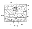
- FIG. 2 shows an embodiment for a mechanical control according to the proposal of the invention.
- the valve 18 for the supply of the additional oil and also the valve 27 for the gas ballast supply into the high vacuum stage 2 can be designed in this way.
- a control principle as explained with reference to FIG. 1 (control device 19, sensors 21, 22), is implemented mechanically with the valve 18, 27 shown in FIG.
- the valve shown in Figure 2 comprises a valve housing 31 which consists of the three parts 32, 33 and 34.
- a membrane 35 is clamped between the housing parts 33 and 34.
- the Membrane 35 separates spaces 36 and 37, which are formed in housing parts 33 and 34, respectively.
- the bore 38 leading to the space 36 is connected to the suction area 4 of the high vacuum pump stage 2 (cf. FIG. 1).
- the bore 39 which is connected to the outlet region of the high vacuum stage 2, that is to say to the line 6 having an intermediate vacuum (FIG. 1), opens into the interior 37.
- the housing part 32 there is a chamber 41 to which the line 15 (FIG. 1) is connected. Oil is supplied to the chamber 41 from the oil pump 11 via the line 15, at a pressure which is approximately 1.5 to 1.8 bar in modern vacuum pumps. A channel 42, through which the line 16 is connected, opens into the chamber 41 and passes through the housing part 33. This leads to high vacuum level 2.
- the mouth 43 of the channel 42 in the chamber 41 is associated with a closure piece 44 which is held in position by the compression spring 45.
- the mouth 43 and the closure piece 44 form the actual closure member of the valve 18, 27.
- the pressure of the spring 45 is small compared to the pressure caused by the oil in the chamber 41.
- a metal tongue can also be provided, which keeps the mouth 43 closed in its rest position.
- the valve 18, 27 can also be designed as a piston valve, as is known per se from DE-AS 117 966.
- the membrane 35 is equipped with a plunger 46. With a section 47, this tappet is guided tightly in the housing part 33, so that the space 36 and the channel 42 are separated from one another in a sufficiently tight manner.
- the tappet section 48 passes through part of the channel 42 and lies against the closure piece 44.
- the membrane 35 assumes the position shown in FIG. H. that the closure piece 44 keeps the mouth 43 closed. If the pressure in the space 37 exceeds the pressure in the space 36 by a certain value, which is dependent on the physical properties of the membrane 35, then the plunger 46 moves in the direction of the chamber 41 and thus the closure piece 44 is lifted off the mouth 43. Oil from the chamber 41 then passes through the channel 42 and the line 16 and reaches the high vacuum stage 2 as an auxiliary oil supply.
- the space 36 above the largest part of the membrane 35 has only a small height which is adapted to a still permissible shape of the membrane 35.
- the membrane 35 or a membrane support designated by 49 rests against the inner wall of the space 36.
Landscapes
- Engineering & Computer Science (AREA)
- Mechanical Engineering (AREA)
- General Engineering & Computer Science (AREA)
- Compressors, Vaccum Pumps And Other Relevant Systems (AREA)
- Reciprocating Pumps (AREA)
Abstract
Description
- Die Erfindung bezieht sich auf ein Verfahren für die Zufuhr von Öl in den Schöpfraum der Hochvakuumstufe einer zwei- oder mehrstufigen, ölgeschmierten Vakuumpumpe. Außerdem bezieht sich die Erfindung auf eine für die Durchführung dieses Verfahrens geeignete Vorrichtung.
- Bei ölgeschmierten Vakuumpumpen ist es bekannt und üblich, zu Beginn eines jeden Kompressionsvorganges eine definierte Menge Öl in den Schöpfraum einzubringen. Das Öl hat mehrere Aufgaben: es dient der Schmierung der einander berührenden Bauteile. Außerdem soll es die Oberflächen der Innenteile benetzt halten, um Korrosionen zu vermeiden. Weiterhin ist der Ölstrom in der Lage, sowohl Verunreinigungen (mechanisch, chemisch) als auch Wärme zu transportieren, d. h. den Schöpfraum zu spülen bzw. die Pumpe zu kühlen. Schließlich besteht eine besondere Aufgabe des Öls darin, die Abdichtung zwischen der Ansaugseite und der Auslaßseite zu verbessern. Die für diese unterschiedlichen Aufgaben benötigten Ölmengen sind unterschiedlich. Die Wahl der in den Schöpfraum vor jedem Kompressionsvorgang einzubringenden Ölmenge beruht deshalb auf einem Kompromiß. Jede der Aufgaben soll das Öl möglichst gut erfüllen, und zwar bei unterschiedlichen Betriebsbedingungen. Es ist bereits bekannt, daß der Ölbedarf einer Vakuumpumpe unter verschiedenen Betriebsbedingungen unterschiedlich ist. Bei hohen Förderleistungen sind in der ersten Stufe größere Ölmengen erforderlich als bei geringen Förderleistungen.
- Aus der DE-AS 11 79 666 ist eine einstufige Drehkolbenpumpe zur Vakuumerzeugung bekannt, die mit einer Steuereinrichtung ausgerüstet ist. Diese steuert eine zusätzliche Ölzufuhr. Sie arbeitet in Abhängigkeit vom Druck im Kompressionsraum des Schöpfraumes, der bei hoher Förderleistung oberhalb des Atmosphärendruckes liegt und bei geringer Förderleistung (Enddruckbetrieb) einen Unterdruck aufweist. Mit Hilfe eines unter der Wirkung dieser verschiedenen Drücke stehenden Kolbens wird die Zusatzöl-Zufuhr derart gesteuert, daß bei hohem Druck im Kompressionsraum viel Zusatzöl in den Schöpfraum eingelassen wird. Eine derartige Steuerung der Ölzufuhr ist für die Hochvakuumstufe einer zwei- oder mehrstufigen Vakuumpumpe nicht einsetzbar, da sie ungenau arbeitet. Der Druck im Kompressionsraum moderner Vakuumpumpen hängt nicht nur von der Förderleistung ab; ein Druckaufbau kann auch bei geringeren Förderleistungen stattfinden, wenn z. B. nachgeordnete Ölfilter mit Schmutz belastet sind. In einem solchen Fall würde also auch im Enddruckbetrieb viel Öl in den Schöpfraum einströmen, was gerade nicht erwünscht ist.
- Der vorliegenden Erfindung liegt die Aufgabe zugrunde, ein Verfahren und eine Vorrichtung der eingangs genannten Art zu schaffen, mit deren Hilfe eine exakte betriebsabhängige Steuerung der Ölversorgung der Hochvakuumstufe einer zwei- oder mehrstufigen Vakuumpumpe möglich ist.
- Erfindungsgemäß wird diese Aufgabe bei einem Verfahren der eingangs genannten Art dadurch gelöst, daß eine ständige Ölzufuhr vorhanden ist, die für den Betrieb der Hochvakuumstufe im Enddruckbereich ausreicht, und daß zusätzliches Öl in den Schöpfraum eingelassen wird, wenn die Differenz der Drücke im Ansaugbereich und im Auslaßbereich der Hochvakuumstufe einen bestimmten Wert überschreitet. Durch diese Maßnahmen kann erreicht werden, daß im Enddruckbereich eine Mangel- oder Sparschmierung aufrechterhalten werden kann. Überschreitet die Druckdifferenz zwischen Ansaugbereich und Auslaßbereich der Hochvakuumstufe einen bestimmten für die jeweilige Pumpe charakteristischen Wert, dann setzt eine zusätzliche Ölzufuhr ein, die zur verbesserten Schmierung, Kühlung, Spülung und Abdichtung der Hochvakuumstufe führt und damit verbesserte Pumpeigenschaften bewirkt.
- Für die Durchführung dieses Betriebsverfahrens ist die Verwendung eines Ventiles zweckmäßig, dem Steuermittel zugeordnet sind, die in Abhängigkeit vom Betriebszustand der Hochvakuumstufe arbeiten. Diese Mittel können elektrisch ausgebildet sein und Sensoren sowie eine elektronische Steuerung umfassen. Bei einer besonders einfachen mechanischen Lösung ist ein Ventil vorgesehen, das mit einer Membran als Steuerelement ausgerüstet ist. Die Räume auf den beiden Seiten der Membran sind mit dem Ansaugbereich bzw. Auslaßbereich der Hochvakuumstufe verbunden. Die Membran kann beispielsweise mit einem Stößel verbunden sein, der einen Ventilmechanismus betätigt. Ventile dieser Art sind kostengünstig. Störende, durch Reibung verursachte Kraftanteile sind klein, so daß insgesamt die saugdruckunabhängigen Krafteinflüsse minimal sind. Eine exakte saugdruckabhängige Steuerung mit sensibler Schaltgrenze ist deshalb möglich. Mit Hilfe der Eigenschaften der Membran (Größe, Flexibilität usw.) lassen sich definierte Steuergrenzen einstellen.
- Ein besonderer Vorteil der Erfindung liegt noch darin, daß wegen der besonderen saugdruckabhängigen Steuerung die Anpassung der Ölzufuhr an die verschiedenen Betriebszustände besonders empfindlich ist. Es ist deshalb ohne Gefahr für die Pumpe möglich, auch in die Hochvakuumstufe Gasballast einzulassen, wenn die Gefahr von Kondensationen des geförderten Gases in der Hochvakuumstufe besteht. Die empfindliche Steuereinrichtung "erkennt" sofort einen derartigen Betrieb und bewirkt eine erhöhte Ölzufuhr, die für den Gasballastbetrieb erforderlich ist.
- Weitere Vorteile und Einzelheiten der Erfindung sollen anhand der Figuren 1 und 2 erläutert werden. Es zeigen
- - Figur 1 ein Schema für eine zweistufige Vakuumpumpe mit der erfindungsgemäßen Steuerung und
- - Figur 2 ein Beispiel für ein Steuerventil.
- Beim Schema einer zweistufigen Vakuumpumpe 1 nach Figur 1 sind die Hochvakuumstufe mit 2 und die Vorvakuumstufe mit 3 bezeichnet. An den Einlaß 4 der Hochvakuumstufe 2 ist während des Betriebs ein zu evakuierender Rezipient angeschlossen. Der Auslaß 5 der Hochvakuumstufe 2 ist über eine Leitung 6 mit dem Einlaß 7 der Vorvakuumstufe 3 verbunden. Der Auslaß der Vorvakuumstufe 3 ist mit 8 bezeichnet.
- Zur Versorgung der Stufen 2, 3 mit Öl ist eine Ölpumpe 11 vorgesehen, die Öl vom Ölsumpf 12 über die Leitungsabschnitte 13 bis 16 zu den Pumpstufen 2 und 3 fördert. Die der Vorvakuumstufe 3 zugeführte Ölmenge ist konstant und bestimmt durch die in der Leitung 14 eingeschaltete Engstelle 17. In die Leitung 15, 16 ist ein Ventil 18 eingeschaltet, das in Abhängigkeit von der allgemein als Block dargestellten Steuereinrichtung 19 arbeitet.
- Der Steuereinrichtung 19 sind Drucksensoren 21, 22 zugeordnet, die den Ansaugdruck (Sensor 21) und den Druck im Auslaßbereich der Hochvakuumstufe (Zwischenvakuum) registrieren und in Form von elektrischen Signalen der Steuereinrichtung 19 über die Leitungen 23, 24 zuführen. Die Differenz dieser beiden Druckwerte wird in der Steuereinrichtung 19 gebildet und mit einem Sollwert verglichen. Bei einer zweistufigen Vakuumpumpe mit einem Stufungsverhältnis von 4 : 1 liegt dieser Sollwert beispielsweise zwischen 10 und 30 mbar. Liegt die gemessene Druckdifferenz über diesem Wert, ist es erforderlich, die Hochvakuumstufe mit Zusatzöl zu versorgen. Dazu wird über die Steuerleitung 25 das Ventil 18 geöffnet. Sobald die gemessene Druckdifferenz den Sollwert unterschreitet, schließt das Ventil 18, so daß die Hochvakuumstufe 2 lediglich mit einer Sparschmierung betrieben wird. Für diesen Betriebszustand kann beispielsweise die Ölmenge ausreichend sein, die über die Lagerungen der Rotorwelle in den Schöpfraum der Hochvakuumstufe 2 gelangt.
- Beim Ausführungsbeispiel nach Figur 1 sind noch Ventile 26, 27 vorgesehen, die dem Einlaß von Gasballast in die Vorvakuumstufe 3 bzw. Hochvakuumstufe 2 dienen. Der Einlaß von Gasballast in die Hochvakuumstufe 2 kann automatisiert werden, und zwar ebenfalls in Abhängigkeit von der Differenz der Drücke im Ansaugbereich und im Auslaßbereich der Hochvakuumstufe 2. Dazu ist das Ventil 27 über die Steuerleitung 28 mit der Steuereinrichtung 19 verbunden. Diese Lösung ist sinnvoll, wenn beispielsweise der Wert für den Differenzdruck, bei dem das Gasballastventil 27 öffnen soll, anwendungsspezifisch festgelegt werden kann. Unabhängig davon, ob die Öffnung des Ventils 27 in dieser Weise automatisch oder auch von Hand erfolgt, wird sich die Versorgung der Hochvakuumstufe 2 mit Zusatzöl über das Ventil 18 automatisch an die Betriebsbedingungen anpassen.
- Figur 2 zeigt ein Ausführungsbeispiel für eine mechanische Steuerung entsprechend dem Vorschlag nach der Erfindung. Das Ventil 18 für die Zufuhr des Zusatzöles und auch das Ventil 27 für die Gasballastzufuhr in die Hochvakuumstufe 2 können in dieser Weise ausgebildet sein. Ein Steuerungsprinzip, wie es anhand der Figur 1 (Steuereinrichtung 19, Sensoren 21, 22) erläutert wurde, ist mit dem in Figur 2 dargestellten Ventil 18, 27 mechanisch verwirklicht.
- Das in Figur 2 dargestellte Ventil umfaßt ein Ventilgehäuse 31, das aus den drei Teilen 32, 33 und 34 besteht. Zwischen den Gehäuseteilen 33 und 34 ist eine Membran 35 eingespannt. Die Membran 35 trennt die Räume 36 und 37 voneinander, welche in den Gehäuseteilen 33 bzw. 34 ausgebildet sind. Die zum Raum 36 führende Bohrung 38 ist mit dem Ansaugbereich 4 der Hochvakuumpumpenstufe 2 (vgl. Figur 1) verbunden. Die Bohrung 39, die mit dem Auslaßbereich der Hochvakuumstufe 2, also mit der Zwischenvakuum aufweisenden Leitung 6 (Figur 1) verbunden ist, mündet in den Innenraum 37.
- Im Gehäuseteil 32 befindet sich eine Kammer 41, an die die Leitung 15 (Figur 1) angeschlossen ist. Über die Leitung 15 wird der Kammer 41 Öl von der Ölpumpe 11 zugeführt, und zwar mit einem Druck, der bei modernen Vakuumpumpen etwa 1,5 bis 1,8 bar beträgt. In die Kammer 41 mündet ein das Gehäuseteil 33 durchsetzender Kanal 42, an den die Leitung 16 angeschlossen ist. Diese führt zur Hochvakuumstufe 2.
- Der Mündung 43 des Kanals 42 in die Kammer 41 ist ein Verschlußstück 44 zugeordnet, das von der Druckfeder 45 in seiner Position gehalten wird. Die Mündung 43 und das Verschlußstück 44 bilden das eigentliche Verschlußorgan des Ventiles 18, 27. Der Druck der Feder 45 ist im Vergleich zum Druck, verursacht durch das in der Kammer 41 befindliche Öl, klein. Anstelle des federbelasteten Verschlußstückes 44 kann auch eine Metallzunge vorgesehen sein, die in ihrer Ruhestellung die Mündung 43 verschlossen hält. Im übrigen kann das Ventil 18, 27 auch als Kolbenventil ausgebildet sein, wie es aus der DE-AS 117 966 an sich vorbekannt ist.
- Die Membran 35 ist mit einem Stößel 46 ausgerüstet. Mit einem Abschnitt 47 ist dieser Stößel dicht im Gehäuseteil 33 geführt, so daß Raum36 und Kanal 42 ausreichend dicht voneinander getrennt sind. Der Stößelabschnitt 48 durchsetzt einen Teil des Kanals 42 und liegt dem Verschlußstück 44 an.
- Sind die Drücke in den Räumen 36, 37 etwa gleich oder nur geringfügig unterschiedlich, dann nimmt die Membrane 35 die in der Figur 2 dargestellte Stellung ein, d. h. daß das Verschlußstück 44 die Mündung 43 geschlossen hält. Übersteigt der Druck im Raum 37 den Druck im Raum 36 um einen bestimmten, von den physikalischen Eigenschaften der Membran 35 abhängigen Wert, dann ergibt sich eine Bewegung des Stößels 46 in Richtung der Kammer 41 und damit ein Abheben des Verschlußstückes 44 von der Mündung 43. Öl aus der Kammer 41 tritt dann durch den Kanal 42 und die Leitung 16 hindurch und gelangt als Zusatzölversorgung in die Hochvakuumstufe 2.
- Zum Schutz der Membran 35 gegen zu hohe Drücke weist der Raum 36 oberhalb des größten Teiles der Membran 35 nur eine geringe, einer noch zulässigen Ausformung der Membran 35 angepaßte Höhe auf. Im Falle eines überhöhten Druckes im Raum 37 legt sich die Membran 35 oder ein mit 49 bezeichneter Membranträger an die Innenwand des Raumes 36 an.
Claims (10)
Priority Applications (3)
| Application Number | Priority Date | Filing Date | Title |
|---|---|---|---|
| EP89110196A EP0401399B1 (de) | 1989-06-06 | 1989-06-06 | Zwei- oder mehrstufige Hochvakuumpumpe |
| DE89110196T DE58907121D1 (de) | 1989-06-06 | 1989-06-06 | Zwei- oder mehrstufige Hochvakuumpumpe. |
| US07/533,535 US5066202A (en) | 1989-06-06 | 1990-06-05 | Method and apparatus for delivering oil to a multi-stage pump |
Applications Claiming Priority (1)
| Application Number | Priority Date | Filing Date | Title |
|---|---|---|---|
| EP89110196A EP0401399B1 (de) | 1989-06-06 | 1989-06-06 | Zwei- oder mehrstufige Hochvakuumpumpe |
Publications (2)
| Publication Number | Publication Date |
|---|---|
| EP0401399A1 true EP0401399A1 (de) | 1990-12-12 |
| EP0401399B1 EP0401399B1 (de) | 1994-03-02 |
Family
ID=8201466
Family Applications (1)
| Application Number | Title | Priority Date | Filing Date |
|---|---|---|---|
| EP89110196A Expired - Lifetime EP0401399B1 (de) | 1989-06-06 | 1989-06-06 | Zwei- oder mehrstufige Hochvakuumpumpe |
Country Status (3)
| Country | Link |
|---|---|
| US (1) | US5066202A (de) |
| EP (1) | EP0401399B1 (de) |
| DE (1) | DE58907121D1 (de) |
Cited By (3)
| Publication number | Priority date | Publication date | Assignee | Title |
|---|---|---|---|---|
| DE4325283A1 (de) * | 1993-07-28 | 1995-02-02 | Leybold Ag | Betriebsabhängig steuerbares Ventilsystem für eine Vakuumpumpe |
| WO1995005540A1 (de) * | 1993-08-17 | 1995-02-23 | Leybold Aktiengesellschaft | Vakuumpumpe mit ölabscheider |
| IT201800021148A1 (it) * | 2018-12-27 | 2020-06-27 | D V P Vacuum Tech S P A | Pompa ausiliaria volumetrica per la generazione del vuoto. |
Families Citing this family (9)
| Publication number | Priority date | Publication date | Assignee | Title |
|---|---|---|---|---|
| JP2530765B2 (ja) * | 1990-08-31 | 1996-09-04 | 株式会社神戸製鋼所 | 油冷式圧縮機の運転方法 |
| GB9223804D0 (en) * | 1992-11-13 | 1993-01-06 | Boc Group Plc | Improvements in vacuum pumps |
| DE4325281A1 (de) * | 1993-07-28 | 1995-02-02 | Leybold Ag | Vakuumpumpe mit einer Gasballasteinrichtung |
| DE19962445A1 (de) * | 1999-12-22 | 2001-06-28 | Leybold Vakuum Gmbh | Trockenverdichtende Vakuumpumpe mit Gasballasteinrichtung |
| US6695591B2 (en) * | 2002-05-20 | 2004-02-24 | Grimmer Industries, Inc. | Multi-stage gas compressor system |
| DE10255792C5 (de) * | 2002-11-28 | 2008-12-18 | Vacuubrand Gmbh + Co Kg | Verfahren zur Steuerung einer Vakuumpumpe sowie Vakuumpumpensystem |
| GB0413776D0 (en) * | 2004-06-18 | 2004-07-21 | Boc Group Plc | Vacuum pump |
| DK2296962T3 (da) * | 2008-03-10 | 2012-03-05 | Burckhardt Compression Ag | Indretning og fremgangsmåde til behandling af naturgas (LNG) |
| DE102013203268A1 (de) * | 2013-02-27 | 2014-08-28 | Bitzer Kühlmaschinenbau Gmbh | Kältemittelverdichteranlage |
Citations (6)
| Publication number | Priority date | Publication date | Assignee | Title |
|---|---|---|---|---|
| US2779533A (en) * | 1953-12-22 | 1957-01-29 | Leybolds Nachfolger E | High-vacuum rotary oil pumps |
| DE2028603A1 (de) * | 1969-06-12 | 1970-12-23 | ||
| US4063855A (en) * | 1976-05-03 | 1977-12-20 | Fuller Company | Compressor capacity and lubrication control system |
| DE2854741A1 (de) * | 1978-12-19 | 1980-06-26 | Dienes Werke | Entlastungsventil fuer verdichter |
| DE3315748A1 (de) * | 1983-04-30 | 1984-10-31 | Westfalia Separator Ag, 4740 Oelde | Oeldosiervorrichtung fuer vakuumpumpen von melkanlagen |
| DE3706583A1 (de) * | 1987-02-25 | 1988-09-08 | Mannesmann Ag | Verteilung der schmier- und kuehlfluessigkeit in schraubenverdichtern |
Family Cites Families (4)
| Publication number | Priority date | Publication date | Assignee | Title |
|---|---|---|---|---|
| DE228603C (de) * | ||||
| US3395856A (en) * | 1966-12-30 | 1968-08-06 | Caterpillar Tractor Co | Air compressor oil control system |
| US4383802A (en) * | 1981-07-06 | 1983-05-17 | Dunham-Bush, Inc. | Oil equalization system for parallel connected compressors |
| US4605357A (en) * | 1984-06-18 | 1986-08-12 | Ingersoll-Rand Company | Lubrication system for a compressor |
-
1989
- 1989-06-06 DE DE89110196T patent/DE58907121D1/de not_active Expired - Fee Related
- 1989-06-06 EP EP89110196A patent/EP0401399B1/de not_active Expired - Lifetime
-
1990
- 1990-06-05 US US07/533,535 patent/US5066202A/en not_active Expired - Fee Related
Patent Citations (6)
| Publication number | Priority date | Publication date | Assignee | Title |
|---|---|---|---|---|
| US2779533A (en) * | 1953-12-22 | 1957-01-29 | Leybolds Nachfolger E | High-vacuum rotary oil pumps |
| DE2028603A1 (de) * | 1969-06-12 | 1970-12-23 | ||
| US4063855A (en) * | 1976-05-03 | 1977-12-20 | Fuller Company | Compressor capacity and lubrication control system |
| DE2854741A1 (de) * | 1978-12-19 | 1980-06-26 | Dienes Werke | Entlastungsventil fuer verdichter |
| DE3315748A1 (de) * | 1983-04-30 | 1984-10-31 | Westfalia Separator Ag, 4740 Oelde | Oeldosiervorrichtung fuer vakuumpumpen von melkanlagen |
| DE3706583A1 (de) * | 1987-02-25 | 1988-09-08 | Mannesmann Ag | Verteilung der schmier- und kuehlfluessigkeit in schraubenverdichtern |
Cited By (4)
| Publication number | Priority date | Publication date | Assignee | Title |
|---|---|---|---|---|
| DE4325283A1 (de) * | 1993-07-28 | 1995-02-02 | Leybold Ag | Betriebsabhängig steuerbares Ventilsystem für eine Vakuumpumpe |
| WO1995005540A1 (de) * | 1993-08-17 | 1995-02-23 | Leybold Aktiengesellschaft | Vakuumpumpe mit ölabscheider |
| IT201800021148A1 (it) * | 2018-12-27 | 2020-06-27 | D V P Vacuum Tech S P A | Pompa ausiliaria volumetrica per la generazione del vuoto. |
| EP3674555A1 (de) * | 2018-12-27 | 2020-07-01 | D.V.P. Vacuum Technology S.p.A. | Volumetrische hilfspumpe zur erzeugung von vakuum |
Also Published As
| Publication number | Publication date |
|---|---|
| EP0401399B1 (de) | 1994-03-02 |
| US5066202A (en) | 1991-11-19 |
| DE58907121D1 (de) | 1994-04-07 |
Similar Documents
| Publication | Publication Date | Title |
|---|---|---|
| EP0401399B1 (de) | Zwei- oder mehrstufige Hochvakuumpumpe | |
| EP0752531B2 (de) | Vorrichtung zum raschen Evakuieren einer Vakuumkammer | |
| DE3815094C2 (de) | ||
| DE3133502C2 (de) | ||
| DE19821686A1 (de) | Rückschlagventileinheit | |
| EP1299649B1 (de) | Vakuumerzeugervorrichtung | |
| DE1628144B2 (de) | Saugdrosselsteuereinrichtung | |
| DE1403453A1 (de) | Verbesserungen an Kompressor-Aggregaten | |
| DE102013108090A1 (de) | Pumpenanordnung | |
| DE102006000099B4 (de) | Membranpumpe | |
| DE10061384B4 (de) | Strahlpumpenanordnung zur Erzeugung von Vakuum sowie Verfahren zum Betreiben einer solchen Strahlpumpenanordnung | |
| EP0084085A1 (de) | Vakuumpumpe mit einem Saugstutzen-Ventil und Betriebsverfahren dafür | |
| EP0972938B1 (de) | Gasballasteinrichtung für eine mehrstufige Verdrängerpumpe | |
| DE1501146A1 (de) | Einrichtung zum Entfernen nicht kondensierbarer Gase aus Kuehlmittelkreislaeufen | |
| DE69400792T2 (de) | Vorrichtung zur erzeugung einer inerten atmosphäre innerhalb eines lagertanks | |
| DE3320017C2 (de) | Kältemittelkreislauf | |
| EP0541989B1 (de) | Mehrstufiges Vakuum-Pumpsystem | |
| DE3040905A1 (de) | Unterdruck-steuerventil fuer eine abgasreinigungsanlage | |
| WO2001083990A1 (de) | Vorrichtung zum fördern feuchter gase | |
| DE2940235C2 (de) | Einrichtung zum selbsttätigen Ergänzen des Schmieröls in der Kurbelwanne einer Brennkraftmaschine | |
| DE60032095T2 (de) | Automatischer Regler zum Saugen von Luft in einen Behälter | |
| DE3234182A1 (de) | Vorrichtung zur hydraulischen hilfskrafterzeugung | |
| DE2951305A1 (de) | Drucklufterzeugungsanlage | |
| EP0129004B1 (de) | Verdichteranlage | |
| EP0093191A1 (de) | Druckregler |
Legal Events
| Date | Code | Title | Description |
|---|---|---|---|
| PUAI | Public reference made under article 153(3) epc to a published international application that has entered the european phase |
Free format text: ORIGINAL CODE: 0009012 |
|
| AK | Designated contracting states |
Kind code of ref document: A1 Designated state(s): DE GB |
|
| 17P | Request for examination filed |
Effective date: 19910502 |
|
| 17Q | First examination report despatched |
Effective date: 19920428 |
|
| GRAA | (expected) grant |
Free format text: ORIGINAL CODE: 0009210 |
|
| AK | Designated contracting states |
Kind code of ref document: B1 Designated state(s): DE GB |
|
| GBT | Gb: translation of ep patent filed (gb section 77(6)(a)/1977) |
Effective date: 19940224 |
|
| REF | Corresponds to: |
Ref document number: 58907121 Country of ref document: DE Date of ref document: 19940407 |
|
| PLBE | No opposition filed within time limit |
Free format text: ORIGINAL CODE: 0009261 |
|
| STAA | Information on the status of an ep patent application or granted ep patent |
Free format text: STATUS: NO OPPOSITION FILED WITHIN TIME LIMIT |
|
| 26N | No opposition filed | ||
| PGFP | Annual fee paid to national office [announced via postgrant information from national office to epo] |
Ref country code: GB Payment date: 19970520 Year of fee payment: 9 |
|
| PGFP | Annual fee paid to national office [announced via postgrant information from national office to epo] |
Ref country code: DE Payment date: 19970523 Year of fee payment: 9 |
|
| PG25 | Lapsed in a contracting state [announced via postgrant information from national office to epo] |
Ref country code: GB Free format text: LAPSE BECAUSE OF NON-PAYMENT OF DUE FEES Effective date: 19980606 |
|
| GBPC | Gb: european patent ceased through non-payment of renewal fee |
Effective date: 19980606 |
|
| PG25 | Lapsed in a contracting state [announced via postgrant information from national office to epo] |
Ref country code: DE Free format text: LAPSE BECAUSE OF NON-PAYMENT OF DUE FEES Effective date: 19990401 |