EP3674555A1 - Volumetrische hilfspumpe zur erzeugung von vakuum - Google Patents
Volumetrische hilfspumpe zur erzeugung von vakuum Download PDFInfo
- Publication number
- EP3674555A1 EP3674555A1 EP19216999.3A EP19216999A EP3674555A1 EP 3674555 A1 EP3674555 A1 EP 3674555A1 EP 19216999 A EP19216999 A EP 19216999A EP 3674555 A1 EP3674555 A1 EP 3674555A1
- Authority
- EP
- European Patent Office
- Prior art keywords
- pressure
- control unit
- value
- discharge duct
- auxiliary pump
- Prior art date
- Legal status (The legal status is an assumption and is not a legal conclusion. Google has not performed a legal analysis and makes no representation as to the accuracy of the status listed.)
- Granted
Links
Images
Classifications
-
- F—MECHANICAL ENGINEERING; LIGHTING; HEATING; WEAPONS; BLASTING
- F04—POSITIVE - DISPLACEMENT MACHINES FOR LIQUIDS; PUMPS FOR LIQUIDS OR ELASTIC FLUIDS
- F04C—ROTARY-PISTON, OR OSCILLATING-PISTON, POSITIVE-DISPLACEMENT MACHINES FOR LIQUIDS; ROTARY-PISTON, OR OSCILLATING-PISTON, POSITIVE-DISPLACEMENT PUMPS
- F04C18/00—Rotary-piston pumps specially adapted for elastic fluids
- F04C18/08—Rotary-piston pumps specially adapted for elastic fluids of intermeshing-engagement type, i.e. with engagement of co-operating members similar to that of toothed gearing
- F04C18/12—Rotary-piston pumps specially adapted for elastic fluids of intermeshing-engagement type, i.e. with engagement of co-operating members similar to that of toothed gearing of other than internal-axis type
- F04C18/126—Rotary-piston pumps specially adapted for elastic fluids of intermeshing-engagement type, i.e. with engagement of co-operating members similar to that of toothed gearing of other than internal-axis type with radially from the rotor body extending elements, not necessarily co-operating with corresponding recesses in the other rotor, e.g. lobes, Roots type
-
- F—MECHANICAL ENGINEERING; LIGHTING; HEATING; WEAPONS; BLASTING
- F04—POSITIVE - DISPLACEMENT MACHINES FOR LIQUIDS; PUMPS FOR LIQUIDS OR ELASTIC FLUIDS
- F04C—ROTARY-PISTON, OR OSCILLATING-PISTON, POSITIVE-DISPLACEMENT MACHINES FOR LIQUIDS; ROTARY-PISTON, OR OSCILLATING-PISTON, POSITIVE-DISPLACEMENT PUMPS
- F04C25/00—Adaptations of pumps for special use of pumps for elastic fluids
- F04C25/02—Adaptations of pumps for special use of pumps for elastic fluids for producing high vacuum
-
- F—MECHANICAL ENGINEERING; LIGHTING; HEATING; WEAPONS; BLASTING
- F04—POSITIVE - DISPLACEMENT MACHINES FOR LIQUIDS; PUMPS FOR LIQUIDS OR ELASTIC FLUIDS
- F04C—ROTARY-PISTON, OR OSCILLATING-PISTON, POSITIVE-DISPLACEMENT MACHINES FOR LIQUIDS; ROTARY-PISTON, OR OSCILLATING-PISTON, POSITIVE-DISPLACEMENT PUMPS
- F04C28/00—Control of, monitoring of, or safety arrangements for, pumps or pumping installations specially adapted for elastic fluids
- F04C28/06—Control of, monitoring of, or safety arrangements for, pumps or pumping installations specially adapted for elastic fluids specially adapted for stopping, starting, idling or no-load operation
-
- F—MECHANICAL ENGINEERING; LIGHTING; HEATING; WEAPONS; BLASTING
- F04—POSITIVE - DISPLACEMENT MACHINES FOR LIQUIDS; PUMPS FOR LIQUIDS OR ELASTIC FLUIDS
- F04C—ROTARY-PISTON, OR OSCILLATING-PISTON, POSITIVE-DISPLACEMENT MACHINES FOR LIQUIDS; ROTARY-PISTON, OR OSCILLATING-PISTON, POSITIVE-DISPLACEMENT PUMPS
- F04C28/00—Control of, monitoring of, or safety arrangements for, pumps or pumping installations specially adapted for elastic fluids
- F04C28/08—Control of, monitoring of, or safety arrangements for, pumps or pumping installations specially adapted for elastic fluids characterised by varying the rotational speed
-
- F—MECHANICAL ENGINEERING; LIGHTING; HEATING; WEAPONS; BLASTING
- F04—POSITIVE - DISPLACEMENT MACHINES FOR LIQUIDS; PUMPS FOR LIQUIDS OR ELASTIC FLUIDS
- F04C—ROTARY-PISTON, OR OSCILLATING-PISTON, POSITIVE-DISPLACEMENT MACHINES FOR LIQUIDS; ROTARY-PISTON, OR OSCILLATING-PISTON, POSITIVE-DISPLACEMENT PUMPS
- F04C2270/00—Control; Monitoring or safety arrangements
- F04C2270/05—Speed
-
- F—MECHANICAL ENGINEERING; LIGHTING; HEATING; WEAPONS; BLASTING
- F04—POSITIVE - DISPLACEMENT MACHINES FOR LIQUIDS; PUMPS FOR LIQUIDS OR ELASTIC FLUIDS
- F04C—ROTARY-PISTON, OR OSCILLATING-PISTON, POSITIVE-DISPLACEMENT MACHINES FOR LIQUIDS; ROTARY-PISTON, OR OSCILLATING-PISTON, POSITIVE-DISPLACEMENT PUMPS
- F04C2270/00—Control; Monitoring or safety arrangements
- F04C2270/07—Electric current
-
- F—MECHANICAL ENGINEERING; LIGHTING; HEATING; WEAPONS; BLASTING
- F04—POSITIVE - DISPLACEMENT MACHINES FOR LIQUIDS; PUMPS FOR LIQUIDS OR ELASTIC FLUIDS
- F04C—ROTARY-PISTON, OR OSCILLATING-PISTON, POSITIVE-DISPLACEMENT MACHINES FOR LIQUIDS; ROTARY-PISTON, OR OSCILLATING-PISTON, POSITIVE-DISPLACEMENT PUMPS
- F04C2270/00—Control; Monitoring or safety arrangements
- F04C2270/18—Pressure
Definitions
- This invention relates to an auxiliary volumetric pump for generating a vacuum.
- volumetric auxiliary pump means a "booster" pump, generally called a “roots” pump or a rotary lobes pump, positioned upstream of a primary pump, for example of the rotary blade type, for generating a vacuum in systems in which it is necessary to manage high fluid flow rates and to speed up the emptying time of the system.
- an auxiliary pump for generating a vacuum comprising a casing, a rotary member housed in the casing and an electric motor for powering the rotary member.
- the auxiliary pump comprises an intake duct, located downstream of a user device, and a discharge duct configured to define a delivery duct of a primary pump.
- a device for detecting the pressure of the fluid entering the auxiliary pump designed for emitting a signal for detecting the pressure of the fluid entering the auxiliary pump, is positioned in the intake duct.
- a device for detecting the pressure of the fluid leaving the auxiliary pump designed for emitting a signal for detecting the pressure of the fluid leaving the auxiliary pump, is positioned in the discharge duct.
- a control unit is configured to receive and process the signal for detecting the pressure of the fluid entering and flowing out from the auxiliary pump and determining the pressure of the fluid in the intake duct and in the discharge duct and the pressure difference between the pressure value in the intake duct and in the discharge duct.
- the control unit is configured for controlling the frequency of rotation and the absorption of the electric motor by the rotary member as a function of the pressure difference between the pressure value in the intake duct and in the discharge duct, if less than a pre-set permissible pressure difference.
- this operating mode protects the electric motor of the auxiliary pump against malfunctions or faults since the current absorption is determined by the pressure difference between the pressure value in the intake duct and in the discharge duct, below the threshold value declared by the manufacturer of the auxiliary pump.
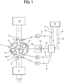
- Thenumeral 1 denotes an auxiliary volumetric pump for generating the vacuum according to the invention.
- the auxiliary pump 1 comprises an intake duct 2 and a discharge duct 3.
- the intake duct 2 is located downstream of a user device 24, with reference to the direction of flow of the fluid.
- the discharge duct 3 is configured to define a delivery duct of a primary pump 4.
- the primary pump 4 is positioned downstream of the auxiliary pump 1, with reference to the direction of flow of the fluid.
- a device for detecting the pressure 5 of the fluid entering the auxiliary pump 1 designed for emitting a signal for detecting the pressure 8 of the fluid entering the auxiliary pump 1, is positioned in the intake duct 2.
- a device for detecting the pressure 6 of the fluid flowing out from the auxiliary pump 1, designed for emitting a signal for detecting the pressure 9 of the fluid flowing out of the auxiliary pump 1, is positioned in the discharge duct 3.
- a control unit 7 is configured for receiving and processing the signal for measuring the pressure 8 of the fluid entering the auxiliary pump 1 and determining the pressure of the fluid in the intake duct 2.
- the control unit 7 is configured for receiving and processing the signal for measuring the pressure 9 of the fluid flowing out from the auxiliary pump 1 and determining the pressure of the fluid in the discharge duct 3.
- the control unit 7 is configured to receive and process the signals for detecting the pressure 8, 9 of the fluid entering and flowing out and determining the pressure difference between the pressure value in the intake duct 2 and in the discharge duct 3.
- the control unit 7 is configured for controlling the frequency of rotation and the absorption of the electric motor 21 by the rotary member 11 as a function of the pressure difference between the pressure value in the intake duct and in the discharge duct, if less than a pre-set permissible pressure difference.
- the control unit 7 is configured for comparing the value of the pressure of the fluid in the discharge duct 3 with a threshold pressure value.
- control unit 7 determines that the value of the pressure in the discharge duct 3 is greater than the threshold pressure value for a set period of time, the control unit 7 is configured to emit a first alarm signal 16.
- This malfunction condition that is to say, a pressure in the discharge duct 3 between the auxiliary pump 1 and the primary pump 4, may occur, for example, if the primary pump 4 is subject to a malfunction, the primary pump 4 switched off.
- the control unit 7 is configured for comparing the value of the pressure of the fluid in the discharge duct 3 with a control pressure value.
- control unit 7 determines that the pressure value in the discharge duct 3 is less than the control pressure value, the control unit 7 does not take any action.
- control unit 7 determines that the pressure value in the discharge duct 3 is greater than the control pressure value, the control unit 7 is configured for storing the value of the pressure determined by means of the signal for measuring the pressure 9 of the fluid flowing out from the auxiliary pump 1.
- the control unit 7 is configured for continuously measuring the pressure values determined by means of the respective signals for measuring the pressure 9 of the fluid flowing out from the auxiliary pump 1.
- the control unit 7 is configured to determine whether or not the new pressure values are within a range of pressure values defined by the pressure value stored in a respective time interval.
- control unit 7 determines that the pressure values are within said range of pressure values, according to a respective time interval, the control unit 7 is configured to send a second alarm signal 17.
- control unit 7 determines that the new pressure value is not within the range of pressure values, the control unit 7 is configured for storing the new pressure value and, after a predetermined period of time, the control unit 7 is configured for measuring a new pressure value determined by the detection signal of the pressure 9 of the fluid flowing out from the auxiliary pump 1 and determining again if the new pressure value is within said range of pressure values defined by the value of the last pressure value stored.
- the auxiliary pump 1 comprises a device for measuring the frequency 20 of the electric motor and is configured for emitting a signal for measuring the frequency 22 of the electric motor 21.
- control unit 7 determines that the value of the frequency of the electric motor 21 is less than the pre-set minimum frequency value for a pre-set period of time, the control unit 7 is configured to emit a third alarm signal 18.
- the minimum frequency set is the frequency necessary to guarantee the circulation of lubricating liquid in the auxiliary pump 1.
- This malfunction condition that is to say, a minimum frequency which continues over time, may occur, for example, when the ratio of the flow rate between auxiliary pump 1 and primary pump 4 is too high, over-absorbing, the primary pump 4 switched off.
- the auxiliary pump 1 comprises a casing 10 and a rotary member 11 housed in the casing 10.
- An electric motor 21 powers the rotary member 11.
- the rotary member 11 comprises at least a first lobe 12, rotating about its own axis 12a of rotation, and a second lobe 13, rotating about its own axis 13a of rotation.
- the first lobe 12 and the second lobe 13 rotate in a synchronous fashion about the respective axes of rotation 12a, 13a for conveying the fluid from the intake duct 2 to the discharge duct 3.
- a device 14 for measuring the temperature is positioned on the casing 10. More specifically, the device 14 for measuring the temperature is positioned on the casing 10 in a zone close to the discharge duct 3.
- the temperature measuring device 14 is configured to measure the temperature of the casing 10 and to emit a warning signal 15 indicating that the temperature has been exceeded a maximum permitted temperature value.
- the temperature measuring device 14 comprises an electrical circuit equipped with a switch whose opening or closing is determined by the temperature of the casing 10 exceeding a maximum permitted temperature value.
- the control unit 7 is configured to receive the warning signal 15 of the temperature measuring device 14 and, upon receiving it, to emit a fourth alarm signal 19.
- This condition of malfunction may occur, for example, if the ambient temperature in which the auxiliary pump 1 is positioned is high, the level or viscosity of the oil is high, the clearances of the rotary member 11 are too high, the suction filter of the auxiliary pump 1 is dirty or due to overloading of the auxiliary pump 1.
- a display device 23 is configured to receive the first, second, third and fourth alarm signals 16, 17, 18, 19 emitted by the control unit 7 and make it visible to an operator.
- the display device 23 makes available the alarm signals by means of a warning light.
- control unit 7 is configured for controlling the switching off of the auxiliary pump 1, that is to say, for controlling the interruption of the electric motor 21 for powering the rotary member 11 upon the emission of at least one of the above-mentioned alarm signals 16, 17, 18, 19.
Landscapes
- Engineering & Computer Science (AREA)
- Mechanical Engineering (AREA)
- General Engineering & Computer Science (AREA)
- Control Of Positive-Displacement Pumps (AREA)
- Rotary Pumps (AREA)
- Compressor (AREA)
Applications Claiming Priority (1)
| Application Number | Priority Date | Filing Date | Title |
|---|---|---|---|
| IT102018000021148A IT201800021148A1 (it) | 2018-12-27 | 2018-12-27 | Pompa ausiliaria volumetrica per la generazione del vuoto. |
Publications (2)
| Publication Number | Publication Date |
|---|---|
| EP3674555A1 true EP3674555A1 (de) | 2020-07-01 |
| EP3674555B1 EP3674555B1 (de) | 2021-05-26 |
Family
ID=66049570
Family Applications (1)
| Application Number | Title | Priority Date | Filing Date |
|---|---|---|---|
| EP19216999.3A Active EP3674555B1 (de) | 2018-12-27 | 2019-12-17 | Volumetrische hilfspumpe zur erzeugung von vakuum |
Country Status (2)
| Country | Link |
|---|---|
| EP (1) | EP3674555B1 (de) |
| IT (1) | IT201800021148A1 (de) |
Citations (4)
| Publication number | Priority date | Publication date | Assignee | Title |
|---|---|---|---|---|
| EP0401399A1 (de) * | 1989-06-06 | 1990-12-12 | Leybold Aktiengesellschaft | Zwei- oder mehrstufige Hochvakuumpumpe |
| JP2007100562A (ja) * | 2005-10-03 | 2007-04-19 | Shinko Seiki Co Ltd | 真空装置 |
| US20170298935A1 (en) * | 2014-09-26 | 2017-10-19 | Ateliers Busch Sa | Vacuum-generating pumping system and pumping method using this pumping system |
| WO2018010970A1 (fr) * | 2016-07-13 | 2018-01-18 | Pfeiffer Vacuum | Procédé de descente en pression dans un sas de chargement et de déchargement et groupe de pompage associé |
-
2018
- 2018-12-27 IT IT102018000021148A patent/IT201800021148A1/it unknown
-
2019
- 2019-12-17 EP EP19216999.3A patent/EP3674555B1/de active Active
Patent Citations (4)
| Publication number | Priority date | Publication date | Assignee | Title |
|---|---|---|---|---|
| EP0401399A1 (de) * | 1989-06-06 | 1990-12-12 | Leybold Aktiengesellschaft | Zwei- oder mehrstufige Hochvakuumpumpe |
| JP2007100562A (ja) * | 2005-10-03 | 2007-04-19 | Shinko Seiki Co Ltd | 真空装置 |
| US20170298935A1 (en) * | 2014-09-26 | 2017-10-19 | Ateliers Busch Sa | Vacuum-generating pumping system and pumping method using this pumping system |
| WO2018010970A1 (fr) * | 2016-07-13 | 2018-01-18 | Pfeiffer Vacuum | Procédé de descente en pression dans un sas de chargement et de déchargement et groupe de pompage associé |
Also Published As
| Publication number | Publication date |
|---|---|
| EP3674555B1 (de) | 2021-05-26 |
| IT201800021148A1 (it) | 2020-06-27 |
Similar Documents
| Publication | Publication Date | Title |
|---|---|---|
| US20210396238A1 (en) | Pump apparatus, test operation method of pump apparatus, motor assembly and method for identifying abnormal vibration of motor assembly | |
| JP5687696B2 (ja) | 体外循環路に血液を送り出すための装置 | |
| US20180306682A1 (en) | Smart pump for a portable gas detection instrument | |
| US20230243357A1 (en) | Bilge pump systems | |
| JP7005766B2 (ja) | 圧縮機及び監視システム | |
| CN111828362A (zh) | 真空泵系统 | |
| EP3674555B1 (de) | Volumetrische hilfspumpe zur erzeugung von vakuum | |
| JP2019120146A (ja) | 電動機組立体、ポンプ装置、および、電動機組立体の異常振動を特定する方法 | |
| US12085085B2 (en) | Vacuum pump system and control method | |
| EP3604808B1 (de) | Gasverdichter mit flüssigkeitszufuhr | |
| JP3570884B2 (ja) | 自動給水装置 | |
| JP2012149668A (ja) | 潤滑油供給排出装置 | |
| US11060902B2 (en) | Abnormality treatment apparatus for rotating machine, and rotating machine system | |
| WO2018128004A1 (ja) | ポンプ装置及びポンプ装置の制御方法 | |
| TW202014605A (zh) | 給液式氣體壓縮機及氣液分離器 | |
| JP7376781B2 (ja) | 油圧ユニット | |
| JP7002965B2 (ja) | 定圧液供給装置 | |
| KR102763709B1 (ko) | 유체압 유닛 | |
| KR100901144B1 (ko) | 송풍팬장치 | |
| WO2025021786A1 (en) | Claw pump | |
| CN108026928A (zh) | 用于双螺杆正排量泵保护的方法 | |
| CN119244508A (zh) | 检测方法、检测装置、空压机及存储介质 | |
| KR940009541B1 (ko) | 디젤엔진의 운전감시 장치 및 그 제어방법 | |
| JP2019173579A (ja) | ポンプシステム、プラント | |
| JPH03279696A (ja) | 電動送風機の異常検出装置 |
Legal Events
| Date | Code | Title | Description |
|---|---|---|---|
| PUAI | Public reference made under article 153(3) epc to a published international application that has entered the european phase |
Free format text: ORIGINAL CODE: 0009012 |
|
| STAA | Information on the status of an ep patent application or granted ep patent |
Free format text: STATUS: THE APPLICATION HAS BEEN PUBLISHED |
|
| AK | Designated contracting states |
Kind code of ref document: A1 Designated state(s): AL AT BE BG CH CY CZ DE DK EE ES FI FR GB GR HR HU IE IS IT LI LT LU LV MC MK MT NL NO PL PT RO RS SE SI SK SM TR |
|
| AX | Request for extension of the european patent |
Extension state: BA ME |
|
| STAA | Information on the status of an ep patent application or granted ep patent |
Free format text: STATUS: REQUEST FOR EXAMINATION WAS MADE |
|
| 17P | Request for examination filed |
Effective date: 20201019 |
|
| RBV | Designated contracting states (corrected) |
Designated state(s): AL AT BE BG CH CY CZ DE DK EE ES FI FR GB GR HR HU IE IS IT LI LT LU LV MC MK MT NL NO PL PT RO RS SE SI SK SM TR |
|
| RIC1 | Information provided on ipc code assigned before grant |
Ipc: F04C 25/02 20060101ALI20201127BHEP Ipc: F04C 18/12 20060101ALI20201127BHEP Ipc: F04C 28/08 20060101ALI20201127BHEP Ipc: F04C 28/06 20060101AFI20201127BHEP |
|
| GRAP | Despatch of communication of intention to grant a patent |
Free format text: ORIGINAL CODE: EPIDOSNIGR1 |
|
| STAA | Information on the status of an ep patent application or granted ep patent |
Free format text: STATUS: GRANT OF PATENT IS INTENDED |
|
| INTG | Intention to grant announced |
Effective date: 20210113 |
|
| GRAS | Grant fee paid |
Free format text: ORIGINAL CODE: EPIDOSNIGR3 |
|
| GRAA | (expected) grant |
Free format text: ORIGINAL CODE: 0009210 |
|
| STAA | Information on the status of an ep patent application or granted ep patent |
Free format text: STATUS: THE PATENT HAS BEEN GRANTED |
|
| AK | Designated contracting states |
Kind code of ref document: B1 Designated state(s): AL AT BE BG CH CY CZ DE DK EE ES FI FR GB GR HR HU IE IS IT LI LT LU LV MC MK MT NL NO PL PT RO RS SE SI SK SM TR |
|
| REG | Reference to a national code |
Ref country code: GB Ref legal event code: FG4D |
|
| REG | Reference to a national code |
Ref country code: CH Ref legal event code: EP |
|
| REG | Reference to a national code |
Ref country code: DE Ref legal event code: R096 Ref document number: 602019004913 Country of ref document: DE |
|
| REG | Reference to a national code |
Ref country code: AT Ref legal event code: REF Ref document number: 1396489 Country of ref document: AT Kind code of ref document: T Effective date: 20210615 |
|
| REG | Reference to a national code |
Ref country code: IE Ref legal event code: FG4D |
|
| REG | Reference to a national code |
Ref country code: LT Ref legal event code: MG9D |
|
| REG | Reference to a national code |
Ref country code: AT Ref legal event code: MK05 Ref document number: 1396489 Country of ref document: AT Kind code of ref document: T Effective date: 20210526 |
|
| PG25 | Lapsed in a contracting state [announced via postgrant information from national office to epo] |
Ref country code: LT Free format text: LAPSE BECAUSE OF FAILURE TO SUBMIT A TRANSLATION OF THE DESCRIPTION OR TO PAY THE FEE WITHIN THE PRESCRIBED TIME-LIMIT Effective date: 20210526 Ref country code: HR Free format text: LAPSE BECAUSE OF FAILURE TO SUBMIT A TRANSLATION OF THE DESCRIPTION OR TO PAY THE FEE WITHIN THE PRESCRIBED TIME-LIMIT Effective date: 20210526 Ref country code: FI Free format text: LAPSE BECAUSE OF FAILURE TO SUBMIT A TRANSLATION OF THE DESCRIPTION OR TO PAY THE FEE WITHIN THE PRESCRIBED TIME-LIMIT Effective date: 20210526 Ref country code: BG Free format text: LAPSE BECAUSE OF FAILURE TO SUBMIT A TRANSLATION OF THE DESCRIPTION OR TO PAY THE FEE WITHIN THE PRESCRIBED TIME-LIMIT Effective date: 20210826 Ref country code: AT Free format text: LAPSE BECAUSE OF FAILURE TO SUBMIT A TRANSLATION OF THE DESCRIPTION OR TO PAY THE FEE WITHIN THE PRESCRIBED TIME-LIMIT Effective date: 20210526 |
|
| REG | Reference to a national code |
Ref country code: NL Ref legal event code: MP Effective date: 20210526 |
|
| PG25 | Lapsed in a contracting state [announced via postgrant information from national office to epo] |
Ref country code: GR Free format text: LAPSE BECAUSE OF FAILURE TO SUBMIT A TRANSLATION OF THE DESCRIPTION OR TO PAY THE FEE WITHIN THE PRESCRIBED TIME-LIMIT Effective date: 20210827 Ref country code: IS Free format text: LAPSE BECAUSE OF FAILURE TO SUBMIT A TRANSLATION OF THE DESCRIPTION OR TO PAY THE FEE WITHIN THE PRESCRIBED TIME-LIMIT Effective date: 20210926 Ref country code: SE Free format text: LAPSE BECAUSE OF FAILURE TO SUBMIT A TRANSLATION OF THE DESCRIPTION OR TO PAY THE FEE WITHIN THE PRESCRIBED TIME-LIMIT Effective date: 20210526 Ref country code: PT Free format text: LAPSE BECAUSE OF FAILURE TO SUBMIT A TRANSLATION OF THE DESCRIPTION OR TO PAY THE FEE WITHIN THE PRESCRIBED TIME-LIMIT Effective date: 20210927 Ref country code: RS Free format text: LAPSE BECAUSE OF FAILURE TO SUBMIT A TRANSLATION OF THE DESCRIPTION OR TO PAY THE FEE WITHIN THE PRESCRIBED TIME-LIMIT Effective date: 20210526 Ref country code: PL Free format text: LAPSE BECAUSE OF FAILURE TO SUBMIT A TRANSLATION OF THE DESCRIPTION OR TO PAY THE FEE WITHIN THE PRESCRIBED TIME-LIMIT Effective date: 20210526 Ref country code: NO Free format text: LAPSE BECAUSE OF FAILURE TO SUBMIT A TRANSLATION OF THE DESCRIPTION OR TO PAY THE FEE WITHIN THE PRESCRIBED TIME-LIMIT Effective date: 20210826 Ref country code: LV Free format text: LAPSE BECAUSE OF FAILURE TO SUBMIT A TRANSLATION OF THE DESCRIPTION OR TO PAY THE FEE WITHIN THE PRESCRIBED TIME-LIMIT Effective date: 20210526 |
|
| PG25 | Lapsed in a contracting state [announced via postgrant information from national office to epo] |
Ref country code: NL Free format text: LAPSE BECAUSE OF FAILURE TO SUBMIT A TRANSLATION OF THE DESCRIPTION OR TO PAY THE FEE WITHIN THE PRESCRIBED TIME-LIMIT Effective date: 20210526 |
|
| PG25 | Lapsed in a contracting state [announced via postgrant information from national office to epo] |
Ref country code: DK Free format text: LAPSE BECAUSE OF FAILURE TO SUBMIT A TRANSLATION OF THE DESCRIPTION OR TO PAY THE FEE WITHIN THE PRESCRIBED TIME-LIMIT Effective date: 20210526 Ref country code: CZ Free format text: LAPSE BECAUSE OF FAILURE TO SUBMIT A TRANSLATION OF THE DESCRIPTION OR TO PAY THE FEE WITHIN THE PRESCRIBED TIME-LIMIT Effective date: 20210526 Ref country code: SM Free format text: LAPSE BECAUSE OF FAILURE TO SUBMIT A TRANSLATION OF THE DESCRIPTION OR TO PAY THE FEE WITHIN THE PRESCRIBED TIME-LIMIT Effective date: 20210526 Ref country code: RO Free format text: LAPSE BECAUSE OF FAILURE TO SUBMIT A TRANSLATION OF THE DESCRIPTION OR TO PAY THE FEE WITHIN THE PRESCRIBED TIME-LIMIT Effective date: 20210526 Ref country code: SK Free format text: LAPSE BECAUSE OF FAILURE TO SUBMIT A TRANSLATION OF THE DESCRIPTION OR TO PAY THE FEE WITHIN THE PRESCRIBED TIME-LIMIT Effective date: 20210526 Ref country code: ES Free format text: LAPSE BECAUSE OF FAILURE TO SUBMIT A TRANSLATION OF THE DESCRIPTION OR TO PAY THE FEE WITHIN THE PRESCRIBED TIME-LIMIT Effective date: 20210526 Ref country code: EE Free format text: LAPSE BECAUSE OF FAILURE TO SUBMIT A TRANSLATION OF THE DESCRIPTION OR TO PAY THE FEE WITHIN THE PRESCRIBED TIME-LIMIT Effective date: 20210526 |
|
| REG | Reference to a national code |
Ref country code: DE Ref legal event code: R097 Ref document number: 602019004913 Country of ref document: DE |
|
| PLBE | No opposition filed within time limit |
Free format text: ORIGINAL CODE: 0009261 |
|
| STAA | Information on the status of an ep patent application or granted ep patent |
Free format text: STATUS: NO OPPOSITION FILED WITHIN TIME LIMIT |
|
| 26N | No opposition filed |
Effective date: 20220301 |
|
| PG25 | Lapsed in a contracting state [announced via postgrant information from national office to epo] |
Ref country code: IS Free format text: LAPSE BECAUSE OF FAILURE TO SUBMIT A TRANSLATION OF THE DESCRIPTION OR TO PAY THE FEE WITHIN THE PRESCRIBED TIME-LIMIT Effective date: 20210926 Ref country code: AL Free format text: LAPSE BECAUSE OF FAILURE TO SUBMIT A TRANSLATION OF THE DESCRIPTION OR TO PAY THE FEE WITHIN THE PRESCRIBED TIME-LIMIT Effective date: 20210526 |
|
| PG25 | Lapsed in a contracting state [announced via postgrant information from national office to epo] |
Ref country code: MC Free format text: LAPSE BECAUSE OF FAILURE TO SUBMIT A TRANSLATION OF THE DESCRIPTION OR TO PAY THE FEE WITHIN THE PRESCRIBED TIME-LIMIT Effective date: 20210526 Ref country code: IT Free format text: LAPSE BECAUSE OF FAILURE TO SUBMIT A TRANSLATION OF THE DESCRIPTION OR TO PAY THE FEE WITHIN THE PRESCRIBED TIME-LIMIT Effective date: 20210526 |
|
| REG | Reference to a national code |
Ref country code: BE Ref legal event code: MM Effective date: 20211231 |
|
| PG25 | Lapsed in a contracting state [announced via postgrant information from national office to epo] |
Ref country code: LU Free format text: LAPSE BECAUSE OF NON-PAYMENT OF DUE FEES Effective date: 20211217 Ref country code: IE Free format text: LAPSE BECAUSE OF NON-PAYMENT OF DUE FEES Effective date: 20211217 |
|
| REG | Reference to a national code |
Ref country code: DE Ref legal event code: R082 Ref document number: 602019004913 Country of ref document: DE Representative=s name: WITTE, WELLER & PARTNER PATENTANWAELTE MBB, DE |
|
| PG25 | Lapsed in a contracting state [announced via postgrant information from national office to epo] |
Ref country code: BE Free format text: LAPSE BECAUSE OF NON-PAYMENT OF DUE FEES Effective date: 20211231 |
|
| P01 | Opt-out of the competence of the unified patent court (upc) registered |
Effective date: 20230519 |
|
| PG25 | Lapsed in a contracting state [announced via postgrant information from national office to epo] |
Ref country code: CY Free format text: LAPSE BECAUSE OF FAILURE TO SUBMIT A TRANSLATION OF THE DESCRIPTION OR TO PAY THE FEE WITHIN THE PRESCRIBED TIME-LIMIT Effective date: 20210526 |
|
| PG25 | Lapsed in a contracting state [announced via postgrant information from national office to epo] |
Ref country code: HU Free format text: LAPSE BECAUSE OF FAILURE TO SUBMIT A TRANSLATION OF THE DESCRIPTION OR TO PAY THE FEE WITHIN THE PRESCRIBED TIME-LIMIT; INVALID AB INITIO Effective date: 20191217 |
|
| REG | Reference to a national code |
Ref country code: CH Ref legal event code: PL |
|
| PG25 | Lapsed in a contracting state [announced via postgrant information from national office to epo] |
Ref country code: LI Free format text: LAPSE BECAUSE OF NON-PAYMENT OF DUE FEES Effective date: 20221231 Ref country code: CH Free format text: LAPSE BECAUSE OF NON-PAYMENT OF DUE FEES Effective date: 20221231 |
|
| PG25 | Lapsed in a contracting state [announced via postgrant information from national office to epo] |
Ref country code: MK Free format text: LAPSE BECAUSE OF FAILURE TO SUBMIT A TRANSLATION OF THE DESCRIPTION OR TO PAY THE FEE WITHIN THE PRESCRIBED TIME-LIMIT Effective date: 20210526 |
|
| PG25 | Lapsed in a contracting state [announced via postgrant information from national office to epo] |
Ref country code: TR Free format text: LAPSE BECAUSE OF FAILURE TO SUBMIT A TRANSLATION OF THE DESCRIPTION OR TO PAY THE FEE WITHIN THE PRESCRIBED TIME-LIMIT Effective date: 20210526 |
|
| GBPC | Gb: european patent ceased through non-payment of renewal fee |
Effective date: 20231217 |
|
| PG25 | Lapsed in a contracting state [announced via postgrant information from national office to epo] |
Ref country code: MT Free format text: LAPSE BECAUSE OF FAILURE TO SUBMIT A TRANSLATION OF THE DESCRIPTION OR TO PAY THE FEE WITHIN THE PRESCRIBED TIME-LIMIT Effective date: 20210526 |
|
| PG25 | Lapsed in a contracting state [announced via postgrant information from national office to epo] |
Ref country code: GB Free format text: LAPSE BECAUSE OF NON-PAYMENT OF DUE FEES Effective date: 20231217 |
|
| PG25 | Lapsed in a contracting state [announced via postgrant information from national office to epo] |
Ref country code: GB Free format text: LAPSE BECAUSE OF NON-PAYMENT OF DUE FEES Effective date: 20231217 |
|
| PGFP | Annual fee paid to national office [announced via postgrant information from national office to epo] |
Ref country code: FR Payment date: 20251223 Year of fee payment: 7 |
|
| PGFP | Annual fee paid to national office [announced via postgrant information from national office to epo] |
Ref country code: DE Payment date: 20251229 Year of fee payment: 7 |