EP0401418B1 - Dispositif de blindage pour un équipement électrique - Google Patents
Dispositif de blindage pour un équipement électrique Download PDFInfo
- Publication number
- EP0401418B1 EP0401418B1 EP89110472A EP89110472A EP0401418B1 EP 0401418 B1 EP0401418 B1 EP 0401418B1 EP 89110472 A EP89110472 A EP 89110472A EP 89110472 A EP89110472 A EP 89110472A EP 0401418 B1 EP0401418 B1 EP 0401418B1
- Authority
- EP
- European Patent Office
- Prior art keywords
- contact
- screening
- tabs
- resilient
- plate
- Prior art date
- Legal status (The legal status is an assumption and is not a legal conclusion. Google has not performed a legal analysis and makes no representation as to the accuracy of the status listed.)
- Expired - Lifetime
Links
- 238000012216 screening Methods 0.000 claims abstract 30
- 230000000712 assembly Effects 0.000 claims description 4
- 238000000429 assembly Methods 0.000 claims description 4
- 230000013011 mating Effects 0.000 claims description 2
- 230000007704 transition Effects 0.000 abstract description 3
- 238000011161 development Methods 0.000 description 10
- 230000018109 developmental process Effects 0.000 description 10
- 230000007797 corrosion Effects 0.000 description 2
- 238000005260 corrosion Methods 0.000 description 2
- 239000000463 material Substances 0.000 description 2
- 238000005452 bending Methods 0.000 description 1
- 230000008878 coupling Effects 0.000 description 1
- 238000010168 coupling process Methods 0.000 description 1
- 238000005859 coupling reaction Methods 0.000 description 1
- 238000004519 manufacturing process Methods 0.000 description 1
- 239000002184 metal Substances 0.000 description 1
- 238000010008 shearing Methods 0.000 description 1
Images
Classifications
-
- H—ELECTRICITY
- H05—ELECTRIC TECHNIQUES NOT OTHERWISE PROVIDED FOR
- H05K—PRINTED CIRCUITS; CASINGS OR CONSTRUCTIONAL DETAILS OF ELECTRIC APPARATUS; MANUFACTURE OF ASSEMBLAGES OF ELECTRICAL COMPONENTS
- H05K9/00—Screening of apparatus or components against electric or magnetic fields
- H05K9/0007—Casings
- H05K9/0015—Gaskets or seals
- H05K9/0016—Gaskets or seals having a spring contact
-
- H—ELECTRICITY
- H05—ELECTRIC TECHNIQUES NOT OTHERWISE PROVIDED FOR
- H05K—PRINTED CIRCUITS; CASINGS OR CONSTRUCTIONAL DETAILS OF ELECTRIC APPARATUS; MANUFACTURE OF ASSEMBLAGES OF ELECTRICAL COMPONENTS
- H05K7/00—Constructional details common to different types of electric apparatus
- H05K7/14—Mounting supporting structure in casing or on frame or rack
- H05K7/1461—Slidable card holders; Card stiffeners; Control or display means therefor
Definitions
- the invention relates to a screen device for an electrical module that can be inserted into a module magazine. It is known (see DE-U-8803 544.1) to produce the front panels of the assembly from metal and to fasten feathered contact plates which are provided with lateral contact tabs. These contact tabs are designed so that they rest on the front panel of the adjacent assembly. The grounded front panels, together with the contact plates, enable seamless electrical shielding of the modules from the front.
- the invention has for its object to reduce the electrical resistance and manufacturing costs.
- the shield plate covers the entire front panel, it can be held on the front panel in a simple manner with the aid of suitable latching means, so that the assembly effort is reduced accordingly.
- a major advantage is also that the front panel can now be manufactured inexpensively from plastic, since it is no longer required for shielding or contacting.
- the development according to claim 5 enables a tight interlocking of the contact tabs with the non-resilient contact points with a high number of contacts with a correspondingly large contact area.
- the same shield plates can be attached in the same orientation to all front panels.
- the development according to claim 7 can be applied to both types of contact.
- the contact tabs are offset by half a pitch from module to module. This can be achieved cheaply in that the shield plate has a contact tab at one end and a fixed contact point at the other end, and the shield plates are attached to the front panels in alternating orientation. However, if contact from contact tabs to contact tabs is desired, the shield plates are attached to the front panels in the same orientation.
- the development according to claim 8 uses the spring properties of the shield plate for attachment to the front panel.
- the retaining tabs can also be used particularly advantageously as contact points.
- the contact tabs according to claim 11 can be bent cheaply and give good spring properties.
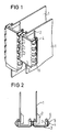
- FIG. 1 and 2 two electrical modules are inserted into a magazine, not shown.
- the assemblies have printed circuit boards 1 on which front panels 2 made of plastic are attached. Shield plates 3 are snapped onto the front panels.
- the substantially U-shaped curved shielding sheets 3 have holding tabs 4 and contact tabs 5 on their longitudinal sides in an alternating sequence, which tabs are produced by shearing and different bending.
- the contact tabs 5 protrude beyond the retaining tabs 4.
- the tabs are arranged in a mirror image on both long sides of the shield plate.
- the shield plate 3 extends over the entire length and width of the front panel 4.
- the contact tabs 5 are contacted with contact tabs 5 of the adjacent modules. As a result, the entire front of the fully equipped magazine is covered in a radio-frequency-tight manner.
- the retaining tabs 4 are angled perpendicular to the front of the modules.
- the free end of the retaining tabs 4 is bent towards the front panel 2 and engages behind it on a corresponding latching shoulder 6.
- the front panel 2 is provided with lateral bevels 7 for the retaining tabs 4.
- the side contact tabs 5 are bent back in a semicircle and protrude beyond the front panels 2 in the direction of the adjacent front panels to such an extent that they press resiliently against the contact tabs 5 of the adjacent shield plates 3. Due to the large number of contact tabs 5, there is thus a large-area contact between the shield plates 3.
Landscapes
- Engineering & Computer Science (AREA)
- Microelectronics & Electronic Packaging (AREA)
- Shielding Devices Or Components To Electric Or Magnetic Fields (AREA)
- Brushes (AREA)
- Input Circuits Of Receivers And Coupling Of Receivers And Audio Equipment (AREA)
- Housings And Mounting Of Transformers (AREA)
- Coupling Device And Connection With Printed Circuit (AREA)
- Motor Or Generator Frames (AREA)
Claims (11)
- Dispositif de blindage pour un module électrique pouvant être inseré dans un magasin à modules, constitué d'une tôle de contact en forme de bande, qui peut être fixée à la plaque avant (2) du module, qui s'étend dans la direction longitudinale de la plaque avant (2) et qui a une multiplicité de languettes élastiques de contact (5), qui s'étendent en direction de plaques avant voisines et qui peuvent établir un contact avec les parties de blindage des modules voisins, caractérisé par le fait que la tôle de contact, réalisée sous la forme d'une tôle de blindage (3), recouvre l'ensemble de la plaque avant (2) et peut établir un contact direct avec les deux tôles de blindage (3) des modules voisins.
- Dispositif de blindage suivant la revendication 1, caractérisé par le fait que les languettes ramifiées de contact (5) s'étendent le long d'un grand côté de la tôle de blindage (3) et les zones de contact antagonistes sont agencées de manière à ne pas être élastiques.
- Dispositif de blindage suivant la revendication 1 ou 2, caractérisé par le fait que les languettes de blindage (5) sont disposées sur les deux grands côtés de la tôle de blindage (3).
- Dispositif de blindage suivant la revendication 3, caractérisé par le fait qu'un contact réciproque peut être établi entre respectivement deux languettes de contact de tôles de blindage (3) voisines.
- Dispositif de blindage suivant la revendication 3, caractérisé par le fait que les languettes élastiques de contact (5) et des zones de contact non élastiques sont disposées selon une séquence alternée sur chaque côté longitudinal de la tôle de blindage (3), que respectivement une languette de contact (5) d'une tôle de blindage touche une zone de contact non élastique de la tôle de blindage voisine (3) et que les sections non élastiques sont plus larges que les languettes élastiques de contact (5).
- Dispositif de blindage suivant la revendication 5, caractérisé par le fait que dans une tôle de blindage (3), chaque languette de contact (5) est en vis-à-vis d'une zone de contact non élastique.
- Dispositif de blindage suivant la revendication 5 ou 6, caractérisé par le fait que les languettes de contact (5) sont disposées symétriquement, comme en un miroir, des deux côtés de la tôle de blindage (3).
- Dispositif de blindage suivant l'une des revendications précédentes, caractérisé par le fait que la tôle de blindage (3) peut être encliquetée sur le panneau avant (2) au moyen de languettes de retenue (4), dont les extrémités élastiques s'accrochent derrière la plaque avant (2).
- Dispositif de blindage suivant la revendication 8, caractérisé par le fait que les languettes de retenue (4) sont disposées dans les intervalles présents entre les languettes de contact (5).
- Dispositif de blindage suivant la revendication 9, caractérisé en ce que les languettes de retenue (4) sont utilisées en tant que zones de contact non élastiques.
- Dispositif de blindage suivant l'une des revendications précédentes, caractérisé par le fait que les languettes de contact (5) sont repliées sur elles-mêmes en forme de demi-cercle.
Priority Applications (8)
| Application Number | Priority Date | Filing Date | Title |
|---|---|---|---|
| EP89110472A EP0401418B1 (fr) | 1989-06-09 | 1989-06-09 | Dispositif de blindage pour un équipement électrique |
| ES89110472T ES2051924T3 (es) | 1989-06-09 | 1989-06-09 | Dispositivo de blindaje para un grupo constructivo electrico. |
| DE58907582T DE58907582D1 (de) | 1989-06-09 | 1989-06-09 | Schirmeinrichtung für eine elektrische Baugruppe. |
| AT8989110472T ATE105134T1 (de) | 1989-06-09 | 1989-06-09 | Schirmeinrichtung fuer eine elektrische baugruppe. |
| US07/527,429 US5083239A (en) | 1989-06-09 | 1990-05-23 | Shielding apparatus for an electrical assembly |
| CA002018457A CA2018457A1 (fr) | 1989-06-09 | 1990-06-07 | Dispositif de blindage pour systemes electriques |
| ZA904444A ZA904444B (en) | 1989-06-09 | 1990-06-08 | Shielding device for an electric module |
| AU57020/90A AU634783B2 (en) | 1989-06-09 | 1990-06-08 | Shielding device for an electric module |
Applications Claiming Priority (1)
| Application Number | Priority Date | Filing Date | Title |
|---|---|---|---|
| EP89110472A EP0401418B1 (fr) | 1989-06-09 | 1989-06-09 | Dispositif de blindage pour un équipement électrique |
Publications (2)
| Publication Number | Publication Date |
|---|---|
| EP0401418A1 EP0401418A1 (fr) | 1990-12-12 |
| EP0401418B1 true EP0401418B1 (fr) | 1994-04-27 |
Family
ID=8201483
Family Applications (1)
| Application Number | Title | Priority Date | Filing Date |
|---|---|---|---|
| EP89110472A Expired - Lifetime EP0401418B1 (fr) | 1989-06-09 | 1989-06-09 | Dispositif de blindage pour un équipement électrique |
Country Status (8)
| Country | Link |
|---|---|
| US (1) | US5083239A (fr) |
| EP (1) | EP0401418B1 (fr) |
| AT (1) | ATE105134T1 (fr) |
| AU (1) | AU634783B2 (fr) |
| CA (1) | CA2018457A1 (fr) |
| DE (1) | DE58907582D1 (fr) |
| ES (1) | ES2051924T3 (fr) |
| ZA (1) | ZA904444B (fr) |
Cited By (1)
| Publication number | Priority date | Publication date | Assignee | Title |
|---|---|---|---|---|
| DE19712146C2 (de) * | 1997-03-22 | 1999-02-11 | Aeg Intermas Gmbh | Anordnung zur hochfrequenzdichten Abschirmung |
Families Citing this family (17)
| Publication number | Priority date | Publication date | Assignee | Title |
|---|---|---|---|---|
| DE9012637U1 (de) * | 1990-09-04 | 1991-01-03 | Siemens AG, 8000 München | Steckverbinder für Rückwandverdrahtungen |
| DE4110800C1 (fr) * | 1991-04-04 | 1992-07-23 | Schroff Gmbh, 7541 Straubenhardt, De | |
| JP3011379B2 (ja) * | 1991-07-17 | 2000-02-21 | 北川工業株式会社 | 電磁波シールド用ガスケット |
| SE503484C2 (sv) * | 1994-04-11 | 1996-06-24 | Ericsson Telefon Ab L M | Kontaktfjäder |
| SE503467C2 (sv) * | 1994-12-14 | 1996-06-17 | Ericsson Telefon Ab L M | Jordnings- och skärmningsanordning |
| EP0809425A1 (fr) * | 1996-05-23 | 1997-11-26 | Elma Electronic Ag | Bac pour modules avec une face avant |
| EP0866650B1 (fr) * | 1997-03-22 | 2003-06-25 | Intermas-Elcom GmbH | Dispositif de blindage hautes fréquences |
| US6483024B1 (en) * | 2000-06-30 | 2002-11-19 | Silicon Graphics, Inc. | Panel gasket |
| US20040012940A1 (en) * | 2001-02-20 | 2004-01-22 | Kim David K.J. | Fault-tolerant assembly of printed circuit board |
| US6478170B1 (en) | 2001-06-08 | 2002-11-12 | Terraworx, Inc. | EMC sealed joint and a faceplate for use therewith |
| DE10137746C1 (de) * | 2001-08-01 | 2002-10-10 | Schroff Gmbh | Frontteil für elektronische Steckbaugruppen |
| US6977819B2 (en) * | 2001-09-21 | 2005-12-20 | Motorola, Inc. | Apparatus and method for electrically coupling a bezel |
| US7457134B2 (en) * | 2002-08-13 | 2008-11-25 | Finisar Corporation | Electromagnetic radiation containment system |
| US7258574B2 (en) * | 2004-09-30 | 2007-08-21 | International Business Machines Corporation | Snap-fit electromagnetic shield |
| US7671283B2 (en) * | 2005-01-20 | 2010-03-02 | Hewlett-Packard Development Company, L.P. | Apparatus for shielding electromagnetic radiation |
| TWI533780B (zh) * | 2013-09-05 | 2016-05-11 | 緯創資通股份有限公司 | 電子裝置及覆蓋結構 |
| CN106817887B (zh) * | 2015-11-30 | 2020-08-18 | 深圳富泰宏精密工业有限公司 | 屏蔽罩、屏蔽罩组件以及应用该屏蔽罩组件的电子装置 |
Family Cites Families (4)
| Publication number | Priority date | Publication date | Assignee | Title |
|---|---|---|---|---|
| GB1324560A (en) * | 1971-11-23 | 1973-07-25 | Standard Telephones Cables Ltd | Plug-in electrical component assemblies |
| FR2571922B1 (fr) * | 1984-10-17 | 1986-10-31 | Cit Alcatel | Chassis etanche aux perturbations electromagnetiques et joint electromagnetique |
| DE3604860C3 (de) * | 1986-02-15 | 1997-11-13 | Daimler Benz Aerospace Ag | Anordnung zur hochfrequenzdichten Abschirmung der Frontplatte eines Geräte-Einschubs |
| DE8803544U1 (de) * | 1988-03-16 | 1988-07-07 | Standard Elektrik Lorenz Ag, 7000 Stuttgart | Baugruppenträger mit abgeschirmten Steckbaugruppen |
-
1989
- 1989-06-09 DE DE58907582T patent/DE58907582D1/de not_active Expired - Fee Related
- 1989-06-09 AT AT8989110472T patent/ATE105134T1/de not_active IP Right Cessation
- 1989-06-09 EP EP89110472A patent/EP0401418B1/fr not_active Expired - Lifetime
- 1989-06-09 ES ES89110472T patent/ES2051924T3/es not_active Expired - Lifetime
-
1990
- 1990-05-23 US US07/527,429 patent/US5083239A/en not_active Expired - Fee Related
- 1990-06-07 CA CA002018457A patent/CA2018457A1/fr not_active Abandoned
- 1990-06-08 AU AU57020/90A patent/AU634783B2/en not_active Ceased
- 1990-06-08 ZA ZA904444A patent/ZA904444B/xx unknown
Cited By (1)
| Publication number | Priority date | Publication date | Assignee | Title |
|---|---|---|---|---|
| DE19712146C2 (de) * | 1997-03-22 | 1999-02-11 | Aeg Intermas Gmbh | Anordnung zur hochfrequenzdichten Abschirmung |
Also Published As
| Publication number | Publication date |
|---|---|
| ES2051924T3 (es) | 1994-07-01 |
| DE58907582D1 (de) | 1994-06-01 |
| AU634783B2 (en) | 1993-03-04 |
| US5083239A (en) | 1992-01-21 |
| ATE105134T1 (de) | 1994-05-15 |
| ZA904444B (en) | 1991-03-27 |
| EP0401418A1 (fr) | 1990-12-12 |
| AU5702090A (en) | 1990-12-13 |
| CA2018457A1 (fr) | 1990-12-09 |
Similar Documents
| Publication | Publication Date | Title |
|---|---|---|
| DE3039681C2 (de) | Elektromagnetische Abschirmvorrichtung für Elektronikschränke | |
| EP0401418A1 (fr) | Dispositif de blindage pour un équipement électrique | |
| DE2750088C2 (de) | Vorrichtung zur Abdichtung gegen elektromagnetische Strahlung | |
| EP0748486A1 (fr) | Carte enfichable pour appareils electroniques de traitement de donnees et son procede de fabrication et de montage | |
| DE3436119A1 (de) | Kontaktfederelement zum kontaktieren von leiterplatten | |
| WO2008034480A1 (fr) | Blindage | |
| WO1994014306A1 (fr) | Dispositif a support plastique permettant de loger et de maintenir un module electronique | |
| EP0828412B1 (fr) | Module haute fréquence, par exemple syntoniseur | |
| EP0822337A2 (fr) | Dispositif de montage pour un ventilateur électrique, en particulier pour un petit ventilateur | |
| DE19644414C1 (de) | Abgeschirmter Baugruppenträger | |
| WO2001069729A1 (fr) | Connexion par enfichage | |
| EP0402739B1 (fr) | Dispositif pour coupler électriquement des unités électriques enfichables | |
| EP1414283B1 (fr) | Système de controle muni de moyens de suppression de signaux d'interférence | |
| EP4231459A1 (fr) | Dispositif de raccordement et unité de raccordement | |
| EP0725987B1 (fr) | Connecteur de filtrage a fiches avec boitier de blindage | |
| DE19705173C2 (de) | Elektrisches Gerät | |
| DE102005046053B4 (de) | Elektrische Vorrichtung mit einer Leiterplatte und einem Bauteil | |
| DE7434817U (de) | Schaltungsplatte zum Einsetzen in Chassis oder chassisähnliche Trägerkörper von Steueranlagen | |
| EP0848451A2 (fr) | Dispositif pour la connexion électrique et mécanique de deux plaquettes à circuits imprimés disposées à distance l'une de l'autre ainsi qu'un appareil avec deux plaquettes à circuits imprimés disposées à distance l'une à l'autre connectées avec un tel dispositif | |
| DE4211923C1 (fr) | ||
| DE3737058C1 (en) | Housing for accommodating electrical telecommunications system assemblies | |
| DE102019134369B4 (de) | Leadframe für Drahtbauteile mit Kulissenstruktur | |
| EP0984515B1 (fr) | Connecteur électrique blindé | |
| DE3504080C2 (fr) | ||
| DE3626852C2 (fr) |
Legal Events
| Date | Code | Title | Description |
|---|---|---|---|
| PUAI | Public reference made under article 153(3) epc to a published international application that has entered the european phase |
Free format text: ORIGINAL CODE: 0009012 |
|
| AK | Designated contracting states |
Kind code of ref document: A1 Designated state(s): AT BE CH DE ES FR GB GR IT LI LU NL SE |
|
| 17P | Request for examination filed |
Effective date: 19901220 |
|
| 17Q | First examination report despatched |
Effective date: 19930812 |
|
| GRAA | (expected) grant |
Free format text: ORIGINAL CODE: 0009210 |
|
| AK | Designated contracting states |
Kind code of ref document: B1 Designated state(s): AT BE CH DE ES FR GB GR IT LI LU NL SE |
|
| REF | Corresponds to: |
Ref document number: 105134 Country of ref document: AT Date of ref document: 19940515 Kind code of ref document: T |
|
| REF | Corresponds to: |
Ref document number: 58907582 Country of ref document: DE Date of ref document: 19940601 |
|
| PGFP | Annual fee paid to national office [announced via postgrant information from national office to epo] |
Ref country code: SE Payment date: 19940613 Year of fee payment: 6 |
|
| PGFP | Annual fee paid to national office [announced via postgrant information from national office to epo] |
Ref country code: GR Payment date: 19940617 Year of fee payment: 6 |
|
| PGFP | Annual fee paid to national office [announced via postgrant information from national office to epo] |
Ref country code: NL Payment date: 19940630 Year of fee payment: 6 Ref country code: LU Payment date: 19940630 Year of fee payment: 6 |
|
| REG | Reference to a national code |
Ref country code: ES Ref legal event code: FG2A Ref document number: 2051924 Country of ref document: ES Kind code of ref document: T3 |
|
| ITF | It: translation for a ep patent filed | ||
| EPTA | Lu: last paid annual fee | ||
| REG | Reference to a national code |
Ref country code: GR Ref legal event code: FG4A Free format text: 3011845 |
|
| GBT | Gb: translation of ep patent filed (gb section 77(6)(a)/1977) |
Effective date: 19940704 |
|
| ET | Fr: translation filed | ||
| EAL | Se: european patent in force in sweden |
Ref document number: 89110472.1 |
|
| PLBE | No opposition filed within time limit |
Free format text: ORIGINAL CODE: 0009261 |
|
| STAA | Information on the status of an ep patent application or granted ep patent |
Free format text: STATUS: NO OPPOSITION FILED WITHIN TIME LIMIT |
|
| 26N | No opposition filed | ||
| PG25 | Lapsed in a contracting state [announced via postgrant information from national office to epo] |
Ref country code: LU Free format text: LAPSE BECAUSE OF NON-PAYMENT OF DUE FEES Effective date: 19950609 |
|
| PG25 | Lapsed in a contracting state [announced via postgrant information from national office to epo] |
Ref country code: SE Effective date: 19950610 |
|
| PGFP | Annual fee paid to national office [announced via postgrant information from national office to epo] |
Ref country code: DE Payment date: 19950818 Year of fee payment: 7 |
|
| PGFP | Annual fee paid to national office [announced via postgrant information from national office to epo] |
Ref country code: CH Payment date: 19950913 Year of fee payment: 7 |
|
| PG25 | Lapsed in a contracting state [announced via postgrant information from national office to epo] |
Ref country code: GR Free format text: THE PATENT HAS BEEN ANNULLED BY A DECISION OF A NATIONAL AUTHORITY Effective date: 19951231 |
|
| PG25 | Lapsed in a contracting state [announced via postgrant information from national office to epo] |
Ref country code: NL Effective date: 19960101 |
|
| REG | Reference to a national code |
Ref country code: GR Ref legal event code: MM2A Free format text: 3011845 |
|
| NLV4 | Nl: lapsed or anulled due to non-payment of the annual fee |
Effective date: 19960101 |
|
| EUG | Se: european patent has lapsed |
Ref document number: 89110472.1 |
|
| PGFP | Annual fee paid to national office [announced via postgrant information from national office to epo] |
Ref country code: GB Payment date: 19960523 Year of fee payment: 8 |
|
| PGFP | Annual fee paid to national office [announced via postgrant information from national office to epo] |
Ref country code: AT Payment date: 19960530 Year of fee payment: 8 |
|
| PGFP | Annual fee paid to national office [announced via postgrant information from national office to epo] |
Ref country code: ES Payment date: 19960611 Year of fee payment: 8 |
|
| PGFP | Annual fee paid to national office [announced via postgrant information from national office to epo] |
Ref country code: BE Payment date: 19960612 Year of fee payment: 8 |
|
| PGFP | Annual fee paid to national office [announced via postgrant information from national office to epo] |
Ref country code: FR Payment date: 19960625 Year of fee payment: 8 |
|
| PG25 | Lapsed in a contracting state [announced via postgrant information from national office to epo] |
Ref country code: LI Effective date: 19960630 Ref country code: CH Effective date: 19960630 |
|
| REG | Reference to a national code |
Ref country code: CH Ref legal event code: PL |
|
| PG25 | Lapsed in a contracting state [announced via postgrant information from national office to epo] |
Ref country code: DE Effective date: 19970301 |
|
| PG25 | Lapsed in a contracting state [announced via postgrant information from national office to epo] |
Ref country code: GB Free format text: LAPSE BECAUSE OF NON-PAYMENT OF DUE FEES Effective date: 19970609 Ref country code: AT Effective date: 19970609 |
|
| PG25 | Lapsed in a contracting state [announced via postgrant information from national office to epo] |
Ref country code: ES Free format text: LAPSE BECAUSE OF NON-PAYMENT OF DUE FEES Effective date: 19970610 |
|
| PG25 | Lapsed in a contracting state [announced via postgrant information from national office to epo] |
Ref country code: BE Effective date: 19970630 |
|
| BERE | Be: lapsed |
Owner name: SIEMENS A.G. Effective date: 19970630 |
|
| GBPC | Gb: european patent ceased through non-payment of renewal fee |
Effective date: 19970609 |
|
| PG25 | Lapsed in a contracting state [announced via postgrant information from national office to epo] |
Ref country code: FR Free format text: LAPSE BECAUSE OF NON-PAYMENT OF DUE FEES Effective date: 19980227 |
|
| REG | Reference to a national code |
Ref country code: FR Ref legal event code: ST |
|
| REG | Reference to a national code |
Ref country code: FR Ref legal event code: ST |
|
| REG | Reference to a national code |
Ref country code: ES Ref legal event code: FD2A Effective date: 20000403 |
|
| PG25 | Lapsed in a contracting state [announced via postgrant information from national office to epo] |
Ref country code: IT Free format text: LAPSE BECAUSE OF NON-PAYMENT OF DUE FEES Effective date: 20050609 |