EP0822337A2 - Dispositif de montage pour un ventilateur électrique, en particulier pour un petit ventilateur - Google Patents
Dispositif de montage pour un ventilateur électrique, en particulier pour un petit ventilateur Download PDFInfo
- Publication number
- EP0822337A2 EP0822337A2 EP97112924A EP97112924A EP0822337A2 EP 0822337 A2 EP0822337 A2 EP 0822337A2 EP 97112924 A EP97112924 A EP 97112924A EP 97112924 A EP97112924 A EP 97112924A EP 0822337 A2 EP0822337 A2 EP 0822337A2
- Authority
- EP
- European Patent Office
- Prior art keywords
- fan
- holding
- holding device
- holding part
- mounting
- Prior art date
- Legal status (The legal status is an assumption and is not a legal conclusion. Google has not performed a legal analysis and makes no representation as to the accuracy of the status listed.)
- Granted
Links
Images


Classifications
-
- F—MECHANICAL ENGINEERING; LIGHTING; HEATING; WEAPONS; BLASTING
- F04—POSITIVE - DISPLACEMENT MACHINES FOR LIQUIDS; PUMPS FOR LIQUIDS OR ELASTIC FLUIDS
- F04D—NON-POSITIVE-DISPLACEMENT PUMPS
- F04D29/00—Details, component parts, or accessories
- F04D29/60—Mounting; Assembling; Disassembling
- F04D29/601—Mounting; Assembling; Disassembling specially adapted for elastic fluid pumps
Definitions
- the present invention relates to a holding device for holding an electric fan, in particular Mini fan, on a mounting wall.
- Fan or its fan housing which in connection with of the present invention have at least two, but usually four through mounting holes with a course parallel to the fan axis.
- the fan housing has - in an axial view seen - a rectangular or square contour, being A continuous mounting hole is arranged in each corner area is.
- mounting brackets it is known to use mounting brackets to use.
- One angle leg each attached to the fan by screws while the other Angle legs on the mounting wall usually also is screwed tight.
- For screw fastening on the fan side insert nuts or so-called sheet metal nuts arranged in which the fastening screws intervention.
- U-shaped bracket has two Legs each with an internal thread (nut) Screw opening.
- This fastener can only be used for fans whose housing at least two spaced apart in the area of the mounting holes Have flanges with each mounting hole practical consists of two aligned partial holes in the flanges.
- the U-shaped bracket is thus between the flanges used that in the area of each partial hole one of the two screw holes is arranged.
- the bracket is so resilient that it jams between the flanges is held.
- the present invention has for its object a To create a holding device with which the mounting bracket of a fan is significantly simplified.
- a Holding device reached, consisting of at least one, in essentially flat, one-sided fan system level defining holding part, the holding part at least an approximately perpendicular to the investment plane of the Holding part protruding and to the bracket connection force and / or can be positively inserted into a mounting hole in the fan Plug-in element and at least one pin-like, in an orientation approximately perpendicular to the plug element protruding from the holding part, for attachment by a Has hole of the mounting wall feasible fastener.
- the invention thus advantageously eliminates any Screw connection, because the holding part according to the invention needs with its plug-in element only in the respective Mounting hole to be inserted.
- the plug element By a suitable design of the plug element a good force and / or positive connection for sufficient mounting can be achieved.
- the Plug element has barb-like, elastic holding tongues, that when inserted in the hole wall of the mounting hole claw that a subsequent pulling out is almost impossible.
- a good and safe claw is mainly used in plastic Fan housings reached, but the invention is suitable basically also for metal housings. In both cases but it is advantageous if the holding part according to the invention itself made of metal, preferably sheet metal.
- the pin or (flat) plug-like fastening element For mounting on or on the mounting wall only needs the pin or (flat) plug-like fastening element passed through a hole in the mounting wall and then on suitable way to be fixed.
- This fixation can in simplest case due to plastic deformation, e.g. by bending and / or entangling the fastener on the opposite side of the fan Assembly wall done. This is a positive Attachment reached. It is also possible to use the fastener to connect with the assembly wall, especially to solder or glue.
- the holding device from two - in particular identical - Holding parts, which are arranged in certain areas of the fan housing on its two faces attached via preferably two plug elements will.
- Each points to the mounting on the mounting wall Holding element preferably also two fasteners on. There are thus a total of four fastening elements present in corresponding holes in the mounting wall are insertable. This execution leads to a very secure and firm bracket.
- the Holding parts - in addition to their mechanical holding function - advantageously at the same time for electrical Connection of the fan.
- the two holding parts consist of an electrically conductive material, especially sheet metal, while the fan housing is off an electrically insulating material (plastic), a short circuit between the live Exclude holding parts.
- the electrical connection is made preferably directly to a mounting wall Acting circuit board by the inserted fasteners of the holding parts with corresponding conductor tracks to be soldered. This can easily be done in one Solder bath, if necessary together with the soldering further electronic components. The fan then needs only to be electrically connected with the holding parts.
- each holding part preferably has at least one electrical connection element on which a supply conductor (Connecting wire) of the fan can be connected.
- This Embodiment also simplifies the electrical connection of the fan considerably.
- the supply managers can already after attaching the two holding parts to their connecting elements be connected.
- Below is at the mechanical connection of the holding parts to the circuit board at the same time - in just one operation - even that electrical connection made. this leads to a serious simplification of the assembly of the fan, i.e. the mechanical bracket and the electrical connection.
- the fan forms together with the invention Holding parts a pre-assembled unit, which - analog to other (electronic) components - to populate the PCB can be handled very easily.
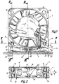
- Fig. 1 is to be attached of a fan 1 on a mounting wall 2 according to the invention Holding device 4 is provided.
- the fan 1 is shown greatly enlarged in Fig. 1, it is especially a small fan, whose fan housing 6 for example a square contour with an edge length of approx. 40 x 40 mm.
- the invention is by no means limited to this. It can also - as shown - around an axial fan, but alternatively also act as a radial fan.
- the holding device 4 consists of two advantageously identical holding parts 10.Each holding part 10 is essentially flat and defines one-sided with a part of its surface a fan system level 12.
- the holding part 10 preferably has in this area two projecting approximately perpendicular to the contact plane 12 Plug-in elements 14, the force and / or to the bracket connection positively in each one mounting hole 16 of the Fan 1 or the fan housing 6 can be inserted.
- Each Mounting hole 16 extends parallel to the fan axis 18, which also applies accordingly to the plug elements 14. Consequently, the holding parts 10 are parallel to each other and perpendicular to the fan axis 18 and to the mounting wall 2 Levels. 2, 4 and 4a extend the Plug elements 14 of the two holding parts 10 each from opposite End faces of the fan 1 in the mounting holes 16.
- Each holding part 10 also preferably has two pin-like, in an approximately perpendicular to the plug elements 14 Alignment and pointing away from the holding part 10 protruding, for attachment through a hole 20 each Mounting wall 2 feasible fasteners 22.
- the fan 1 About the holding device 4 according to the invention
- Mounting wall 2 attachable that its fan axis 18th runs parallel to the plane of the mounting wall 2.
- each holding part 10 preferably as a one-piece stamped and bent part made of sheet metal.
- the holding part 10 preferably has one elongated, essentially rectangular surface shape, wherein the plug elements 14 on one upper longitudinal edge 24 and the fasteners on the other, lower longitudinal edge 26 and here in particular on the narrow sides 28 adjacent corner areas are arranged.
- the plug elements 14 on one upper longitudinal edge 24 and the fasteners on the other, lower longitudinal edge 26 and here in particular on the narrow sides 28 adjacent corner areas are arranged.
- this shows Holding part 10 on its lower longitudinal edge 26 at least one, but preferably two each adjacent to the fasteners 22 arranged support elements 32.
- This Support elements 32 arrive after the fastening elements have been inserted 22 in the holes 20 of the mounting wall 2 to rest on the mounting wall 2; thus they form practically support feet (see Fig. 1).
- each plug element 14 has two elastic, barb-like retaining tongues 34, which are after insertion of the plug element 14 in the respective mounting hole 16 of the fan 1 in the hole wall of the mounting hole 16 claw.
- each plug-in element is U-shaped Cross section with an upper U-web wall 36 and formed two side U-leg walls 38, wherein the retaining tongues 34 from the two leg walls 38 punched out and diagonally outwards and back towards the investment level 12 are curved.
- the web wall 36 is in one piece via a bent connecting section 40 with the upper longitudinal edge 24 of the flat part of the holding part 10 connected.
- each fastener 22nd preferably as a punched out narrow strip of material formed, this strip of material expediently lies in the plane of the holding part 10.
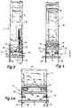
- each holding part 10 has at least a connecting element 42 for electrical connection a supply conductor 44 of the fan 1 (see Fig. 3).
- Each connection element 42 is in one Surface area of the holding part 10 arranged in the assembled Condition - see in particular Fig. 4 - a distance A and thus a free space 46 between the fan 1, the Mounting wall 2 and the two opposite holding parts 10 defined.
- Each connection element is expedient 42 in one piece from the material of the holding part 10, in particular formed by punching and bending and preferably extends away from the fan system side in the open space 46.
- the holding part has 10 as a connecting element 42 at least one clamping cutting connector 48, but preferably two in parallel, spaced apart clamping cutting connector 48.
- the is paired arrangement of two clamping cutting connectors 48 advantageous in so far as a connecting conductor can be inserted simultaneously into both clamping cutting connectors 48 which makes good electrical contacting (high contact reliability) and also a good fixation of position and direction of the connecting conductor 44 is reached.
- each clamping cutting connector 48 in a narrowing insertion slot in a manner known per se 50 for the connecting conductor 44.
- the holding part has a connection element 42 on the one hand Solder tail or solder eyelet 52 and on the other hand additionally one Crimp connector 54 on. 11, the solder tail 52 also punched out of the holding part 10 and bent through 90 °. It has an especially elongated hole 56 for Execution of the connecting conductor 44. 12 the crimp connector 54 consists of a holding portion 54a for the isolation of the connecting conductor 44 and from a Contact section 54b for a stripped end of the connecting conductor 44.
- connection elements 42 can be in any combination and number be applied. The user then has the option of choose a connection type that suits him.
- each plug-in element 14 has one from the fan installation level 12 from measured insertion length, which in any case significantly smaller than half the total length of the respective mounting hole 16 must be.
- the holding parts 10 according to the invention can also be connected serve the existing motor windings.
- the invention is not based on the illustrated and described Embodiments limited, but also includes all designs having the same effect in the sense of the invention.
- the invention is not yet based on the Claim 1 defined combination of features limited, but can also be by any other combination of certain characteristics of all of the individual characteristics disclosed be defined. This means that basically practically every single feature of claim 1 omitted or by at least one elsewhere in the registration disclosed individual feature can be replaced. To that extent is claim 1 only as a first attempt at formulation to understand for an invention.
Landscapes
- Engineering & Computer Science (AREA)
- Mechanical Engineering (AREA)
- General Engineering & Computer Science (AREA)
- Structures Of Non-Positive Displacement Pumps (AREA)
- Cooling Or The Like Of Electrical Apparatus (AREA)
Applications Claiming Priority (2)
| Application Number | Priority Date | Filing Date | Title |
|---|---|---|---|
| DE29613278U | 1996-07-31 | ||
| DE29613278 | 1996-07-31 |
Publications (3)
| Publication Number | Publication Date |
|---|---|
| EP0822337A2 true EP0822337A2 (fr) | 1998-02-04 |
| EP0822337A3 EP0822337A3 (fr) | 1998-10-14 |
| EP0822337B1 EP0822337B1 (fr) | 2003-05-07 |
Family
ID=8027246
Family Applications (1)
| Application Number | Title | Priority Date | Filing Date |
|---|---|---|---|
| EP97112924A Expired - Lifetime EP0822337B1 (fr) | 1996-07-31 | 1997-07-28 | Dispositif de montage pour un ventilateur électrique, en particulier pour un petit ventilateur |
Country Status (4)
| Country | Link |
|---|---|
| US (1) | US5924849A (fr) |
| EP (1) | EP0822337B1 (fr) |
| AT (1) | ATE239873T1 (fr) |
| DE (3) | DE19731411A1 (fr) |
Cited By (1)
| Publication number | Priority date | Publication date | Assignee | Title |
|---|---|---|---|---|
| EP1463397A3 (fr) * | 2003-03-25 | 2006-03-01 | Papst-Motoren GmbH & Co. KG | Element de fixation pour des petits ventilateurs |
Families Citing this family (11)
| Publication number | Priority date | Publication date | Assignee | Title |
|---|---|---|---|---|
| US6000919A (en) * | 1999-02-17 | 1999-12-14 | Hsieh; Hsin-Mao | Fan with reduced thickness |
| JP2003009457A (ja) * | 2001-06-18 | 2003-01-10 | Nidec Copal Corp | 軸流ファンモータ |
| EP1458078A1 (fr) * | 2003-02-15 | 2004-09-15 | ebm-papst St. Georgen GmbH & Co. KG | Arrangement avec un moteur éléctrique et un méthode de fabrication de cet arrangement |
| EP1526287B1 (fr) | 2003-10-21 | 2005-12-14 | ebm-papst St. Georgen GmbH & Co. KG | Ventilateur avec élément de fixation et procédé pour son montage |
| EP1747378B1 (fr) * | 2004-03-30 | 2010-10-20 | ebm-papst St. Georgen GmbH & Co. KG | Ensemble ventilateur |
| DE102005039265A1 (de) | 2005-08-19 | 2007-02-22 | Hirschmann Car Communication Gmbh | Befestigung eines Lüfters für ein elektronisches Gerät |
| ATE449912T1 (de) * | 2005-08-19 | 2009-12-15 | Ebm Papst St Georgen Gmbh & Co | Lüfter |
| TWI299116B (en) * | 2006-05-22 | 2008-07-21 | Delta Electronics Inc | Fan assembly and its fastening structure |
| US20140341760A1 (en) * | 2013-05-14 | 2014-11-20 | Asia Vital Components (China) Co., Ltd. | Fan structure with externally connected circuit |
| JP6104134B2 (ja) * | 2013-09-13 | 2017-03-29 | 山洋電気株式会社 | ファンモータの筐体 |
| CN119072839B (zh) * | 2024-02-07 | 2025-03-07 | 马渊马达株式会社 | 鼓风机外壳、鼓风机布线构造以及鼓风机 |
Family Cites Families (10)
| Publication number | Priority date | Publication date | Assignee | Title |
|---|---|---|---|---|
| US2594688A (en) * | 1950-02-17 | 1952-04-29 | Dearborn Stove Company | Hinged door and motor support for window coolers |
| US3506226A (en) * | 1968-06-25 | 1970-04-14 | Minnesota Mining & Mfg | Vibration isolating motor bracket |
| DE3809627A1 (de) * | 1988-03-22 | 1989-10-05 | Semperit Ag Holding | Montagemodul fuer geblaese |
| JPH02266597A (ja) * | 1989-04-07 | 1990-10-31 | Hitachi Ltd | ファン |
| DE9209165U1 (de) * | 1992-07-08 | 1992-08-27 | Siemens AG, 8000 München | Halterung für einen Axiallüfter in einem Baugruppenträger |
| JPH0697687A (ja) * | 1992-09-10 | 1994-04-08 | Pfu Ltd | 電子機器における冷却ファンの取付構造 |
| US5297929A (en) * | 1992-12-30 | 1994-03-29 | Alex Horng | Super thin small heat dispersing fan |
| JPH07176882A (ja) * | 1993-12-17 | 1995-07-14 | Pfu Ltd | 冷却ファンの実装構造 |
| US5478221A (en) * | 1994-01-31 | 1995-12-26 | Lzr Electronics, Inc. | Miniature fan for printed circuit board |
| JP3188397B2 (ja) * | 1996-07-04 | 2001-07-16 | 松下電器産業株式会社 | 送風装置 |
-
1997
- 1997-07-22 DE DE19731411A patent/DE19731411A1/de not_active Withdrawn
- 1997-07-22 DE DE29712967U patent/DE29712967U1/de not_active Expired - Lifetime
- 1997-07-28 AT AT97112924T patent/ATE239873T1/de not_active IP Right Cessation
- 1997-07-28 DE DE59710020T patent/DE59710020D1/de not_active Expired - Lifetime
- 1997-07-28 EP EP97112924A patent/EP0822337B1/fr not_active Expired - Lifetime
- 1997-07-31 US US08/903,863 patent/US5924849A/en not_active Expired - Fee Related
Cited By (2)
| Publication number | Priority date | Publication date | Assignee | Title |
|---|---|---|---|---|
| EP1463397A3 (fr) * | 2003-03-25 | 2006-03-01 | Papst-Motoren GmbH & Co. KG | Element de fixation pour des petits ventilateurs |
| EP1684563A1 (fr) * | 2003-03-25 | 2006-07-26 | ebm-papst St. Georgen GmbH & Co. KG | Élément de rétention pour de petits ventilateurs |
Also Published As
| Publication number | Publication date |
|---|---|
| EP0822337B1 (fr) | 2003-05-07 |
| EP0822337A3 (fr) | 1998-10-14 |
| US5924849A (en) | 1999-07-20 |
| ATE239873T1 (de) | 2003-05-15 |
| DE59710020D1 (de) | 2003-06-12 |
| DE19731411A1 (de) | 1998-02-05 |
| DE29712967U1 (de) | 1997-09-18 |
Similar Documents
| Publication | Publication Date | Title |
|---|---|---|
| EP3159974B1 (fr) | Borne d'alimentation électrique | |
| DE69300865T3 (de) | Elektrischer verbinder mit blech als steckkontaktmaterial. | |
| DE60004418T2 (de) | Abzweigverbindergehäuse | |
| EP0212330B1 (fr) | Borne de jonction ou serre-fil pour appareils électriques | |
| EP0735615A2 (fr) | Borne de jonction pour appareils électriques | |
| DE102010014144A1 (de) | Elektrische Anschlussklemme | |
| DE2460704A1 (de) | Elektrischer kontakt | |
| EP3375048B1 (fr) | Contact à enficher | |
| DE102009019699B4 (de) | Anschlussklemme für Leiterplatten | |
| EP0822337B1 (fr) | Dispositif de montage pour un ventilateur électrique, en particulier pour un petit ventilateur | |
| DE3441416C2 (de) | Elektrische Steckverbindung | |
| DE4000548A1 (de) | Steckerleiste | |
| EP0828320A1 (fr) | Connecteur | |
| DE10218567A1 (de) | Anschlusssystem | |
| EP1182735B1 (fr) | Réglette d'interconnexion électrique | |
| EP4231459A1 (fr) | Dispositif de raccordement et unité de raccordement | |
| DE29623742U1 (de) | Elektrischer Steckverbinder, insbesondere für Leiterplatten | |
| EP0534063A2 (fr) | Réglette de raccordement pour des plaquettes de circuits imprimés | |
| DE102004031949B4 (de) | Elektrischer Steckverbinder | |
| DE9208702U1 (de) | Filter-Steckverbinder mit Schirmgehäuse | |
| DE102005010704B4 (de) | Federbuchse für Miniatur-Steckverbinder | |
| DE102019134369B4 (de) | Leadframe für Drahtbauteile mit Kulissenstruktur | |
| EP0560261A1 (fr) | Dispositif pour le maintien de plaques de circuit dans un boîtier | |
| DE102006000958A1 (de) | Elektrisches Gerät | |
| EP0123040A2 (fr) | Plaque à bornes pour des appareils électriques ou électroniques, par exemple pour un interrupteur de protection contre la surintensité |
Legal Events
| Date | Code | Title | Description |
|---|---|---|---|
| PUAI | Public reference made under article 153(3) epc to a published international application that has entered the european phase |
Free format text: ORIGINAL CODE: 0009012 |
|
| AK | Designated contracting states |
Kind code of ref document: A2 Designated state(s): AT DE ES FR GB IE IT NL |
|
| PUAL | Search report despatched |
Free format text: ORIGINAL CODE: 0009013 |
|
| RHK1 | Main classification (correction) | ||
| RHK1 | Main classification (correction) |
Ipc: F04D 29/60 |
|
| AK | Designated contracting states |
Kind code of ref document: A3 Designated state(s): AT BE CH DE DK ES FI FR GB GR IE IT LI LU MC NL PT SE |
|
| 17P | Request for examination filed |
Effective date: 19990303 |
|
| AKX | Designation fees paid |
Free format text: AT DE ES FR GB IE IT NL |
|
| GRAH | Despatch of communication of intention to grant a patent |
Free format text: ORIGINAL CODE: EPIDOS IGRA |
|
| GRAH | Despatch of communication of intention to grant a patent |
Free format text: ORIGINAL CODE: EPIDOS IGRA |
|
| GRAA | (expected) grant |
Free format text: ORIGINAL CODE: 0009210 |
|
| AK | Designated contracting states |
Designated state(s): AT DE ES FR GB IE IT NL |
|
| PG25 | Lapsed in a contracting state [announced via postgrant information from national office to epo] |
Ref country code: NL Free format text: LAPSE BECAUSE OF FAILURE TO SUBMIT A TRANSLATION OF THE DESCRIPTION OR TO PAY THE FEE WITHIN THE PRESCRIBED TIME-LIMIT Effective date: 20030507 Ref country code: IE Free format text: LAPSE BECAUSE OF FAILURE TO SUBMIT A TRANSLATION OF THE DESCRIPTION OR TO PAY THE FEE WITHIN THE PRESCRIBED TIME-LIMIT Effective date: 20030507 |
|
| REG | Reference to a national code |
Ref country code: GB Ref legal event code: FG4D Free format text: NOT ENGLISH |
|
| REG | Reference to a national code |
Ref country code: IE Ref legal event code: FG4D Free format text: GERMAN |
|
| REF | Corresponds to: |
Ref document number: 59710020 Country of ref document: DE Date of ref document: 20030612 Kind code of ref document: P |
|
| GBT | Gb: translation of ep patent filed (gb section 77(6)(a)/1977) | ||
| PG25 | Lapsed in a contracting state [announced via postgrant information from national office to epo] |
Ref country code: AT Free format text: LAPSE BECAUSE OF NON-PAYMENT OF DUE FEES Effective date: 20030728 |
|
| PG25 | Lapsed in a contracting state [announced via postgrant information from national office to epo] |
Ref country code: ES Free format text: LAPSE BECAUSE OF FAILURE TO SUBMIT A TRANSLATION OF THE DESCRIPTION OR TO PAY THE FEE WITHIN THE PRESCRIBED TIME-LIMIT Effective date: 20030818 |
|
| NLV1 | Nl: lapsed or annulled due to failure to fulfill the requirements of art. 29p and 29m of the patents act | ||
| REG | Reference to a national code |
Ref country code: IE Ref legal event code: FD4D Ref document number: 0822337E Country of ref document: IE |
|
| ET | Fr: translation filed | ||
| PLBE | No opposition filed within time limit |
Free format text: ORIGINAL CODE: 0009261 |
|
| STAA | Information on the status of an ep patent application or granted ep patent |
Free format text: STATUS: NO OPPOSITION FILED WITHIN TIME LIMIT |
|
| 26N | No opposition filed |
Effective date: 20040210 |
|
| PGFP | Annual fee paid to national office [announced via postgrant information from national office to epo] |
Ref country code: FR Payment date: 20100616 Year of fee payment: 14 |
|
| PGFP | Annual fee paid to national office [announced via postgrant information from national office to epo] |
Ref country code: IT Payment date: 20100330 Year of fee payment: 14 |
|
| PGFP | Annual fee paid to national office [announced via postgrant information from national office to epo] |
Ref country code: DE Payment date: 20100701 Year of fee payment: 14 |
|
| PGFP | Annual fee paid to national office [announced via postgrant information from national office to epo] |
Ref country code: GB Payment date: 20100709 Year of fee payment: 14 |
|
| GBPC | Gb: european patent ceased through non-payment of renewal fee |
Effective date: 20110728 |
|
| REG | Reference to a national code |
Ref country code: FR Ref legal event code: ST Effective date: 20120330 |
|
| PG25 | Lapsed in a contracting state [announced via postgrant information from national office to epo] |
Ref country code: FR Free format text: LAPSE BECAUSE OF NON-PAYMENT OF DUE FEES Effective date: 20110801 Ref country code: DE Free format text: LAPSE BECAUSE OF NON-PAYMENT OF DUE FEES Effective date: 20120201 |
|
| REG | Reference to a national code |
Ref country code: DE Ref legal event code: R119 Ref document number: 59710020 Country of ref document: DE Effective date: 20120201 |
|
| PG25 | Lapsed in a contracting state [announced via postgrant information from national office to epo] |
Ref country code: IT Free format text: LAPSE BECAUSE OF NON-PAYMENT OF DUE FEES Effective date: 20110728 |
|
| PG25 | Lapsed in a contracting state [announced via postgrant information from national office to epo] |
Ref country code: GB Free format text: LAPSE BECAUSE OF NON-PAYMENT OF DUE FEES Effective date: 20110728 |