EP0401422A1 - Machine de remplissage et d'emballage - Google Patents
Machine de remplissage et d'emballage Download PDFInfo
- Publication number
- EP0401422A1 EP0401422A1 EP89114766A EP89114766A EP0401422A1 EP 0401422 A1 EP0401422 A1 EP 0401422A1 EP 89114766 A EP89114766 A EP 89114766A EP 89114766 A EP89114766 A EP 89114766A EP 0401422 A1 EP0401422 A1 EP 0401422A1
- Authority
- EP
- European Patent Office
- Prior art keywords
- film tube
- parts
- machine according
- guide
- bolt
- Prior art date
- Legal status (The legal status is an assumption and is not a legal conclusion. Google has not performed a legal analysis and makes no representation as to the accuracy of the status listed.)
- Granted
Links
- 238000004806 packaging method and process Methods 0.000 title claims abstract description 15
- 230000006835 compression Effects 0.000 claims description 9
- 238000007906 compression Methods 0.000 claims description 9
- 238000005096 rolling process Methods 0.000 claims description 9
- 238000003466 welding Methods 0.000 claims description 6
- 230000002093 peripheral effect Effects 0.000 claims description 3
- 238000010438 heat treatment Methods 0.000 claims description 2
- 239000007788 liquid Substances 0.000 description 15
- 238000011161 development Methods 0.000 description 4
- 230000018109 developmental process Effects 0.000 description 4
- 210000005069 ears Anatomy 0.000 description 4
- 239000011888 foil Substances 0.000 description 2
- 238000007373 indentation Methods 0.000 description 1
- 239000000463 material Substances 0.000 description 1
- 238000000034 method Methods 0.000 description 1
- 238000000465 moulding Methods 0.000 description 1
- 230000002123 temporal effect Effects 0.000 description 1
Images

Classifications
-
- B—PERFORMING OPERATIONS; TRANSPORTING
- B29—WORKING OF PLASTICS; WORKING OF SUBSTANCES IN A PLASTIC STATE IN GENERAL
- B29C—SHAPING OR JOINING OF PLASTICS; SHAPING OF MATERIAL IN A PLASTIC STATE, NOT OTHERWISE PROVIDED FOR; AFTER-TREATMENT OF THE SHAPED PRODUCTS, e.g. REPAIRING
- B29C66/00—General aspects of processes or apparatus for joining preformed parts
- B29C66/80—General aspects of machine operations or constructions and parts thereof
- B29C66/83—General aspects of machine operations or constructions and parts thereof characterised by the movement of the joining or pressing tools
- B29C66/834—General aspects of machine operations or constructions and parts thereof characterised by the movement of the joining or pressing tools moving with the parts to be joined
- B29C66/8351—Jaws mounted on rollers, cylinders, drums, bands, belts or chains; Flying jaws
- B29C66/83511—Jaws mounted on rollers, cylinders, drums, bands, belts or chains; Flying jaws jaws mounted on rollers, cylinders or drums
- B29C66/83513—Jaws mounted on rollers, cylinders, drums, bands, belts or chains; Flying jaws jaws mounted on rollers, cylinders or drums cooperating jaws mounted on rollers, cylinders or drums and moving in a closed path
-
- B—PERFORMING OPERATIONS; TRANSPORTING
- B29—WORKING OF PLASTICS; WORKING OF SUBSTANCES IN A PLASTIC STATE IN GENERAL
- B29C—SHAPING OR JOINING OF PLASTICS; SHAPING OF MATERIAL IN A PLASTIC STATE, NOT OTHERWISE PROVIDED FOR; AFTER-TREATMENT OF THE SHAPED PRODUCTS, e.g. REPAIRING
- B29C65/00—Joining or sealing of preformed parts, e.g. welding of plastics materials; Apparatus therefor
- B29C65/02—Joining or sealing of preformed parts, e.g. welding of plastics materials; Apparatus therefor by heating, with or without pressure
- B29C65/18—Joining or sealing of preformed parts, e.g. welding of plastics materials; Apparatus therefor by heating, with or without pressure using heated tools
-
- B—PERFORMING OPERATIONS; TRANSPORTING
- B29—WORKING OF PLASTICS; WORKING OF SUBSTANCES IN A PLASTIC STATE IN GENERAL
- B29C—SHAPING OR JOINING OF PLASTICS; SHAPING OF MATERIAL IN A PLASTIC STATE, NOT OTHERWISE PROVIDED FOR; AFTER-TREATMENT OF THE SHAPED PRODUCTS, e.g. REPAIRING
- B29C66/00—General aspects of processes or apparatus for joining preformed parts
- B29C66/01—General aspects dealing with the joint area or with the area to be joined
- B29C66/05—Particular design of joint configurations
- B29C66/10—Particular design of joint configurations particular design of the joint cross-sections
- B29C66/11—Joint cross-sections comprising a single joint-segment, i.e. one of the parts to be joined comprising a single joint-segment in the joint cross-section
- B29C66/112—Single lapped joints
- B29C66/1122—Single lap to lap joints, i.e. overlap joints
-
- B—PERFORMING OPERATIONS; TRANSPORTING
- B29—WORKING OF PLASTICS; WORKING OF SUBSTANCES IN A PLASTIC STATE IN GENERAL
- B29C—SHAPING OR JOINING OF PLASTICS; SHAPING OF MATERIAL IN A PLASTIC STATE, NOT OTHERWISE PROVIDED FOR; AFTER-TREATMENT OF THE SHAPED PRODUCTS, e.g. REPAIRING
- B29C66/00—General aspects of processes or apparatus for joining preformed parts
- B29C66/40—General aspects of joining substantially flat articles, e.g. plates, sheets or web-like materials; Making flat seams in tubular or hollow articles; Joining single elements to substantially flat surfaces
- B29C66/41—Joining substantially flat articles ; Making flat seams in tubular or hollow articles
- B29C66/43—Joining a relatively small portion of the surface of said articles
- B29C66/431—Joining the articles to themselves
- B29C66/4312—Joining the articles to themselves for making flat seams in tubular or hollow articles, e.g. transversal seams
-
- B—PERFORMING OPERATIONS; TRANSPORTING
- B29—WORKING OF PLASTICS; WORKING OF SUBSTANCES IN A PLASTIC STATE IN GENERAL
- B29C—SHAPING OR JOINING OF PLASTICS; SHAPING OF MATERIAL IN A PLASTIC STATE, NOT OTHERWISE PROVIDED FOR; AFTER-TREATMENT OF THE SHAPED PRODUCTS, e.g. REPAIRING
- B29C66/00—General aspects of processes or apparatus for joining preformed parts
- B29C66/80—General aspects of machine operations or constructions and parts thereof
- B29C66/82—Pressure application arrangements, e.g. transmission or actuating mechanisms for joining tools or clamps
- B29C66/822—Transmission mechanisms
- B29C66/8226—Cam mechanisms; Wedges; Eccentric mechanisms
-
- B—PERFORMING OPERATIONS; TRANSPORTING
- B29—WORKING OF PLASTICS; WORKING OF SUBSTANCES IN A PLASTIC STATE IN GENERAL
- B29C—SHAPING OR JOINING OF PLASTICS; SHAPING OF MATERIAL IN A PLASTIC STATE, NOT OTHERWISE PROVIDED FOR; AFTER-TREATMENT OF THE SHAPED PRODUCTS, e.g. REPAIRING
- B29C66/00—General aspects of processes or apparatus for joining preformed parts
- B29C66/80—General aspects of machine operations or constructions and parts thereof
- B29C66/82—Pressure application arrangements, e.g. transmission or actuating mechanisms for joining tools or clamps
- B29C66/822—Transmission mechanisms
- B29C66/8227—Transmission mechanisms using springs
-
- B—PERFORMING OPERATIONS; TRANSPORTING
- B29—WORKING OF PLASTICS; WORKING OF SUBSTANCES IN A PLASTIC STATE IN GENERAL
- B29C—SHAPING OR JOINING OF PLASTICS; SHAPING OF MATERIAL IN A PLASTIC STATE, NOT OTHERWISE PROVIDED FOR; AFTER-TREATMENT OF THE SHAPED PRODUCTS, e.g. REPAIRING
- B29C66/00—General aspects of processes or apparatus for joining preformed parts
- B29C66/80—General aspects of machine operations or constructions and parts thereof
- B29C66/83—General aspects of machine operations or constructions and parts thereof characterised by the movement of the joining or pressing tools
- B29C66/834—General aspects of machine operations or constructions and parts thereof characterised by the movement of the joining or pressing tools moving with the parts to be joined
- B29C66/8351—Jaws mounted on rollers, cylinders, drums, bands, belts or chains; Flying jaws
- B29C66/83531—Jaws mounted on rollers, cylinders, drums, bands, belts or chains; Flying jaws jaws mounted on chains
- B29C66/83533—Cooperating jaws mounted on cooperating chains and moving in a closed path
-
- B—PERFORMING OPERATIONS; TRANSPORTING
- B29—WORKING OF PLASTICS; WORKING OF SUBSTANCES IN A PLASTIC STATE IN GENERAL
- B29C—SHAPING OR JOINING OF PLASTICS; SHAPING OF MATERIAL IN A PLASTIC STATE, NOT OTHERWISE PROVIDED FOR; AFTER-TREATMENT OF THE SHAPED PRODUCTS, e.g. REPAIRING
- B29C66/00—General aspects of processes or apparatus for joining preformed parts
- B29C66/80—General aspects of machine operations or constructions and parts thereof
- B29C66/84—Specific machine types or machines suitable for specific applications
- B29C66/849—Packaging machines
- B29C66/8491—Packaging machines welding through a filled container, e.g. tube or bag
-
- B—PERFORMING OPERATIONS; TRANSPORTING
- B65—CONVEYING; PACKING; STORING; HANDLING THIN OR FILAMENTARY MATERIAL
- B65B—MACHINES, APPARATUS OR DEVICES FOR, OR METHODS OF, PACKAGING ARTICLES OR MATERIALS; UNPACKING
- B65B51/00—Devices for, or methods of, sealing or securing package folds or closures; Devices for gathering or twisting wrappers, or necks of bags
- B65B51/10—Applying or generating heat or pressure or combinations thereof
- B65B51/26—Devices specially adapted for producing transverse or longitudinal seams in webs or tubes
- B65B51/30—Devices, e.g. jaws, for applying pressure and heat, e.g. for subdividing filled tubes
- B65B51/306—Counter-rotating devices
-
- B—PERFORMING OPERATIONS; TRANSPORTING
- B65—CONVEYING; PACKING; STORING; HANDLING THIN OR FILAMENTARY MATERIAL
- B65B—MACHINES, APPARATUS OR DEVICES FOR, OR METHODS OF, PACKAGING ARTICLES OR MATERIALS; UNPACKING
- B65B9/00—Enclosing successive articles, or quantities of material, e.g. liquids or semiliquids, in flat, folded, or tubular webs of flexible sheet material; Subdividing filled flexible tubes to form packages
- B65B9/10—Enclosing successive articles, or quantities of material, in preformed tubular webs, or in webs formed into tubes around filling nozzles, e.g. extruded tubular webs
- B65B9/12—Subdividing filled tubes to form two or more packages by sealing or securing involving displacement of contents
-
- B—PERFORMING OPERATIONS; TRANSPORTING
- B65—CONVEYING; PACKING; STORING; HANDLING THIN OR FILAMENTARY MATERIAL
- B65B—MACHINES, APPARATUS OR DEVICES FOR, OR METHODS OF, PACKAGING ARTICLES OR MATERIALS; UNPACKING
- B65B9/00—Enclosing successive articles, or quantities of material, e.g. liquids or semiliquids, in flat, folded, or tubular webs of flexible sheet material; Subdividing filled flexible tubes to form packages
- B65B9/10—Enclosing successive articles, or quantities of material, in preformed tubular webs, or in webs formed into tubes around filling nozzles, e.g. extruded tubular webs
- B65B9/20—Enclosing successive articles, or quantities of material, in preformed tubular webs, or in webs formed into tubes around filling nozzles, e.g. extruded tubular webs the webs being formed into tubes in situ around the filling nozzles
- B65B9/2049—Package shaping devices acting on filled tubes prior to sealing the filling opening
-
- B—PERFORMING OPERATIONS; TRANSPORTING
- B29—WORKING OF PLASTICS; WORKING OF SUBSTANCES IN A PLASTIC STATE IN GENERAL
- B29L—INDEXING SCHEME ASSOCIATED WITH SUBCLASS B29C, RELATING TO PARTICULAR ARTICLES
- B29L2031/00—Other particular articles
- B29L2031/712—Containers; Packaging elements or accessories, Packages
- B29L2031/7162—Boxes, cartons, cases
- B29L2031/7166—Cartons of the fruit juice or milk type, i.e. containers of polygonal cross sections formed by folding blanks into a tubular body with end-closing or contents-supporting elements, e.g. gable type containers
Definitions
- the invention relates to a filling and packaging machine for the continuous filling and packaging of containers from a film tube.
- the object of the invention is to improve a filling and packaging machine for the continuous filling and packaging of containers.
- the filling and packaging machine for the continuous filling and packaging of containers consists of a film tube according to the invention from a frame in which an elongated film tube with a rectangular cross section can be guided downwards in the vertical direction, a plurality of guide parts which are each equally spaced, the on opposite sides of the film tube at the same speed as this longitudinally movable are and which have a U-shaped part facing the film tube with a base surface which can be brought into contact with a surface of the film tube and two side surfaces which protrude at right angles and surround the film tube, several of which are equally spaced, arranged between the guide members and movable with them in the direction to the film tube convex pressure parts, which have an end face facing the film tube and adjoining side surfaces, and at least one molded part on opposite sides of the film tube, which in a vertical plane perpendicular to the plane of the guide parts and pressure parts above the engagement area of the guide parts and Pressure parts can be brought into engagement with the film tube at the same speed as it and has two
- the elongated film tube which is rectangular in cross section, can be guided downwards in the frame in the vertical direction. In this area it can already be filled with the goods to be packed. This is particularly advantageous when a liquid is to be packaged.
- the container can be manufactured and sealed below the liquid level. The supply of the liquid to be packaged into the machine is controlled in such a way that the liquid level is always higher than the point at which the container is closed. In this way it can be excluded with certainty that air is also enclosed in the container in addition to the liquid to be packaged.
- the guide parts On mutually opposite sides of the film tube, equally spaced guide parts can be movably guided at the same speed as the film tube.
- the guide parts have a film tube facing U-shaped part with a base surface which can be brought into contact with a surface of the film tube and two side surfaces which protrude at right angles and surround the film tube. Two opposite guide parts therefore almost completely surround the film tube in the area of a container. As a result, the part of the film tube forming the later container is stabilized in its shape even when the packaged goods, in particular a liquid to be packaged, have already been filled.
- the guide members are arranged with them movable, convex in the direction of the film tube pressure parts which have an end face facing the film tube and adjoining side surfaces.
- the pressure parts compress the film tube between the areas that will later form the containers. In the area of the printed parts, the connection areas between the later container areas are thus produced.
- the end faces are arranged in such a way that they lie opposite one another at a distance which corresponds approximately to twice the film thickness. The distance can also be less in order to exert a corresponding pressure on the two film layers located between them.
- the goods to be packaged, in particular a liquid, are therefore completely removed from the area between the two end faces.
- the pressure parts are convex in their area that comes into engagement with the film tube so that they can then be moved away from the film tube again without problems.
- At least one molded part is provided, which in a vertical plane running perpendicular to the plane of the guide parts and pressure parts above the engagement area of the guide parts and pressure parts with the same speed as that Foil tube can be brought into engagement therewith and have two thorn-shaped elevations facing the foil tube in the longitudinal direction thereof. Through these spike-shaped elevations, the "ears" are formed at the two ends of the later container.
- the container to be formed from the film tube must namely be folded at its two ends, as seen in the longitudinal direction of the film tube. This folding must be done inwards in order to give the container an attractive appearance and to be able to stack the finished containers simply in order to save space.
- the aim is therefore to have a cuboid configuration for the finished container, which can only be achieved if the container is folded inwards at its ends.
- the spike-shaped elevations press the material of the film tube inwards.
- the molded parts are arranged above the engagement area of the guide parts and pressure parts, so that the molded parts come into engagement with the film tube in front of the guide parts and pressure parts and thus a disability with the latter is excluded.
- the planes of the molded parts on the one hand and of the guide parts and pressure parts on the other hand run perpendicular to one another, since the indentations for the later container "ears" must also be arranged perpendicular to the compressed end faces of the containers.
- Each guide part preferably has an internal guide running perpendicular to the film tube, in which a bolt is mounted so as to be longitudinally displaceable, which on its end facing away from the film tube has a roller rolling on a cam track fixed to the frame and on its end facing the film tube has a metering surface running parallel to it.
- This configuration is particularly advantageous if when a liquid is to be packed.
- the volume of liquid to be packaged in a container can be changed by changing the distance between two metering surfaces located opposite each other. The smaller the distance between the dosing surfaces opposite each other, the smaller the volume of liquid packed per container.
- the distance between the metering surfaces can in turn be changed by changing the cam track fixed to the frame. By adjusting this cam track, an exact adjustment of the liquid volume to be packed is possible.
- a compression spring which surrounds the bolt and is supported on the one hand on a stop of the guide part and on the other hand on a stop of the bolt, is preferably provided in the inner guide of the guide part.
- Hierdurcli the bolt is spring loaded so that the roller of the bolt is always in contact with the cam track.
- the cam track is preferably adjustable in order to be able to adapt the machine to different liquid volumes to be packed.
- the side surfaces of the pressure parts are flat and these side surfaces run away from the end surface at an obtuse angle. This configuration is particularly simple and inexpensive.
- Each pressure part preferably has an internal guide running perpendicular to the film tube, in which a bolt is mounted so as to be longitudinally displaceable, which has a roller rolling on a cam track fixed to the frame at its end facing away from the film tube and the end face running parallel to the film tube at its end.
- a bolt is mounted so as to be longitudinally displaceable, which has a roller rolling on a cam track fixed to the frame at its end facing away from the film tube and the end face running parallel to the film tube at its end.
- a compression spring which surrounds the bolt and is supported on the one hand on a stop of the pressure part and on the other hand on a stop of the bolt is preferably provided in the inner guide.
- the bolt carrying the end face is spring-loaded, so that the roller of the bolt is always in contact with the cam track.
- the cam track is preferably adjustable, in particular height-adjustable.
- the temporal sequence of the engagement of the end faces can be influenced by the height adjustability.
- the guide parts and / or the pressure parts can be arranged on two chains running in a vertical plane on both sides of the film tube and symmetrically to the latter.
- Each chain can be guided over an upper and lower sprocket, which is rotatably mounted about a respective horizontal axis arranged at a distance from the film tube.
- the molded parts are attached to the circumferential surfaces of two cylinders, which face each other around two axes equally spaced from the film tube lying sides of the same are rotatably mounted.
- Several shaped parts can be arranged at the same distance from one another on the circumferential surface of each cylinder.
- a bolt is mounted so as to be longitudinally displaceable, which has a roller rolling on a cam track fixed to the frame at its end facing away from the film tube and the thorn-shaped elevations facing it at its end facing the film tube.
- the mandrel-shaped elevations can be moved in the direction of the longitudinal axis of the film tube by a corresponding configuration of the cam track.
- a compression spring is provided which surrounds the bolt and is supported on the one hand on the circumferential surface of the cylinder and on the other hand on a stop of the bolt.
- the bolt is thus spring-loaded so that it is always in contact with the cam track.
- cam track has an elevation in the area in which the spike-shaped elevations come into engagement with the film tube. The spike-shaped elevations are therefore moved towards the area of engagement with the film tube to form the ears.
- the axes of the cylinders are preferably connected to the drive of the guide parts and pressure parts or the drive of their chains by means of a gear wheel or angular gear and / or toothed belt. This ensures in a particularly simple manner that the engagement areas of the spike-shaped elevations and the engagement areas of the guide parts and pressure parts are always the same relative to one another.
- a welding device is preferably arranged in the end faces of the pressure parts. It is particularly advantageous if this welding device consists of electrical heating wires. This welding device introduces heat to the film areas compressed by the end faces, which leads to a welding of the film webs lying opposite one another.
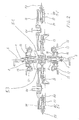
- FIG. 1 shows the upper feed area of a filling and packaging machine for the continuous filling and packaging of containers from a film tube 51.
- the elongated film tube 51 which is rectangular in cross section, can be guided downwards in the vertical direction, as indicated by arrow 52.
- a plurality of equally spaced guide parts 2 are provided, which can be guided on longitudinally opposite sides of the film tube 51 at the same speed as the latter.
- several equally spaced, arranged between the guide parts 2 and movable therewith, convex in the direction of the film tube 51 formed pressure parts 1 are provided.
- Each guide part 2 has an internal guide running perpendicular to the film tube 51, in which a pin 9 is mounted so as to be longitudinally displaceable, which has a roller 10 rolling on a cam track 12 fixed to the frame at its end facing away from the film tube 51 and a parallel to the end facing the film tube 51 has dosing surface 13.
- a compression spring 11 is provided which surrounds the pin 9 and which is supported on the one hand on a stop of the guide part 2 and on the other hand on a stop of the pin 9. The bolt is therefore under pressure. This ensures that the roller 10 is always in contact with the cam track 12.
- the distance between the metering surface 13 and the central axis is determined at the same time.
- Each pressure part has an end face 54 facing the film tube and adjoining side surfaces 55.
- the side surfaces 55 of the pressure parts 1 are flat; they run away from the end face 54 at an obtuse angle.
- each pressure part 1 has an inner guide running perpendicular to the film tube 51, in which a bolt 3 is mounted so as to be longitudinally displaceable, which has a roller 4 rolling on a cam track 6 fixed to the frame at its end facing away from the film tube 51 and parallel to its end facing the film tube 51 this has extending end face 54.
- a compression spring 5 which surrounds the bolt 3 is provided in the inner guide and is supported on the one hand on a stop of the pressure part 1 and on the other hand on a stop of the bolt 3. The bolt 3 and its roller 4 is therefore under pressure and is therefore always in contact with the cam track 6.
- the cam track 6 is adjustable in height. Bolts protrude from the cam track 6, which engage in elongated holes 7, which are provided in tabs fixed to the housing. The cam track 6 is thus screwed to the frame via the bolts and the elongated holes 7.
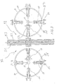
- Figure 3 shows the molding station of the machine. This station is arranged above the feed area of the machine shown in FIG. 1.
- the representation of FIG. 3 lies in a plane that runs perpendicular to the plane of the drawing in FIG. 1.
- a cylinder is arranged on both sides of the film tube 51 which is guided downward in the direction of the arrow 53.
- Each cylinder is rotatably supported about an axis 17.
- the axes 17 run at the same distance opposite one another from the central axis 53 of the film tube 51
- the molded parts 23 are attached to the peripheral surfaces of the cylinders 18.
- the rotational speeds of the cylinders 18, indicated by the arrows 56, are opposite and of the same size.
- the molded parts 23 run in a vertical direction perpendicular to the plane of the guide parts 2 and pressure parts 1 Level. They have two mandrel-shaped elevations 23 facing the film tube 51 in the longitudinal direction of the film tube 51.
- the molded parts 23 are arranged at the same distance from one another on the circumferential surface of each cylinder 18.
- a pin 58 is mounted in a longitudinally displaceable manner, which has on its end facing away from the film tube 51 a roller 20 rolling on a cam track 19 fixed to the frame and on its end facing the film tube 51 the thorn-shaped elevations 23 facing it owns.
- a compression spring 21 which surrounds the pin 58 and which is supported on the one hand on a stop of the guide 57 and on the other hand on a stop of the pin 58.
- the bolt 58 is thus spring-loaded so that it is always in contact with the cam guide 19.
- the cam track 19 has an elevation 59 in the area in which the mandrel-shaped elevations 23 engage with the film tube 51.
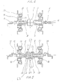
- the film tube 51 runs in the middle of the illustration.
- the cylinders 18 shown in FIG. 3 are shown on the left and right poses. These are rotatably supported about shafts 24.
- the same parts are provided with the same reference numbers, so that they do not have to be described again.
- the pressure pieces 1 are shown in section above and below the film tube 51.
- Fig. 4 shows the pressure pieces 1 in an enlarged view from above.
- Fig. 5 shows the guide pieces, also in an enlarged view from above.
- Each guide piece has a U-shaped part 61 facing the film tube 51 with a base surface 62 which can be brought into contact with a surface of the film tube 51 and two side surfaces 63 projecting at right angles and enclosing the film tube 51.
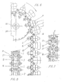
- FIG. 6 shows a chain with pressure parts 1 and guide parts 2 arranged thereon.
- the chain is guided over an upper sprocket 25 which is rotatably mounted about a horizontal axis 26 arranged at a distance from the film tube.
- 7 and 8 show the chain from the inside and outside.
- the guide parts and pressure parts are also arranged on two chains.
- the chains run in a vertical plane on both sides of the film tube 29 and symmetrically to this.
- Each chain is guided over an upper sprocket 25 and over a lower sprocket 28.
- the upper chain wheels 25 are rotatably mounted about a respective horizontal axis 26 which is arranged at a distance from the film tube 29.
- the lower sprockets 28 are rotatably mounted about a respective horizontal axis 27 which is arranged at a distance from the film tube 29.
- the mutually facing engagement areas of the chains are designated by 15.
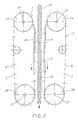
- FIG. 9 The operation of the machine is shown schematically in FIG. 9.
- the film tube 29 moves from top to bottom in FIG. 9. Due to the engagement of the pressure parts 1, opposing walls of the film tube are pressed against one another and then welded. The actual container regions 30 lie between these regions.
- the film tube therefore leaves the machine as a chain of connected packaging containers.
- the packaging container chain then consists of equally spaced container areas 30 and connecting areas connecting them.
- the liquid level is higher than the first engagement area of the pressure pieces in the direction of movement of the film tube 51.
- This first engagement area is denoted by 71 in FIG. 1.
- the liquid level is above this range approximately at the level designated 72. This ensures that air is never trapped in the containers.
- the metering takes place via the metering surfaces 13 of the guide pieces 2.
Landscapes
- Engineering & Computer Science (AREA)
- Mechanical Engineering (AREA)
- Containers And Plastic Fillers For Packaging (AREA)
- Supplying Of Containers To The Packaging Station (AREA)
- Basic Packing Technique (AREA)
- Fish Paste Products (AREA)
- Formation And Processing Of Food Products (AREA)
Priority Applications (1)
| Application Number | Priority Date | Filing Date | Title |
|---|---|---|---|
| AT89114766T ATE98177T1 (de) | 1989-06-06 | 1989-08-09 | Abfuell- und verpackungsmaschine. |
Applications Claiming Priority (2)
| Application Number | Priority Date | Filing Date | Title |
|---|---|---|---|
| IT8904837A IT1233620B (it) | 1989-06-06 | 1989-06-06 | Macchina di riempimento e confezionamento |
| IT483789 | 1989-06-06 |
Publications (2)
| Publication Number | Publication Date |
|---|---|
| EP0401422A1 true EP0401422A1 (fr) | 1990-12-12 |
| EP0401422B1 EP0401422B1 (fr) | 1993-12-08 |
Family
ID=11114726
Family Applications (1)
| Application Number | Title | Priority Date | Filing Date |
|---|---|---|---|
| EP89114766A Expired - Lifetime EP0401422B1 (fr) | 1989-06-06 | 1989-08-09 | Machine de remplissage et d'emballage |
Country Status (9)
| Country | Link |
|---|---|
| US (1) | US5001891A (fr) |
| EP (1) | EP0401422B1 (fr) |
| AT (1) | ATE98177T1 (fr) |
| CA (1) | CA1311185C (fr) |
| DE (1) | DE58906382D1 (fr) |
| DK (1) | DK172379B1 (fr) |
| ES (1) | ES2046400T3 (fr) |
| IT (1) | IT1233620B (fr) |
| NO (1) | NO300885B1 (fr) |
Cited By (2)
| Publication number | Priority date | Publication date | Assignee | Title |
|---|---|---|---|---|
| WO2000044624A1 (fr) * | 1999-01-27 | 2000-08-03 | Tetra Laval Holdings & Finance Sa | Disposition des machoires de scellement d'un materiau d'emballage en tube continu |
| EP3053834A1 (fr) * | 2015-02-04 | 2016-08-10 | Tetra Laval Holdings & Finance S.A. | Ensemble de formage et procédé de formage d'une pluralité de paquets scellés pour produits alimentaires versables à partir d'un tube de matériau d'emballage |
Families Citing this family (31)
| Publication number | Priority date | Publication date | Assignee | Title |
|---|---|---|---|---|
| US5537802A (en) * | 1994-11-29 | 1996-07-23 | The Procter & Gamble Company | Packaging apparatus and method for preventing separation of package seals |
| IT1280811B1 (it) * | 1995-03-21 | 1998-02-11 | Hitech Systems Srl | Dispositivo per la termosigillatura in continuo di involucri di confezionamento di materiale polimerico termosaldabile e macchine |
| JP3827777B2 (ja) * | 1996-09-17 | 2006-09-27 | 四国化工機株式会社 | 包装容器成形フラップ |
| US5752370A (en) * | 1996-11-13 | 1998-05-19 | Triangle Package Machinery Company | Continuous motion drive for form, fill and seal machine |
| US5852920A (en) * | 1996-11-13 | 1998-12-29 | Triangle Package Machinery Company | Longitudinal seam sealer for continuous motion form, fill and seal machine |
| DE69724598T2 (de) * | 1997-06-27 | 2004-08-05 | Tetra Laval Holdings & Finance S.A. | Verpackungsmaschine zum kontinuierlichen Herstellen von versiegelten Verpackungen fliessfähiger Nahrungsmittel aus schlauchförmigem Verpackungsmaterial |
| ATE252486T1 (de) * | 1997-06-27 | 2003-11-15 | Tetra Laval Holdings & Finance | Verpackungsmaschine zum kontinuierlichen herstellen von versiegelten verpackungen fliessfähiger nahrungsmittel aus schlauchförmigem verpackungsmaterial |
| EP0887263B1 (fr) * | 1997-06-27 | 2004-11-17 | Tetra Laval Holdings & Finance SA | Machine d'emballage pour produire en continu des emballages scellés contenant un produit alimentaire sous forme liquide, dans un matériau d'emballage tubulaire |
| ATE228083T1 (de) * | 1997-06-27 | 2002-12-15 | Tetra Laval Holdings & Finance | Verpackungsmaschine zum kontinuierlichen herstellen von versiegelten verpackungen fliessfähiger nahrungsmittel aus schlauchförmigem verpackungsmaterial |
| DE69725711T2 (de) * | 1997-06-27 | 2004-06-17 | Tetra Laval Holdings & Finance S.A. | Verpackungsmaschine zum kontinuierlichen Herstellen von versiegelten Verpackungen fliessfähiger Nahrungsmittel aus schlauchförmigem Verpackungsmaterial |
| DK0887269T3 (da) * | 1997-06-27 | 2004-02-16 | Tetra Laval Holdings & Finance | Emballeringsenhed til kontinuerlig fremstilling af forseglede emballager, der indeholder hældbare fødevarer, og en fremgangsmåde til overvågning af en forseglingsfunktion udført på emballeringsenheden |
| US6016953A (en) * | 1997-08-14 | 2000-01-25 | Tetra Laval Holdings & Finance, Sa | Tetrahedral top carton |
| EP0945349B1 (fr) * | 1998-03-27 | 2004-01-02 | SIG Pack Systems AG | Dispositif de soudage et de coupe transversal d'un tube en matière thermoplastique, spécialement pour machines de fabrication de sacs tubulaires |
| US6038839A (en) | 1998-11-06 | 2000-03-21 | Triangle Package Machinery Company | Longitudinal seam sealer for polyethylene material |
| US6876896B1 (en) | 1999-04-26 | 2005-04-05 | Ab Tetrapak | Variable motion system and method |
| WO2000073045A1 (fr) * | 1999-06-01 | 2000-12-07 | Roll-O-Matic A/S | Unite de soudage |
| PT1101700E (pt) * | 1999-11-18 | 2004-08-31 | Tetra Laval Holdings & Finance | Unidade de formacao e vedacao para maquina de embalar produtos alimentares escoaveis |
| US6928794B2 (en) * | 2003-08-01 | 2005-08-16 | 3M Innovative Properties Company | Method and apparatus for making a continuous series of filled pouches |
| ES2269967T3 (es) * | 2003-10-22 | 2007-04-01 | TETRA LAVAL HOLDINGS & FINANCE SA | Unidad para formar y sellar para una maquina para envasar productos alimentarios vertibles. |
| NL1025987C2 (nl) * | 2004-04-20 | 2005-10-24 | Robert Bosch Verpakkingsmachin | Inrichting, samenstel en werkwijze voor het vervaardigen van zakken alsmede een dergelijke zak. |
| US20080066430A1 (en) * | 2006-09-15 | 2008-03-20 | Triangle Package Machinery Company | Continuous motion drive mechanism for a form, fill, and seal machine |
| JP2009091021A (ja) * | 2007-10-10 | 2009-04-30 | Ishida Co Ltd | 製袋包装機 |
| US8539741B2 (en) * | 2010-02-10 | 2013-09-24 | Triangle Package Machinery Company | Seal and cut method and apparatus |
| EP2923959B1 (fr) * | 2014-03-25 | 2016-11-16 | Tetra Laval Holdings & Finance S.A. | Unité de pliage pour la production d'emballages de produits alimentaires pouvant être versés dans un tuyau de matériau d'emballage à partir d'emballages scellés |
| EP3053835B1 (fr) | 2015-02-04 | 2019-04-03 | Tetra Laval Holdings & Finance S.A. | Ensemble de formage et procédé de formage d'une pluralité de paquets scellés pour produits alimentaires versables à partir d'un tube de matériau d'emballage |
| US10358244B2 (en) | 2015-10-26 | 2019-07-23 | Triangle Package Machinery Co. | Rotatable sealing jaw assembly for a form, fill and seal machine |
| EP3476751B1 (fr) * | 2017-10-31 | 2020-04-22 | Tetra Laval Holdings & Finance S.A. | Ensemble d'emballage destiné à former et sceller une pluralité de paquets contenant un produit alimentaire versable |
| WO2021001144A1 (fr) * | 2019-07-01 | 2021-01-07 | Tetra Laval Holdings & Finance S.A. | Ensemble emballage pour former et sceller une pluralité de paquets contenant un produit versable et procédé pour former et sceller une pluralité de paquets |
| WO2022017745A1 (fr) * | 2020-07-23 | 2022-01-27 | Tetra Laval Holdings & Finance S.A. | Unité de mise en forme d'emballages, appareil d'emballage ayant une unité de mise en forme d'emballages, et procédé de mise en forme d'emballages |
| JP2024530581A (ja) * | 2021-08-05 | 2024-08-23 | テトラ ラバル ホールディングス アンド ファイナンス エス エイ | リニアモータシステム、対応する成形アセンブリ及び方法 |
| IT202300011751A1 (it) * | 2023-06-08 | 2024-12-08 | Tetra Laval Holdings & Finance | Apparato di formazione di pacchetti e macchina di confezionamento per formare pacchetti |
Citations (6)
| Publication number | Priority date | Publication date | Assignee | Title |
|---|---|---|---|---|
| CA412685A (fr) * | 1943-05-25 | T. Troy Constantine | Appareil a classer le cuir | |
| US3006121A (en) * | 1959-07-29 | 1961-10-31 | Omori Takeo | Means for making paper containers and filling them with fluent material |
| DE1213781B (de) * | 1963-01-16 | 1966-03-31 | Tetra Pak Ab | Verfahren und Vorrichtung zum Herstellen gefuellter und verschlossener quaderfoermiger Packungen |
| US3426499A (en) * | 1965-02-18 | 1969-02-11 | Richard E Paige | Method of packaging food articles |
| US4074504A (en) * | 1975-04-28 | 1978-02-21 | The Dow Chemical Company | Method of forming filling and sealing an industrial size bag |
| US4442656A (en) * | 1981-10-26 | 1984-04-17 | Universal Packaging, Inc. | Filling and sealing machine for providing a flat bottom package |
Family Cites Families (5)
| Publication number | Priority date | Publication date | Assignee | Title |
|---|---|---|---|---|
| US2738631A (en) * | 1950-12-30 | 1956-03-20 | Hermorion Ltd | Apparatus for continuously producing packages from a tube or sleeve |
| US3320718A (en) * | 1964-06-01 | 1967-05-23 | Holstein & Kappert Maschf | Apparatus for filling and sealing containers |
| DE2810896A1 (de) * | 1978-03-13 | 1979-09-27 | Windmoeller & Hoelscher | Verfahren und vorrichtung zum herstellen von beuteln aus schlauch- oder halbschlauchbahnen |
| GB2162460B (en) * | 1984-07-31 | 1987-07-22 | Shibuya Kogyo Co Ltd | Apparatus for transversely sealing packages |
| IT8504840A0 (it) * | 1985-08-13 | 1985-08-13 | Branchi Franca | Procedimento per confezionare da un tubo continuo di materiale flessibile, mantenuto pieno di sostanze fluide, dei contenitori di forma prismatica senza orecchiette laterali, con estremita' a falde spianabili |
-
1989
- 1989-06-06 IT IT8904837A patent/IT1233620B/it active
- 1989-08-09 ES ES198989114766T patent/ES2046400T3/es not_active Expired - Lifetime
- 1989-08-09 AT AT89114766T patent/ATE98177T1/de not_active IP Right Cessation
- 1989-08-09 DE DE89114766T patent/DE58906382D1/de not_active Expired - Fee Related
- 1989-08-09 EP EP89114766A patent/EP0401422B1/fr not_active Expired - Lifetime
- 1989-09-04 NO NO893543A patent/NO300885B1/no not_active IP Right Cessation
- 1989-09-15 US US07/407,960 patent/US5001891A/en not_active Expired - Lifetime
- 1989-09-26 CA CA000613130A patent/CA1311185C/fr not_active Expired - Lifetime
- 1989-10-20 DK DK522289A patent/DK172379B1/da not_active IP Right Cessation
Patent Citations (6)
| Publication number | Priority date | Publication date | Assignee | Title |
|---|---|---|---|---|
| CA412685A (fr) * | 1943-05-25 | T. Troy Constantine | Appareil a classer le cuir | |
| US3006121A (en) * | 1959-07-29 | 1961-10-31 | Omori Takeo | Means for making paper containers and filling them with fluent material |
| DE1213781B (de) * | 1963-01-16 | 1966-03-31 | Tetra Pak Ab | Verfahren und Vorrichtung zum Herstellen gefuellter und verschlossener quaderfoermiger Packungen |
| US3426499A (en) * | 1965-02-18 | 1969-02-11 | Richard E Paige | Method of packaging food articles |
| US4074504A (en) * | 1975-04-28 | 1978-02-21 | The Dow Chemical Company | Method of forming filling and sealing an industrial size bag |
| US4442656A (en) * | 1981-10-26 | 1984-04-17 | Universal Packaging, Inc. | Filling and sealing machine for providing a flat bottom package |
Cited By (4)
| Publication number | Priority date | Publication date | Assignee | Title |
|---|---|---|---|---|
| WO2000044624A1 (fr) * | 1999-01-27 | 2000-08-03 | Tetra Laval Holdings & Finance Sa | Disposition des machoires de scellement d'un materiau d'emballage en tube continu |
| EP3053834A1 (fr) * | 2015-02-04 | 2016-08-10 | Tetra Laval Holdings & Finance S.A. | Ensemble de formage et procédé de formage d'une pluralité de paquets scellés pour produits alimentaires versables à partir d'un tube de matériau d'emballage |
| WO2016124559A1 (fr) * | 2015-02-04 | 2016-08-11 | Tetra Laval Holdings & Finance S.A. | Ensemble de formage et procédé de formage d'une pluralité de paquets scellés pour produits alimentaires liquides à partir d'un tube de matériau d'emballage |
| US10449728B2 (en) | 2015-02-04 | 2019-10-22 | Tetra Laval Holdings & Finance S.A. | Forming assembly and method for forming a plurality of sealed packs for pourable food products starting from a tube of packaging material |
Also Published As
| Publication number | Publication date |
|---|---|
| US5001891A (en) | 1991-03-26 |
| CA1311185C (fr) | 1992-12-08 |
| DE58906382D1 (de) | 1994-01-20 |
| DK522289D0 (da) | 1989-10-20 |
| NO893543L (no) | 1990-12-07 |
| IT1233620B (it) | 1992-04-07 |
| ES2046400T3 (es) | 1994-02-01 |
| ATE98177T1 (de) | 1993-12-15 |
| NO300885B1 (no) | 1997-08-11 |
| IT8904837A0 (it) | 1989-06-06 |
| DK522289A (da) | 1990-12-07 |
| NO893543D0 (no) | 1989-09-04 |
| EP0401422B1 (fr) | 1993-12-08 |
| DK172379B1 (da) | 1998-05-04 |
Similar Documents
| Publication | Publication Date | Title |
|---|---|---|
| EP0401422B1 (fr) | Machine de remplissage et d'emballage | |
| EP0368095B1 (fr) | Machine pour la fabrication et le remplissage de sachets tubulaires | |
| DE2751928A1 (de) | Vorrichtung zur herstellung von zumindest etwa quaderfoermigen verpackungsbehaeltern | |
| DE69717260T2 (de) | Verpackungsmaschine zum kontinuierlichen Herstellen von versiegelten Verpackungen fliessfähiger Nahrungsmittel aus schlauchförmigem Verpackungsmaterial | |
| DE69107343T2 (de) | Vorrichtung zum Formen quaderförmiger Beutelpackungen. | |
| DE69917039T2 (de) | Form- und Siegeleinheit für eine Maschine zum Verpacken von flüssigen Nahrungsmitteln | |
| CH427622A (de) | Verfahren und Vorrichtung zur Herstellung von mit fliessfähigem Füllgut gefüllten Quaderpackungen | |
| EP0086364A2 (fr) | Appareil pour sceller un emballage de fluides | |
| DE2404826A1 (de) | Vorrichtung zum formen von packungen | |
| DE2942117A1 (de) | Vorrichtung zum ausformen von fluessigkeitspackungen | |
| EP0093409B1 (fr) | Dispositif pour le transport stabile et synchrone d'emballages pour produits fluides dans des postes de traitement | |
| DE4015803C1 (en) | Link element for energy transfer chain - has height of cross-plate relative energy lines adjustable for compression of resilient packing elements and secure energy lines retention | |
| DE69709513T2 (de) | Klappenvorrichtung zum Formen einer Schlauchpackung | |
| DE68902736T2 (de) | Apparat zum verschliessen einer verpackung um einen zu verpackenden artikel. | |
| EP0044395B1 (fr) | Dispositif pour fabriquer continuellement des emballages remplis de forme prismatique | |
| DE3301451A1 (de) | Steuervorrichtung fuer eine kartonversiegel- und/oder -verschliessmaschine | |
| DE2213940C3 (de) | Vorrichtung zum Prüfen der Festigkeit von zerbrechbaren Gegenständen, insbesondere von Glasflaschen | |
| DE2355921C3 (de) | Materialbahn-Fördereinrichtung | |
| DE3639472C2 (fr) | ||
| DE2421539B2 (de) | Vorrichtung zum Einwickeln quaderförmiger Gegenstande | |
| DE2544024A1 (de) | Maschine zum herstellen von mit fluessigkeit gefuellten beutelpackungen und zum umformen derselben in quaderform | |
| EP0764509B1 (fr) | Dispositif de fermeture de moule sans colonnes | |
| DE3433802A1 (de) | Vorrichtung zum formen, verschweissen und foerdern von verpackungen | |
| CH658435A5 (de) | Vorrichtung zum abfuellen und verdichten von gut in beuteln. | |
| DE3442943A1 (de) | Vorrichtung zum falten der oeffnung von gefuellten saecken |
Legal Events
| Date | Code | Title | Description |
|---|---|---|---|
| PUAI | Public reference made under article 153(3) epc to a published international application that has entered the european phase |
Free format text: ORIGINAL CODE: 0009012 |
|
| AK | Designated contracting states |
Kind code of ref document: A1 Designated state(s): AT BE CH DE ES FR GB GR IT LI LU NL SE |
|
| 17P | Request for examination filed |
Effective date: 19901116 |
|
| 17Q | First examination report despatched |
Effective date: 19920724 |
|
| GRAA | (expected) grant |
Free format text: ORIGINAL CODE: 0009210 |
|
| AK | Designated contracting states |
Kind code of ref document: B1 Designated state(s): AT BE CH DE ES FR GB GR IT LI LU NL SE |
|
| PG25 | Lapsed in a contracting state [announced via postgrant information from national office to epo] |
Ref country code: IT Free format text: LAPSE BECAUSE OF FAILURE TO SUBMIT A TRANSLATION OF THE DESCRIPTION OR TO PAY THE FEE WITHIN THE PRE;WARNING: LAPSES OF ITALIAN PATENTS WITH EFFECTIVE DATE BEFORE 2007 MAY HAVE OCCURRED AT ANY TIME BEFORE 2007. THE CORRECT EFFECTIVE DATE MAY BE DIFFERENT FROM THE ONE RECORDED.SCRIBED TIME-LIMIT Effective date: 19931208 Ref country code: GR Free format text: LAPSE BECAUSE OF FAILURE TO SUBMIT A TRANSLATION OF THE DESCRIPTION OR TO PAY THE FEE WITHIN THE PRESCRIBED TIME-LIMIT Effective date: 19931208 Ref country code: BE Effective date: 19931208 |
|
| REF | Corresponds to: |
Ref document number: 98177 Country of ref document: AT Date of ref document: 19931215 Kind code of ref document: T |
|
| GBT | Gb: translation of ep patent filed (gb section 77(6)(a)/1977) |
Effective date: 19931216 |
|
| REF | Corresponds to: |
Ref document number: 58906382 Country of ref document: DE Date of ref document: 19940120 |
|
| REG | Reference to a national code |
Ref country code: ES Ref legal event code: FG2A Ref document number: 2046400 Country of ref document: ES Kind code of ref document: T3 |
|
| ET | Fr: translation filed | ||
| PG25 | Lapsed in a contracting state [announced via postgrant information from national office to epo] |
Ref country code: AT Effective date: 19940809 |
|
| PG25 | Lapsed in a contracting state [announced via postgrant information from national office to epo] |
Ref country code: LU Free format text: LAPSE BECAUSE OF NON-PAYMENT OF DUE FEES Effective date: 19940831 |
|
| PLBE | No opposition filed within time limit |
Free format text: ORIGINAL CODE: 0009261 |
|
| STAA | Information on the status of an ep patent application or granted ep patent |
Free format text: STATUS: NO OPPOSITION FILED WITHIN TIME LIMIT |
|
| 26N | No opposition filed | ||
| EAL | Se: european patent in force in sweden |
Ref document number: 89114766.2 |
|
| REG | Reference to a national code |
Ref country code: GB Ref legal event code: IF02 |
|
| PGFP | Annual fee paid to national office [announced via postgrant information from national office to epo] |
Ref country code: FR Payment date: 20030814 Year of fee payment: 15 |
|
| PGFP | Annual fee paid to national office [announced via postgrant information from national office to epo] |
Ref country code: NL Payment date: 20030819 Year of fee payment: 15 |
|
| PGFP | Annual fee paid to national office [announced via postgrant information from national office to epo] |
Ref country code: SE Payment date: 20030820 Year of fee payment: 15 |
|
| PGFP | Annual fee paid to national office [announced via postgrant information from national office to epo] |
Ref country code: DE Payment date: 20030828 Year of fee payment: 15 Ref country code: CH Payment date: 20030828 Year of fee payment: 15 |
|
| PGFP | Annual fee paid to national office [announced via postgrant information from national office to epo] |
Ref country code: GB Payment date: 20040726 Year of fee payment: 16 |
|
| PGFP | Annual fee paid to national office [announced via postgrant information from national office to epo] |
Ref country code: ES Payment date: 20040806 Year of fee payment: 16 |
|
| PG25 | Lapsed in a contracting state [announced via postgrant information from national office to epo] |
Ref country code: SE Free format text: LAPSE BECAUSE OF NON-PAYMENT OF DUE FEES Effective date: 20040810 |
|
| PG25 | Lapsed in a contracting state [announced via postgrant information from national office to epo] |
Ref country code: CH Free format text: LAPSE BECAUSE OF NON-PAYMENT OF DUE FEES Effective date: 20040831 Ref country code: LI Free format text: LAPSE BECAUSE OF NON-PAYMENT OF DUE FEES Effective date: 20040831 |
|
| PG25 | Lapsed in a contracting state [announced via postgrant information from national office to epo] |
Ref country code: DE Free format text: LAPSE BECAUSE OF NON-PAYMENT OF DUE FEES Effective date: 20050301 Ref country code: NL Free format text: LAPSE BECAUSE OF NON-PAYMENT OF DUE FEES Effective date: 20050301 |
|
| EUG | Se: european patent has lapsed | ||
| REG | Reference to a national code |
Ref country code: CH Ref legal event code: PL |
|
| PG25 | Lapsed in a contracting state [announced via postgrant information from national office to epo] |
Ref country code: FR Free format text: LAPSE BECAUSE OF NON-PAYMENT OF DUE FEES Effective date: 20050429 |
|
| NLV4 | Nl: lapsed or anulled due to non-payment of the annual fee |
Effective date: 20050301 |
|
| REG | Reference to a national code |
Ref country code: FR Ref legal event code: ST |
|
| PG25 | Lapsed in a contracting state [announced via postgrant information from national office to epo] |
Ref country code: GB Free format text: LAPSE BECAUSE OF NON-PAYMENT OF DUE FEES Effective date: 20050809 |
|
| PG25 | Lapsed in a contracting state [announced via postgrant information from national office to epo] |
Ref country code: ES Free format text: LAPSE BECAUSE OF NON-PAYMENT OF DUE FEES Effective date: 20050810 |
|
| GBPC | Gb: european patent ceased through non-payment of renewal fee |
Effective date: 20050809 |
|
| REG | Reference to a national code |
Ref country code: ES Ref legal event code: FD2A Effective date: 20050810 |