EP0401529A1 - Chambre de combustion d'une turbine à gaz - Google Patents
Chambre de combustion d'une turbine à gaz Download PDFInfo
- Publication number
- EP0401529A1 EP0401529A1 EP90108684A EP90108684A EP0401529A1 EP 0401529 A1 EP0401529 A1 EP 0401529A1 EP 90108684 A EP90108684 A EP 90108684A EP 90108684 A EP90108684 A EP 90108684A EP 0401529 A1 EP0401529 A1 EP 0401529A1
- Authority
- EP
- European Patent Office
- Prior art keywords
- combustion chamber
- burners
- burner
- premix burners
- air
- Prior art date
- Legal status (The legal status is an assumption and is not a legal conclusion. Google has not performed a legal analysis and makes no representation as to the accuracy of the status listed.)
- Granted
Links
Images



Classifications
-
- F—MECHANICAL ENGINEERING; LIGHTING; HEATING; WEAPONS; BLASTING
- F23—COMBUSTION APPARATUS; COMBUSTION PROCESSES
- F23R—GENERATING COMBUSTION PRODUCTS OF HIGH PRESSURE OR HIGH VELOCITY, e.g. GAS-TURBINE COMBUSTION CHAMBERS
- F23R3/00—Continuous combustion chambers using liquid or gaseous fuel
- F23R3/28—Continuous combustion chambers using liquid or gaseous fuel characterised by the fuel supply
- F23R3/30—Continuous combustion chambers using liquid or gaseous fuel characterised by the fuel supply comprising fuel prevapourising devices
-
- F—MECHANICAL ENGINEERING; LIGHTING; HEATING; WEAPONS; BLASTING
- F23—COMBUSTION APPARATUS; COMBUSTION PROCESSES
- F23D—BURNERS
- F23D11/00—Burners using a direct spraying action of liquid droplets or vaporised liquid into the combustion space
- F23D11/36—Details
- F23D11/40—Mixing tubes; Burner heads
- F23D11/402—Mixing chambers downstream of the nozzle
-
- F—MECHANICAL ENGINEERING; LIGHTING; HEATING; WEAPONS; BLASTING
- F23—COMBUSTION APPARATUS; COMBUSTION PROCESSES
- F23D—BURNERS
- F23D17/00—Burners for combustion simultaneously or alternately of gaseous or liquid or pulverulent fuel
- F23D17/002—Burners for combustion simultaneously or alternately of gaseous or liquid or pulverulent fuel gaseous or liquid fuel
-
- F—MECHANICAL ENGINEERING; LIGHTING; HEATING; WEAPONS; BLASTING
- F23—COMBUSTION APPARATUS; COMBUSTION PROCESSES
- F23R—GENERATING COMBUSTION PRODUCTS OF HIGH PRESSURE OR HIGH VELOCITY, e.g. GAS-TURBINE COMBUSTION CHAMBERS
- F23R3/00—Continuous combustion chambers using liquid or gaseous fuel
- F23R3/02—Continuous combustion chambers using liquid or gaseous fuel characterised by the air-flow or gas-flow configuration
- F23R3/04—Air inlet arrangements
- F23R3/10—Air inlet arrangements for primary air
-
- F—MECHANICAL ENGINEERING; LIGHTING; HEATING; WEAPONS; BLASTING
- F23—COMBUSTION APPARATUS; COMBUSTION PROCESSES
- F23R—GENERATING COMBUSTION PRODUCTS OF HIGH PRESSURE OR HIGH VELOCITY, e.g. GAS-TURBINE COMBUSTION CHAMBERS
- F23R3/00—Continuous combustion chambers using liquid or gaseous fuel
- F23R3/02—Continuous combustion chambers using liquid or gaseous fuel characterised by the air-flow or gas-flow configuration
- F23R3/04—Air inlet arrangements
- F23R3/10—Air inlet arrangements for primary air
- F23R3/12—Air inlet arrangements for primary air inducing a vortex
-
- F—MECHANICAL ENGINEERING; LIGHTING; HEATING; WEAPONS; BLASTING
- F23—COMBUSTION APPARATUS; COMBUSTION PROCESSES
- F23R—GENERATING COMBUSTION PRODUCTS OF HIGH PRESSURE OR HIGH VELOCITY, e.g. GAS-TURBINE COMBUSTION CHAMBERS
- F23R3/00—Continuous combustion chambers using liquid or gaseous fuel
- F23R3/28—Continuous combustion chambers using liquid or gaseous fuel characterised by the fuel supply
- F23R3/34—Feeding into different combustion zones
-
- F—MECHANICAL ENGINEERING; LIGHTING; HEATING; WEAPONS; BLASTING
- F23—COMBUSTION APPARATUS; COMBUSTION PROCESSES
- F23R—GENERATING COMBUSTION PRODUCTS OF HIGH PRESSURE OR HIGH VELOCITY, e.g. GAS-TURBINE COMBUSTION CHAMBERS
- F23R3/00—Continuous combustion chambers using liquid or gaseous fuel
- F23R3/42—Continuous combustion chambers using liquid or gaseous fuel characterised by the arrangement or form of the flame tubes or combustion chambers
- F23R3/50—Combustion chambers comprising an annular flame tube within an annular casing
-
- F—MECHANICAL ENGINEERING; LIGHTING; HEATING; WEAPONS; BLASTING
- F23—COMBUSTION APPARATUS; COMBUSTION PROCESSES
- F23C—METHODS OR APPARATUS FOR COMBUSTION USING FLUID FUEL OR SOLID FUEL SUSPENDED IN A CARRIER GAS OR AIR
- F23C2900/00—Special features of, or arrangements for combustion apparatus using fluid fuels or solid fuels suspended in air; Combustion processes therefor
- F23C2900/07002—Premix burners with air inlet slots obtained between offset curved wall surfaces, e.g. double cone burners
Definitions
- the present invention relates to a combustion chamber according to the preamble of claim 1.
- premix burners With regard to the prescribed, extremely low NO x emissions when operating a gas turbine, many manufacturers are adopting premix burners.
- One of the disadvantages of premix burners is that they extinguish at very low air numbers, depending on the temperature of the compressor of the gas turbine, at around 2. For this reason, such premix burners must be supported by one or more pilot burners in the partial load operation of a gas turbine. Diffusion burners are usually used for this.
- This technology enables very low No x emissions in the area of full load. In contrast, this auxiliary burner system leads at partial load operation at significantly higher NO x emissions.
- the invention seeks to remedy this.
- the invention as characterized in the claims, is based on the object of providing a combustion chamber which, with minimized exhaust gas emissions, enables a wide operating range, while optimizing the quality factor for the temperature profile at the turbine inlet, in the technical term "pattern factor".
- main burners are related to the small premix burners, hereinafter referred to as pilot burners, with regard to the flow through them
- the pilot burners work as independent premix burners in the entire load range of the combustion chamber, with the air ratio remaining almost constant. Because the pilot burners can now be operated in the entire load range with an ideal mixture (premix burner), the NO x emissions are very low even at partial load. It also shows that, in the interest of "up-prizing" potential for gas turbines with higher turbine inlet temperatures, the proportion of air that cannot be formed by the burners (lean blowoff limit, CO / UHC) is not, because of the pattern factor, should only be used for cooling purposes.
- a certain proportion of air is introduced via the air nozzles provided here, preferably after the primary combustion zone of the combustion chamber, and there it is ensured that perfect mixing takes place.
- This has the advantage that the proportion of air that ensures “up-rating” and is therefore blown directly into the secondary combustion zone prevents the undesirable "thinning" of the primary zone. Since the air nozzles are located at a point with a very low air velocity and only occupy a limited width of the front wall, their influence on the main flow field in the primary area is only very weak. In particular, the air nozzles do not interfere with the cross-ignition between primary burners and main burners. Another advantage of these air nozzles results from their position on the front wall; this zone would become very hot there without the cooling effect of the air jets.
- main burners and the pilot burners consist of so-called double-cone burners of different sizes, and if these are integrated in an annular combustion chamber. Because the circulating streamlines in the annular combustion chamber come very close to the vortex centers of the pilot burners in such a constellation, ignition is only possible with these pilot burners.
- the amount of fuel that is supplied via the pilot burner is increased until the pilot burner is activated, i.e. until the full amount of fuel is available.
- the configuration is chosen so that this point corresponds to the load shedding condition of the gas turbine.
- the further increase in output then takes place via the main burner.
- the main burners are also fully controlled at the peak load of the system.
- FIG. 1 shows a section of a sector of the front wall 10. This shows the placement of the individual main burners B and pilot burners C. These are evenly and alternately distributed over the circumference of the annular combustion chamber A.
- the size difference shown between main burners B and pilot burners C is only of a qualitative nature.
- the effective size of the individual burners and their distribution and number on the circumference of the front wall 10 of the annular combustion chamber A, as already explained above, depends on the power and size of the combustion chamber itself.
- the main burners B and pilot burners C which are arranged alternately, open out all at the same height in a uniform annular front wall 10, which forms the entry surface of the annular combustion chamber A.
- a number of air nozzles D are provided, which occupy approximately half the width of the front wall 10 in the radial direction.
- a circulating flow that surrounds the burners B and C is created above and below them.
- the role of the roles is here through the co-rotating burner taken over.
- a vortex center is also created around the respective burner; around the pilot burner C, the vortex centers are small and hot, and inherently unstable. These come to rest between the large, cooler vortex centers originating from the main burners B.
- the air nozzles F act, which decisively improve the stabilization of the two, as has already been appreciated in the foregoing. Even if the main burners B are operated lean, as is the case in part-load operation, a very good burnout with low CO / UHC emissions can be expected.
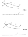
- FIGS. 2 and 3 show a schematic section through an annular combustion chamber A, respectively in the plane of a pilot burner C and. of a main burner B.
- the annular combustion chamber A shown here is tapered in the direction of the turbine inlet D, as can be seen from the central axis E of the annular combustion chamber A shown.
- An individual nozzle 3 is allocated to each burner B, C.
- the burners B, C are at the same time premix burners, that is to say they do without the otherwise usual premix zone.
- these premix burners B, C regardless of their specific design, must be designed in such a way that there is no fear of re-ignition into the premix zone via the respective front panel 10.
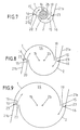
- a premix burner which excellently fulfills this condition is shown comprehensively in FIGS. 6-9 and explained in more detail there, the structure being able to be the same for both burner types (main burner B / pilot burner C), only their size will be different.
- the size ratio between main burner B and pilot burner C is selected such that about 23% of the burner air flows through the pilot burner C and about 77% through the main burner B.
- FIG. 4 and 5 schematically show a main burner B, according to section IV-IV from FIG. 1, and the air nozzles F, according to section V-V from FIG. 1, in a positionally coordinated axial section.
- the structure for the air nozzles F which extends far into the combustion chamber with respect to the front wall 10 and which causes the air to act further downstream of the flame front of the burners B and C must be observed.
- FIGS. 7-9 are used simultaneously with FIG. 6. Furthermore, in order not to make FIG. 6 unnecessarily confusing, the guide plates 21a, 21b shown schematically according to FIGS. 7-9 have only been hinted at in it. In the following, the description of FIG. 6 will optionally refer to the remaining FIGS. 7-9 as required.
- the burner B / C according to FIG. 6, which can be both a pilot burner C and a main burner B in terms of structure, consists of two half-hollow partial cone bodies 1, 2 which are offset from one another.
- the offset of the respective central axis 1b, 2b of the partial cone bodies 1, 2 to each other creates a tangential air inlet slot 19, 20 on both sides in a mirror-image arrangement (FIGS. 7-9), through which the combustion air 15 enters the interior of the burner, ie flows into the cone cavity 14.
- the two partial cone bodies 1, 2 each have a cylindrical initial part 1a, 2a which is also analogous to that Partial cone bodies 1, 2 run offset from one another, so that the tangential air inlet slots 19, 20 are present from the beginning.
- a nozzle 3 is accommodated, the fuel injection 4 of which coincides with the narrowest cross section of the conical cavity 14 formed by the two partial cone bodies 1, 2.
- the size of this nozzle 3 depends on the type of burner, ie whether it is a pilot burner C or main burner B. Of course, the burner can be made purely conical, that is to say without cylindrical starting parts 1a, 2a.
- Both partial cone bodies 1, 2 each have a fuel line 8, 9, which are provided with openings 17 through which the gaseous fuel 13, which is mixed with the combustion air 15 flowing through the tangential air inlet slots 19, 20.
- the position of these fuel lines 8, 9 are provided at the end of the tangential air inlet slots 19, 20, so that the admixture 16 of this fuel 13 with the inflowing combustion air 15 also takes place there.
- the burner B / C has a plate which forms the front wall 10.
- the liquid fuel 12 flowing through the nozzle 3 is injected into the cone cavity 14 at an acute angle such that a cone-shaped fuel spray which is as homogeneous as possible occurs in the burner outlet plane.
- the fuel injector 4 can be an air-assisted nozzle or a pressure atomizer.
- it can also be a dual burner with gaseous and liquid fuel supply, as is described, for example, in EP-A1 210 462.
- the conical liquid fuel profile 5 from the nozzle 3 is enclosed by a rotating combustion air stream 15 flowing in tangentially.
- the concentration of the liquid fuel 12 is continuously reduced in the direction by the mixed-in combustion air 15. If gaseous fuel 13/16 is burned, the mixture is formed with the combustion air 15 directly at the end of the air inlet slots 19, 20.
- the optimal, homogeneous fuel concentration is in the area of the vortex bursting, that is to say in the area of the backflow zone 6 reached the cross section.
- the ignition takes place at the top of the return flow zone 6. Only at this point can a stable flame front 7 arise.
- the nitrogen oxide and carbon monoxide emissions are low if the excess air is at least 60%, which is one of them additional precaution to minimize NO x emissions is available.
- the pollutant emission values are lowest. The same also applies to near-stoichiometric operation when the excess air is replaced by recirculating exhaust gas.
- the design of the burner is particularly suitable for changing the size of the tangential air inlet slots 19, 20 for a given overall length of the burner by fixing the partial cone bodies 1, 2 to the end plate 10 by means of a releasable connection.
- the distance between the two central axes 1b, 2b decreases or increases as a result of radial displacement of the two partial cone bodies 1, 2 to and from one another, and the gap size of the tangential air inlet slots 19, 20 changes accordingly, as is particularly well shown in FIGS. 7-9 emerges.
- the partial cone bodies 1, 2 can also be displaced relative to one another in another plane, as a result of which even an overlap thereof can be controlled.
- 7-9 also shows the position of the guide plates 21a, 21b. They have flow introduction functions, whereby, depending on their length, they extend the respective end of the partial cone bodies 1 and 2 in the flow direction of the combustion air 15.
- the channeling of the combustion air into the cone cavity 14 can be optimized by opening or closing the guide plates 21a, 21b about the pivot point 23, in particular this is necessary if the original gap size of the tangential air inlet slots 19, 20 is changed.
- the burner can also be operated without baffles.
Landscapes
- Engineering & Computer Science (AREA)
- Chemical & Material Sciences (AREA)
- Combustion & Propulsion (AREA)
- Mechanical Engineering (AREA)
- General Engineering & Computer Science (AREA)
- Engine Equipment That Uses Special Cycles (AREA)
- Combustion Methods Of Internal-Combustion Engines (AREA)
- Combustion Of Fluid Fuel (AREA)
Applications Claiming Priority (2)
| Application Number | Priority Date | Filing Date | Title |
|---|---|---|---|
| CH2099/89 | 1989-06-06 | ||
| CH2099/89A CH680084A5 (fr) | 1989-06-06 | 1989-06-06 |
Publications (2)
| Publication Number | Publication Date |
|---|---|
| EP0401529A1 true EP0401529A1 (fr) | 1990-12-12 |
| EP0401529B1 EP0401529B1 (fr) | 1994-06-29 |
Family
ID=4225860
Family Applications (1)
| Application Number | Title | Priority Date | Filing Date |
|---|---|---|---|
| EP90108684A Expired - Lifetime EP0401529B1 (fr) | 1989-06-06 | 1990-05-09 | Chambre de combustion d'une turbine à gaz |
Country Status (10)
| Country | Link |
|---|---|
| US (1) | US5154059A (fr) |
| EP (1) | EP0401529B1 (fr) |
| JP (1) | JP3075732B2 (fr) |
| AT (1) | ATE108011T1 (fr) |
| CH (1) | CH680084A5 (fr) |
| DE (1) | DE59006282D1 (fr) |
| ES (1) | ES2058667T3 (fr) |
| HU (1) | HUT56923A (fr) |
| PL (1) | PL165109B1 (fr) |
| RU (1) | RU2002165C1 (fr) |
Cited By (9)
| Publication number | Priority date | Publication date | Assignee | Title |
|---|---|---|---|---|
| EP0481111A1 (fr) * | 1990-10-17 | 1992-04-22 | Asea Brown Boveri Ag | Chambre de combustion pour turbine à gaz |
| WO1992019915A1 (fr) * | 1991-04-30 | 1992-11-12 | Rolls-Royce Plc | Ensemble chambre de combustion dans un turbo-moteur a combustion |
| FR2683891A1 (fr) * | 1991-11-20 | 1993-05-21 | Snecma | Turbomachine comportant un dispositif pour diminuer l'emission d'oxydes d'azote. |
| US5400587A (en) * | 1991-11-13 | 1995-03-28 | Asea Brown Boveri Ltd. | Gas turbine annular combustion chamber having radially displaced groups of oppositely swirling burners. |
| DE4412315A1 (de) * | 1994-04-11 | 1995-10-12 | Abb Management Ag | Verfahren und Vorrichtung zum Betreiben der Brennkammer einer Gasturbine |
| DE4429539A1 (de) * | 1994-08-19 | 1996-02-22 | Abb Management Ag | Verfahren zur Drehzahlregelung einer Gasturbine bei Lastabwurf |
| DE4429757A1 (de) * | 1994-08-22 | 1996-02-29 | Abb Management Ag | Brennkammer |
| EP0751351A1 (fr) * | 1995-06-26 | 1997-01-02 | Abb Research Ltd. | Chambre de combustion |
| WO2015122797A1 (fr) | 2014-02-12 | 2015-08-20 | Otkrytoe Aktsionernoe Obshchestvo "Gazprom" | Chambre de combustion annulaire dans un moteur à turbine à gaz et son procédé de fonctionnement |
Families Citing this family (21)
| Publication number | Priority date | Publication date | Assignee | Title |
|---|---|---|---|---|
| DE4411624A1 (de) * | 1994-04-02 | 1995-10-05 | Abb Management Ag | Brennkammer mit Vormischbrennern |
| US5479773A (en) * | 1994-10-13 | 1996-01-02 | United Technologies Corporation | Tangential air entry fuel nozzle |
| US5896739A (en) * | 1996-12-20 | 1999-04-27 | United Technologies Corporation | Method of disgorging flames from a two stream tangential entry nozzle |
| US6176087B1 (en) * | 1997-12-15 | 2001-01-23 | United Technologies Corporation | Bluff body premixing fuel injector and method for premixing fuel and air |
| RU2167363C2 (ru) * | 1999-05-25 | 2001-05-20 | Открытое акционерное общество "Авиадвигатель" | Горелка с предварительным смешением газового топлива и воздуха |
| DE19948674B4 (de) * | 1999-10-08 | 2012-04-12 | Alstom | Verbrennungseinrichtung, insbesondere für den Antrieb von Gasturbinen |
| DE10000415A1 (de) * | 2000-01-07 | 2001-09-06 | Alstom Power Schweiz Ag Baden | Verfahren und Vorrichtung zur Unterdrückung von Strömungswirbeln innerhalb einer Strömungskraftmaschine |
| DE10049203A1 (de) * | 2000-10-05 | 2002-05-23 | Alstom Switzerland Ltd | Verfahren zur Brennstoffeinleitung in einen Vormischbrenner |
| US6360776B1 (en) | 2000-11-01 | 2002-03-26 | Rolls-Royce Corporation | Apparatus for premixing in a gas turbine engine |
| DE10205839B4 (de) * | 2002-02-13 | 2011-08-11 | Alstom Technology Ltd. | Vormischbrenner zur Verminderung verbrennungsgetriebener Schwingungen in Verbrennungssystemen |
| DE10219354A1 (de) * | 2002-04-30 | 2003-11-13 | Rolls Royce Deutschland | Gasturbinenbrennkammer mit gezielter Kraftstoffeinbringung zur Verbesserung der Homogenität des Kraftstoff-Luft-Gemisches |
| US6931853B2 (en) * | 2002-11-19 | 2005-08-23 | Siemens Westinghouse Power Corporation | Gas turbine combustor having staged burners with dissimilar mixing passage geometries |
| US7097448B2 (en) * | 2004-05-07 | 2006-08-29 | Peter Chesney | Vortex type gas lamp |
| RU2307985C1 (ru) * | 2006-09-11 | 2007-10-10 | Общество с ограниченной ответственностью "Научно-технический центр "Альтернатива" | Устройство для сжигания топлива |
| DE102007043626A1 (de) | 2007-09-13 | 2009-03-19 | Rolls-Royce Deutschland Ltd & Co Kg | Gasturbinenmagerbrenner mit Kraftstoffdüse mit kontrollierter Kraftstoffinhomogenität |
| US8122725B2 (en) * | 2007-11-01 | 2012-02-28 | General Electric Company | Methods and systems for operating gas turbine engines |
| RU2378576C1 (ru) * | 2008-04-02 | 2010-01-10 | Закрытое акционерное общество "Энергомаш (Холдинг)" | Горелочное устройство камеры сгорания газотурбинной установки |
| FR2950109B1 (fr) * | 2009-09-17 | 2012-07-27 | Turbomeca | Turbomoteur a arbres paralleles |
| USD621873S1 (en) | 2009-07-09 | 2010-08-17 | Science Centre Board | Fire tornado lamp |
| US9170017B2 (en) | 2010-01-06 | 2015-10-27 | The Outdoor Greatroom Company LLLP | Fire container assembly |
| EP2685163B1 (fr) | 2012-07-10 | 2020-03-25 | Ansaldo Energia Switzerland AG | Brûleur de prémélange du type multi-cônes destiné à une turbine à gaz |
Citations (7)
| Publication number | Priority date | Publication date | Assignee | Title |
|---|---|---|---|---|
| FR944310A (fr) * | 1946-01-09 | 1949-04-01 | Bendix Aviat Corp | Brûleurs |
| US3267676A (en) * | 1965-06-23 | 1966-08-23 | Curtiss Wright Corp | Fuel burner structure |
| DE2223093A1 (de) * | 1972-05-12 | 1973-11-22 | Gen Electric | Brenner und brennstoffinjektor |
| US4058977A (en) * | 1974-12-18 | 1977-11-22 | United Technologies Corporation | Low emission combustion chamber |
| GB2043868A (en) * | 1979-03-08 | 1980-10-08 | Rolls Royce | Gas turbine |
| GB2072827A (en) * | 1980-03-29 | 1981-10-07 | Rolls Royce | A tubo-annular combustion chamber |
| EP0210462A1 (fr) * | 1985-07-30 | 1987-02-04 | BBC Brown Boveri AG | Chambre de combustion double |
Family Cites Families (4)
| Publication number | Priority date | Publication date | Assignee | Title |
|---|---|---|---|---|
| US3512359A (en) * | 1968-05-24 | 1970-05-19 | Gen Electric | Dummy swirl cup combustion chamber |
| US3834159A (en) * | 1973-08-03 | 1974-09-10 | Gen Electric | Combustion apparatus |
| US4194358A (en) * | 1977-12-15 | 1980-03-25 | General Electric Company | Double annular combustor configuration |
| CH674561A5 (fr) * | 1987-12-21 | 1990-06-15 | Bbc Brown Boveri & Cie |
-
1989
- 1989-06-06 CH CH2099/89A patent/CH680084A5/de not_active IP Right Cessation
-
1990
- 1990-05-09 AT AT90108684T patent/ATE108011T1/de not_active IP Right Cessation
- 1990-05-09 EP EP90108684A patent/EP0401529B1/fr not_active Expired - Lifetime
- 1990-05-09 ES ES90108684T patent/ES2058667T3/es not_active Expired - Lifetime
- 1990-05-09 DE DE59006282T patent/DE59006282D1/de not_active Expired - Fee Related
- 1990-06-01 PL PL90285434A patent/PL165109B1/pl unknown
- 1990-06-05 HU HU903493A patent/HUT56923A/hu unknown
- 1990-06-05 JP JP02145541A patent/JP3075732B2/ja not_active Expired - Fee Related
- 1990-06-05 RU SU904830017A patent/RU2002165C1/ru active
-
1992
- 1992-03-16 US US07/851,125 patent/US5154059A/en not_active Expired - Lifetime
Patent Citations (7)
| Publication number | Priority date | Publication date | Assignee | Title |
|---|---|---|---|---|
| FR944310A (fr) * | 1946-01-09 | 1949-04-01 | Bendix Aviat Corp | Brûleurs |
| US3267676A (en) * | 1965-06-23 | 1966-08-23 | Curtiss Wright Corp | Fuel burner structure |
| DE2223093A1 (de) * | 1972-05-12 | 1973-11-22 | Gen Electric | Brenner und brennstoffinjektor |
| US4058977A (en) * | 1974-12-18 | 1977-11-22 | United Technologies Corporation | Low emission combustion chamber |
| GB2043868A (en) * | 1979-03-08 | 1980-10-08 | Rolls Royce | Gas turbine |
| GB2072827A (en) * | 1980-03-29 | 1981-10-07 | Rolls Royce | A tubo-annular combustion chamber |
| EP0210462A1 (fr) * | 1985-07-30 | 1987-02-04 | BBC Brown Boveri AG | Chambre de combustion double |
Cited By (17)
| Publication number | Priority date | Publication date | Assignee | Title |
|---|---|---|---|---|
| US5274993A (en) * | 1990-10-17 | 1994-01-04 | Asea Brown Boveri Ltd. | Combustion chamber of a gas turbine including pilot burners having precombustion chambers |
| EP0481111A1 (fr) * | 1990-10-17 | 1992-04-22 | Asea Brown Boveri Ag | Chambre de combustion pour turbine à gaz |
| US5479774A (en) * | 1991-04-30 | 1996-01-02 | Rolls-Royce Plc | Combustion chamber assembly in a gas turbine engine |
| WO1992019915A1 (fr) * | 1991-04-30 | 1992-11-12 | Rolls-Royce Plc | Ensemble chambre de combustion dans un turbo-moteur a combustion |
| GB2257781B (en) * | 1991-04-30 | 1995-04-12 | Rolls Royce Plc | Combustion chamber assembly in a gas turbine engine |
| US5400587A (en) * | 1991-11-13 | 1995-03-28 | Asea Brown Boveri Ltd. | Gas turbine annular combustion chamber having radially displaced groups of oppositely swirling burners. |
| FR2683891A1 (fr) * | 1991-11-20 | 1993-05-21 | Snecma | Turbomachine comportant un dispositif pour diminuer l'emission d'oxydes d'azote. |
| EP0543720A1 (fr) * | 1991-11-20 | 1993-05-26 | Societe Nationale D'etude Et De Construction De Moteurs D'aviation "Snecma" | Dispositif pour introduire une quantité controllée d'air aux intersections des cônes de carburant issus des injecteurs d'une chambre de combustion d'une turbine à gaz |
| US5285630A (en) * | 1991-11-20 | 1994-02-15 | Societe Nationale D'etude Et De Construction De Moteurs D'aviation S.N.E.C.M.A. | System for reducing nitrogen-oxide emissions from a gas turbine engine |
| DE4412315A1 (de) * | 1994-04-11 | 1995-10-12 | Abb Management Ag | Verfahren und Vorrichtung zum Betreiben der Brennkammer einer Gasturbine |
| DE4412315B4 (de) * | 1994-04-11 | 2005-12-15 | Alstom | Verfahren und Vorrichtung zum Betreiben der Brennkammer einer Gasturbine |
| DE4429539A1 (de) * | 1994-08-19 | 1996-02-22 | Abb Management Ag | Verfahren zur Drehzahlregelung einer Gasturbine bei Lastabwurf |
| DE4429539C2 (de) * | 1994-08-19 | 2002-10-24 | Alstom | Verfahren zur Drehzahlregelung einer Gasturbine bei Lastabwurf |
| DE4429757A1 (de) * | 1994-08-22 | 1996-02-29 | Abb Management Ag | Brennkammer |
| EP0751351A1 (fr) * | 1995-06-26 | 1997-01-02 | Abb Research Ltd. | Chambre de combustion |
| WO2015122797A1 (fr) | 2014-02-12 | 2015-08-20 | Otkrytoe Aktsionernoe Obshchestvo "Gazprom" | Chambre de combustion annulaire dans un moteur à turbine à gaz et son procédé de fonctionnement |
| DE112014005025B4 (de) | 2014-02-12 | 2021-08-26 | Publichnoe Aktsionernoe Obschestvo "Gazprom" | Ringförmige Verbrennungskammer in einem Gasturbinen-Triebwerk und Verfahren zu dessen Betrieb |
Also Published As
| Publication number | Publication date |
|---|---|
| JP3075732B2 (ja) | 2000-08-14 |
| PL165109B1 (pl) | 1994-11-30 |
| CH680084A5 (fr) | 1992-06-15 |
| US5154059A (en) | 1992-10-13 |
| ATE108011T1 (de) | 1994-07-15 |
| HUT56923A (en) | 1991-10-28 |
| DE59006282D1 (de) | 1994-08-04 |
| ES2058667T3 (es) | 1994-11-01 |
| RU2002165C1 (ru) | 1993-10-30 |
| JPH0320524A (ja) | 1991-01-29 |
| PL285434A1 (en) | 1991-10-21 |
| EP0401529B1 (fr) | 1994-06-29 |
| HU903493D0 (en) | 1990-10-28 |
Similar Documents
| Publication | Publication Date | Title |
|---|---|---|
| EP0401529B1 (fr) | Chambre de combustion d'une turbine à gaz | |
| EP0387532B1 (fr) | Chambre de combustion d'une turbine à gaz | |
| DE4426351B4 (de) | Brennkammer für eine Gasturbine | |
| EP0321809B1 (fr) | Procédé pour la combustion de combustible liquide dans un brûleur | |
| EP0571782B1 (fr) | Procédé de fonctionnement d'une chambre de combustion pour turbine à gaz | |
| EP0481111B1 (fr) | Chambre de combustion pour turbine à gaz | |
| EP0718561B1 (fr) | Brûleur | |
| EP0433790A1 (fr) | BrÀ»leur | |
| EP0641971B1 (fr) | Procédé pour commander un brûleur à prémélange et brûleur pour l'exécution du procédé | |
| EP0503319A2 (fr) | Brûleur pour une combustion à mélange préalable d'un combustible liquide et/ou gazeux | |
| EP0777081A2 (fr) | Brûleur à prémélange | |
| EP0851172B1 (fr) | Brûleur et méthode pour la mise en oeuvre d'une chambre de combustion avec un combustible liquide et/ou gazeux | |
| EP0394800B1 (fr) | Brûleur à mélange préalable pour la génération de gaz chaud | |
| EP1645802A2 (fr) | Brûleur à prémélange | |
| EP0816759B1 (fr) | Brûleur à prémélange et procédé de mise en oeuvre du brûleur | |
| EP0742411B1 (fr) | Alimentation en air pour une chambre de combustion à prémélange | |
| EP0483554B1 (fr) | Procédé pour la réduction au minimum des émissions de NOx dans une combustion | |
| EP0740108A2 (fr) | Brûleur | |
| DE4412315B4 (de) | Verfahren und Vorrichtung zum Betreiben der Brennkammer einer Gasturbine | |
| DE19507088B4 (de) | Vormischbrenner | |
| EP0807787B1 (fr) | Brûleur | |
| DE4242003A1 (de) | Prozesswärmeerzeuger | |
| EP0866269B1 (fr) | Chaudière pour la génération de chaleur | |
| DE19505614A1 (de) | Verfahren zum Betrieb eines Vormischbrenners | |
| EP0851176A2 (fr) | Chaudière pour un générateur de chaleur |
Legal Events
| Date | Code | Title | Description |
|---|---|---|---|
| PUAI | Public reference made under article 153(3) epc to a published international application that has entered the european phase |
Free format text: ORIGINAL CODE: 0009012 |
|
| AK | Designated contracting states |
Kind code of ref document: A1 Designated state(s): AT BE CH DE ES FR GB GR IT LI NL SE |
|
| 17P | Request for examination filed |
Effective date: 19910521 |
|
| 17Q | First examination report despatched |
Effective date: 19921103 |
|
| GRAA | (expected) grant |
Free format text: ORIGINAL CODE: 0009210 |
|
| AK | Designated contracting states |
Kind code of ref document: B1 Designated state(s): AT BE CH DE ES FR GB GR IT LI NL SE |
|
| PG25 | Lapsed in a contracting state [announced via postgrant information from national office to epo] |
Ref country code: GR Free format text: LAPSE BECAUSE OF FAILURE TO SUBMIT A TRANSLATION OF THE DESCRIPTION OR TO PAY THE FEE WITHIN THE PRESCRIBED TIME-LIMIT Effective date: 19940629 Ref country code: IT Free format text: LAPSE BECAUSE OF FAILURE TO SUBMIT A TRANSLATION OF THE DESCRIPTION OR TO PAY THE FEE WITHIN THE PRE;WARNING: LAPSES OF ITALIAN PATENTS WITH EFFECTIVE DATE BEFORE 2007 MAY HAVE OCCURRED AT ANY TIME BEFORE 2007. THE CORRECT EFFECTIVE DATE MAY BE DIFFERENT FROM THE ONE RECORDED.SCRIBED TIME-LIMIT Effective date: 19940629 Ref country code: GB Effective date: 19940629 Ref country code: NL Effective date: 19940629 Ref country code: FR Effective date: 19940629 |
|
| REF | Corresponds to: |
Ref document number: 108011 Country of ref document: AT Date of ref document: 19940715 Kind code of ref document: T |
|
| REF | Corresponds to: |
Ref document number: 59006282 Country of ref document: DE Date of ref document: 19940804 |
|
| PG25 | Lapsed in a contracting state [announced via postgrant information from national office to epo] |
Ref country code: SE Effective date: 19940929 |
|
| REG | Reference to a national code |
Ref country code: ES Ref legal event code: FG2A Ref document number: 2058667 Country of ref document: ES Kind code of ref document: T3 |
|
| EN | Fr: translation not filed | ||
| NLV1 | Nl: lapsed or annulled due to failure to fulfill the requirements of art. 29p and 29m of the patents act | ||
| GBV | Gb: ep patent (uk) treated as always having been void in accordance with gb section 77(7)/1977 [no translation filed] |
Effective date: 19940629 |
|
| PGFP | Annual fee paid to national office [announced via postgrant information from national office to epo] |
Ref country code: BE Payment date: 19950418 Year of fee payment: 6 |
|
| PLBE | No opposition filed within time limit |
Free format text: ORIGINAL CODE: 0009261 |
|
| STAA | Information on the status of an ep patent application or granted ep patent |
Free format text: STATUS: NO OPPOSITION FILED WITHIN TIME LIMIT |
|
| PG25 | Lapsed in a contracting state [announced via postgrant information from national office to epo] |
Ref country code: AT Effective date: 19950509 |
|
| PGFP | Annual fee paid to national office [announced via postgrant information from national office to epo] |
Ref country code: ES Payment date: 19950517 Year of fee payment: 6 |
|
| PG25 | Lapsed in a contracting state [announced via postgrant information from national office to epo] |
Ref country code: CH Effective date: 19950531 Ref country code: LI Effective date: 19950531 |
|
| 26N | No opposition filed | ||
| REG | Reference to a national code |
Ref country code: CH Ref legal event code: PL |
|
| PG25 | Lapsed in a contracting state [announced via postgrant information from national office to epo] |
Ref country code: ES Free format text: LAPSE BECAUSE OF NON-PAYMENT OF DUE FEES Effective date: 19960510 |
|
| PG25 | Lapsed in a contracting state [announced via postgrant information from national office to epo] |
Ref country code: BE Effective date: 19960531 |
|
| BERE | Be: lapsed |
Owner name: ASEA BROWN BOVERI A.G. Effective date: 19960531 |
|
| REG | Reference to a national code |
Ref country code: ES Ref legal event code: FD2A Effective date: 19990405 |
|
| PGFP | Annual fee paid to national office [announced via postgrant information from national office to epo] |
Ref country code: DE Payment date: 20040510 Year of fee payment: 15 |
|
| PG25 | Lapsed in a contracting state [announced via postgrant information from national office to epo] |
Ref country code: DE Free format text: LAPSE BECAUSE OF NON-PAYMENT OF DUE FEES Effective date: 20051201 |