EP0401622B1 - Procédé de refroidissement de cible ainsi que dispositifs de refroidissement de cibles - Google Patents
Procédé de refroidissement de cible ainsi que dispositifs de refroidissement de cibles Download PDFInfo
- Publication number
- EP0401622B1 EP0401622B1 EP90110019A EP90110019A EP0401622B1 EP 0401622 B1 EP0401622 B1 EP 0401622B1 EP 90110019 A EP90110019 A EP 90110019A EP 90110019 A EP90110019 A EP 90110019A EP 0401622 B1 EP0401622 B1 EP 0401622B1
- Authority
- EP
- European Patent Office
- Prior art keywords
- target
- cooling
- erosion
- webs
- cooling device
- Prior art date
- Legal status (The legal status is an assumption and is not a legal conclusion. Google has not performed a legal analysis and makes no representation as to the accuracy of the status listed.)
- Expired - Lifetime
Links
- 238000001816 cooling Methods 0.000 title claims abstract description 53
- 238000000034 method Methods 0.000 title claims abstract description 17
- 239000002826 coolant Substances 0.000 claims abstract description 21
- 230000003628 erosive effect Effects 0.000 claims abstract description 17
- 238000004544 sputter deposition Methods 0.000 claims abstract description 6
- 239000000463 material Substances 0.000 claims description 8
- 230000003287 optical effect Effects 0.000 claims description 4
- 239000013077 target material Substances 0.000 abstract description 3
- RYGMFSIKBFXOCR-UHFFFAOYSA-N Copper Chemical compound [Cu] RYGMFSIKBFXOCR-UHFFFAOYSA-N 0.000 description 5
- 238000000889 atomisation Methods 0.000 description 5
- 238000010276 construction Methods 0.000 description 5
- 239000004035 construction material Substances 0.000 description 5
- 229910052802 copper Inorganic materials 0.000 description 5
- 239000010949 copper Substances 0.000 description 5
- 210000004379 membrane Anatomy 0.000 description 5
- 238000011109 contamination Methods 0.000 description 4
- 230000000694 effects Effects 0.000 description 4
- 239000012528 membrane Substances 0.000 description 4
- XLYOFNOQVPJJNP-UHFFFAOYSA-N water Substances O XLYOFNOQVPJJNP-UHFFFAOYSA-N 0.000 description 4
- 229910045601 alloy Inorganic materials 0.000 description 3
- 239000000956 alloy Substances 0.000 description 3
- 239000011343 solid material Substances 0.000 description 3
- XUIMIQQOPSSXEZ-UHFFFAOYSA-N Silicon Chemical compound [Si] XUIMIQQOPSSXEZ-UHFFFAOYSA-N 0.000 description 2
- 238000011156 evaluation Methods 0.000 description 2
- 238000001755 magnetron sputter deposition Methods 0.000 description 2
- 229910052751 metal Inorganic materials 0.000 description 2
- 239000002184 metal Substances 0.000 description 2
- 238000007789 sealing Methods 0.000 description 2
- 229910052710 silicon Inorganic materials 0.000 description 2
- 239000010703 silicon Substances 0.000 description 2
- 239000000758 substrate Substances 0.000 description 2
- 229910000838 Al alloy Inorganic materials 0.000 description 1
- 238000002679 ablation Methods 0.000 description 1
- 230000002411 adverse Effects 0.000 description 1
- 229910052782 aluminium Inorganic materials 0.000 description 1
- XAGFODPZIPBFFR-UHFFFAOYSA-N aluminium Chemical compound [Al] XAGFODPZIPBFFR-UHFFFAOYSA-N 0.000 description 1
- 230000015556 catabolic process Effects 0.000 description 1
- 239000011248 coating agent Substances 0.000 description 1
- 238000000576 coating method Methods 0.000 description 1
- 239000000110 cooling liquid Substances 0.000 description 1
- 239000000498 cooling water Substances 0.000 description 1
- 230000006378 damage Effects 0.000 description 1
- 230000001419 dependent effect Effects 0.000 description 1
- 238000001514 detection method Methods 0.000 description 1
- 238000010410 dusting Methods 0.000 description 1
- 230000002349 favourable effect Effects 0.000 description 1
- 239000011888 foil Substances 0.000 description 1
- 239000007788 liquid Substances 0.000 description 1
- 230000007257 malfunction Effects 0.000 description 1
- 230000005693 optoelectronics Effects 0.000 description 1
- 239000004065 semiconductor Substances 0.000 description 1
- 238000005477 sputtering target Methods 0.000 description 1
- 235000012431 wafers Nutrition 0.000 description 1
Images
Classifications
-
- H—ELECTRICITY
- H01—ELECTRIC ELEMENTS
- H01J—ELECTRIC DISCHARGE TUBES OR DISCHARGE LAMPS
- H01J37/00—Discharge tubes with provision for introducing objects or material to be exposed to the discharge, e.g. for the purpose of examination or processing thereof
- H01J37/32—Gas-filled discharge tubes
- H01J37/34—Gas-filled discharge tubes operating with cathodic sputtering
- H01J37/3411—Constructional aspects of the reactor
- H01J37/3414—Targets
- H01J37/3423—Shape
-
- C—CHEMISTRY; METALLURGY
- C23—COATING METALLIC MATERIAL; COATING MATERIAL WITH METALLIC MATERIAL; CHEMICAL SURFACE TREATMENT; DIFFUSION TREATMENT OF METALLIC MATERIAL; COATING BY VACUUM EVAPORATION, BY SPUTTERING, BY ION IMPLANTATION OR BY CHEMICAL VAPOUR DEPOSITION, IN GENERAL; INHIBITING CORROSION OF METALLIC MATERIAL OR INCRUSTATION IN GENERAL
- C23C—COATING METALLIC MATERIAL; COATING MATERIAL WITH METALLIC MATERIAL; SURFACE TREATMENT OF METALLIC MATERIAL BY DIFFUSION INTO THE SURFACE, BY CHEMICAL CONVERSION OR SUBSTITUTION; COATING BY VACUUM EVAPORATION, BY SPUTTERING, BY ION IMPLANTATION OR BY CHEMICAL VAPOUR DEPOSITION, IN GENERAL
- C23C14/00—Coating by vacuum evaporation, by sputtering or by ion implantation of the coating forming material
- C23C14/22—Coating by vacuum evaporation, by sputtering or by ion implantation of the coating forming material characterised by the process of coating
- C23C14/34—Sputtering
- C23C14/3407—Cathode assembly for sputtering apparatus, e.g. Target
-
- H—ELECTRICITY
- H01—ELECTRIC ELEMENTS
- H01J—ELECTRIC DISCHARGE TUBES OR DISCHARGE LAMPS
- H01J37/00—Discharge tubes with provision for introducing objects or material to be exposed to the discharge, e.g. for the purpose of examination or processing thereof
- H01J37/32—Gas-filled discharge tubes
- H01J37/34—Gas-filled discharge tubes operating with cathodic sputtering
- H01J37/3402—Gas-filled discharge tubes operating with cathodic sputtering using supplementary magnetic fields
- H01J37/3405—Magnetron sputtering
- H01J37/3408—Planar magnetron sputtering
-
- H—ELECTRICITY
- H01—ELECTRIC ELEMENTS
- H01J—ELECTRIC DISCHARGE TUBES OR DISCHARGE LAMPS
- H01J37/00—Discharge tubes with provision for introducing objects or material to be exposed to the discharge, e.g. for the purpose of examination or processing thereof
- H01J37/32—Gas-filled discharge tubes
- H01J37/34—Gas-filled discharge tubes operating with cathodic sputtering
- H01J37/3488—Constructional details of particle beam apparatus not otherwise provided for, e.g. arrangement, mounting, housing, environment; special provisions for cleaning or maintenance of the apparatus
- H01J37/3497—Temperature of target
Definitions
- the present invention relates to a method for cooling targets in atomization sources and a cooling device for targets from atomization sources with a target and with a channel arrangement through which coolant flows.
- An indirect target cooling is known from DE-C-36 30 737. Behind a plate on which the target rests, magnets are arranged in an oval path, in between, laterally and centrally, cooling channels are arranged in a cooling plate; the cooling medium contained therein comes into direct contact with the back of the plate supporting the target. The depth of erosion in the target is monitored.
- the present invention is based on a target cooling method or a corresponding cooling device, in which or in which the cooling medium contacts the back of the target directly or via a film.
- the object of the invention is to eliminate the disadvantage with regard to the risk of erosion and thus to increase the hazard-free usability of the target.
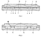
- FIG. 1 shows the cross section of a target 1, in which the erosion profile 2 resulting during operation in the final phase of using a target is shown.
- breakthrough zones 4 in which there is a risk of water ingress if e.g. the target is completely atomized in the event of a malfunction.
- the coolant channels 7 are provided with channel end membranes 10 towards the rear of the target 1, which, since they lie outside the possible breakthrough zones 4, are not exposed to direct atomization. A breakthrough in the coolant can thus be prevented.
- the cooling channels are designed in accordance with the erosion profiles of the target 1, e.g. ring-shaped.
- the attachment of the coolant channels 7 outside the breakthrough zones 4 thus reduces the risk of expecting a breakthrough into the cooling medium, in particular in the event of faults, the cooling effect which may be somewhat less due to this arrangement having virtually no effect.
- the cooling process can be controlled by means of the coolant, that is also transiently his.
- the solid material webs 8 prevent excessive deflection of a channel end membrane, since their free spans are reduced accordingly as a result of the intermediate webs. Furthermore, these webs 8 stiffen the cooling plate 6, and in addition they provide protection for the vulnerable thin duct termination membrane 10.
- FIG. 2 A direct cooling of the target is provided in FIG. 2, a cooling plate 14 being provided with open coolant channels 15. As can be seen, sealing cords 16 or the like serve for sealing. Here, too, these channels are arranged outside the breakthrough zones in order to at least reduce the risk of water ingress in the event of an accident.
- Dusting the target down to the massive part of the construction on the back of the target still leaves the possibility that the substrate will be contaminated by the construction material. This contamination is disproportionate to that which would be expected in the event of a coolant break-in. However, it is desirable to exclude even the smallest possible contamination.
- a solution to this problem is achieved by using process-tolerant construction material in the area of the expected target breakthrough and by timely switching off the process.
- Process-tolerant construction material is a material that does not adversely affect the layer quality in the event of contamination. This is therefore a question of careful material selection for the area of the construction exposed when the target breaks through. In many cases, one is sufficient Coating of this exposed area, which enables greater degrees of freedom in the choice of material for the mechanical construction as well as more cost-effective solutions.
- the target to be used then consists of this alloy with very high purity.
- copper with high purity is a good choice for the construction material in the expected target breakthrough area.
- This material allows a favorable signal evaluation without negatively influencing the process, since copper is a functional component of the layer.
- Optical and / or electrical variables can be used for signal evaluation.
- the color of the plasma discharge can be monitored as an optical variable. In the example given, the plasma over the target made of the aforementioned alloy with a dominant aluminum component has a blue color if there is no target breakthrough. If a breakthrough now occurs, some copper of the construction is exposed and activated by the plasma.
- the color of the plasma discharge changes from blue to green.
- This color change is now easy to detect using known methods in optoelectronics.
- the resulting signal can be used to trigger further activities, such as switching off the process in order to be able to change the target.
- Another possibility of signal detection is to evaluate the electrical discharge conditions that change during the breakdown. This can be done by simply measuring changes in the voltage characteristic. This is possible because the discharge voltage depends on the material is.
- a magnetron discharge with a target made of the aforementioned alloy at an operating power of 10 kW works, for example, with a discharge voltage of 550 volts.
- the copper will influence the plasma discharge and reduce the discharge voltage to approximately 500 volts. This process can be easily recorded and, as already mentioned in the optical method, evaluated.
- the entire width of the two solid material webs 8 can therefore be one fifth of the total width of the target 1, for example.
- this value can also be fallen short of, but should not be less than approx. 10%. These limits correspond to the uncooled areas of the target in the areas of greatest erosion.
- the structures described reduce the risk of water entering the vacuum when atomizing a target in the event of a fault. Possible coolant ingress during erosion of the target is avoided, thereby drastically improving the operational safety of the facility while increasing its performance.
- the present invention therefore solves the problem of an inadmissible coolant break-in and increases the reliability of the operating behavior significantly.
Landscapes
- Chemical & Material Sciences (AREA)
- Engineering & Computer Science (AREA)
- Physics & Mathematics (AREA)
- Plasma & Fusion (AREA)
- Analytical Chemistry (AREA)
- Chemical Kinetics & Catalysis (AREA)
- Materials Engineering (AREA)
- Mechanical Engineering (AREA)
- Metallurgy (AREA)
- Organic Chemistry (AREA)
- Physical Vapour Deposition (AREA)
- Physical Deposition Of Substances That Are Components Of Semiconductor Devices (AREA)
Claims (9)
- Procédé pour le refroidissement de cibles (1) dans des sources de pulvérisation, selon lequel on fait agir l'agent de refroidissement sur le côté arrière de la cible directement ou par l'intermédiaire d'une paroi en forme de feuille (10), caractérisé en ce qu'on met le côté arrière de la cible en contact avec l'agent de refroidissement directement ou par l'intermédiaire de la paroi en forme de feuille (10) exclusivement dans des zones qui ne sont pas érodées sur toute l'épaisseur en premier.
- Procédé selon la revendication 1, caractérisé en ce qu'on procède à un refroidissement non stationnaire.
- Procédé selon l'une des revendications 1 ou 2, caractérisé en ce qu'on soutient à l'aide de nervures (8) les zones (4) du côté arrière de la cible (1) qui sont menacées en premier par l'érosion sur toute l'épaisseur.
- Dispositif de refroidissement pour des cibles de sources de pulvérisation comportant une cible (1) et un dispositif de canaux (7) qui est traversé par un agent de refroidissement et qui est ouvert en direction du côté arrière de la cible, ou fermé à l'aide d'une paroi en forme de feuille, caractérisé en ce que le dispositif de canaux est formé par des canaux (7) qui s'étendent à l'extérieur des zones (4) d'érosion maximum de la cible (1).
- Dispositif de refroidissement selon la revendication 4, caractérisé en ce que les canaux de refroidissement (7) comportent chacun, au moins sur le côté tourné vers le côté arrière de la cible, une paroi de fermeture en forme de feuille (10).
- Dispositif de refroidissement selon l'une des revendications 4 ou 5, caractérisé en ce que les canaux de refroidissement (7) s'étendent dans une plaque de refroidissement (6) et sont séparés les uns des autres par des nervures (8), ces nervures (8) s'étendant dans la zone d'érosion maximum (4) de la cible (1) afin de soutenir mécaniquement ces zones (4).
- Dispositif de refroidissement selon l'une des revendications 4 à 6, caractérisé en ce que les canaux (7) sont ouverts en direction du côté arrière de la cible et sont séparés de façon étanche à l'agent de refroidissement au niveau des surfaces d'appui des nervures (8) contre la cible.
- Dispositif de refroidissement selon l'une des revendications 4 à 7, caractérisé en ce que la surface des canaux représente au moins 80 % de la surface arrière de la cible, mais au maximum 90 %.
- Dispositif de refroidissement selon la revendication 6, caractérisé en ce que les nervures sont réalisées ou revêtues à l'aide d'un matériau qui, lors d'une érosion de la cible sur toute l'épaisseur, modifie la courbe caractéristique de décharge du plasma de telle sorte que les variations de signaux optiques et électriques résultantes sont utilisables pour la détection de cet état de marche, et en ce que le matériau est choisi pour ne pas contaminer de façon gênante le processus.
Applications Claiming Priority (2)
| Application Number | Priority Date | Filing Date | Title |
|---|---|---|---|
| CH210789 | 1989-06-05 | ||
| CH2107/89 | 1989-06-05 |
Publications (2)
| Publication Number | Publication Date |
|---|---|
| EP0401622A1 EP0401622A1 (fr) | 1990-12-12 |
| EP0401622B1 true EP0401622B1 (fr) | 1995-08-23 |
Family
ID=4226037
Family Applications (1)
| Application Number | Title | Priority Date | Filing Date |
|---|---|---|---|
| EP90110019A Expired - Lifetime EP0401622B1 (fr) | 1989-06-05 | 1990-05-26 | Procédé de refroidissement de cible ainsi que dispositifs de refroidissement de cibles |
Country Status (5)
| Country | Link |
|---|---|
| US (1) | US5039913A (fr) |
| EP (1) | EP0401622B1 (fr) |
| JP (1) | JP3048059B2 (fr) |
| AT (1) | ATE126931T1 (fr) |
| DE (1) | DE59009549D1 (fr) |
Families Citing this family (17)
| Publication number | Priority date | Publication date | Assignee | Title |
|---|---|---|---|---|
| EP0512456B1 (fr) * | 1991-05-08 | 1997-06-18 | Balzers Aktiengesellschaft | Procédé de montage et démontage d'une plaque cible dans une chambre de traitement sous vide, dispositif de montage, plaque cible et chambre à vide |
| DE4242079A1 (de) * | 1992-12-14 | 1994-06-16 | Leybold Ag | Target für eine in einer evakuierbaren mit einem Prozeßgas flutbaren Prozeßkammer angeordneten Kathode |
| DE4301516C2 (de) * | 1993-01-21 | 2003-02-13 | Applied Films Gmbh & Co Kg | Targetkühlung mit Wanne |
| US5487822A (en) * | 1993-11-24 | 1996-01-30 | Applied Materials, Inc. | Integrated sputtering target assembly |
| DE4426751A1 (de) * | 1994-07-28 | 1996-02-01 | Leybold Ag | Schwimmende Zentralbefestigung, insbesondere für großflächige Sputterkatoden |
| DE19607803A1 (de) * | 1996-03-01 | 1997-09-04 | Leybold Ag | Vorrichtung zur Überwachung der Targetabnutzung von Sputterkathoden |
| US6068742A (en) * | 1996-07-22 | 2000-05-30 | Balzers Aktiengesellschaft | Target arrangement with a circular plate, magnetron for mounting the target arrangement, and process for coating a series of circular disc-shaped workpieces by means of said magnetron source |
| DE19810922A1 (de) * | 1998-03-13 | 1999-09-30 | Karlsruhe Forschzent | Gastargetfenster |
| EP1322444A4 (fr) * | 2000-09-11 | 2008-01-23 | Tosoh Smd Inc | Procede de fabrication de cibles pour pulverisation cathodique dotees de canaux de refroidissement internes |
| JP3818084B2 (ja) * | 2000-12-22 | 2006-09-06 | 日立電線株式会社 | 冷却板とその製造方法及びスパッタリングターゲットとその製造方法 |
| CN102061450A (zh) * | 2004-11-17 | 2011-05-18 | Jx日矿日石金属株式会社 | 溅射靶以及成膜装置 |
| JP4852897B2 (ja) * | 2005-06-07 | 2012-01-11 | 日立電線株式会社 | 冷却板 |
| JP4382867B1 (ja) * | 2009-01-22 | 2009-12-16 | 順 上野 | ターゲット構造及びターゲット構造の製造方法 |
| TWM416304U (en) * | 2011-07-11 | 2011-11-11 | Fu-Yi Hsu | Protective bag |
| JP5654538B2 (ja) * | 2011-09-30 | 2015-01-14 | Hoya株式会社 | 磁気ディスク用ガラス基板の製造方法及び磁気ディスクの製造方法 |
| WO2017163433A1 (fr) * | 2016-03-25 | 2017-09-28 | 技術研究組合次世代3D積層造形技術総合開発機構 | Dispositif de fabrication additive en 3d, procédé de commande d'un dispositif de fabrication additive en 3d, programme de commande d'un dispositif de fabrication additive en 3d et gabarit |
| US12609288B1 (en) * | 2022-02-03 | 2026-04-21 | Seagate Technology Llc | Sputtering targets, and related apparatuses and methods |
Family Cites Families (4)
| Publication number | Priority date | Publication date | Assignee | Title |
|---|---|---|---|---|
| US4407708A (en) * | 1981-08-06 | 1983-10-04 | Eaton Corporation | Method for operating a magnetron sputtering apparatus |
| DE3630737C1 (de) * | 1986-09-10 | 1987-11-05 | Philips & Du Pont Optical | Kathodenzerstaeubungseinrichtung mit einer Vorrichtung zur Messung eines kritischen Target-Abtrages |
| JP2537210B2 (ja) * | 1986-09-18 | 1996-09-25 | 株式会社東芝 | 高密度プラズマの発生装置 |
| US4911814A (en) * | 1988-02-08 | 1990-03-27 | Nippon Telegraph And Telephone Corporation | Thin film forming apparatus and ion source utilizing sputtering with microwave plasma |
-
1990
- 1990-05-26 EP EP90110019A patent/EP0401622B1/fr not_active Expired - Lifetime
- 1990-05-26 AT AT90110019T patent/ATE126931T1/de not_active IP Right Cessation
- 1990-05-26 DE DE59009549T patent/DE59009549D1/de not_active Expired - Fee Related
- 1990-05-31 JP JP2140125A patent/JP3048059B2/ja not_active Expired - Fee Related
- 1990-06-04 US US07/532,383 patent/US5039913A/en not_active Expired - Lifetime
Also Published As
| Publication number | Publication date |
|---|---|
| EP0401622A1 (fr) | 1990-12-12 |
| DE59009549D1 (de) | 1995-09-28 |
| ATE126931T1 (de) | 1995-09-15 |
| US5039913A (en) | 1991-08-13 |
| JPH0324265A (ja) | 1991-02-01 |
| JP3048059B2 (ja) | 2000-06-05 |
Similar Documents
| Publication | Publication Date | Title |
|---|---|---|
| EP0401622B1 (fr) | Procédé de refroidissement de cible ainsi que dispositifs de refroidissement de cibles | |
| EP0205028B1 (fr) | Appareil pour le dépôt de couches minces sur un substrat | |
| DE69926634T2 (de) | Profiliertes sputtertarget | |
| DE69928289T2 (de) | Ätzkammern mit plasma dichte und geringer kontamination und herstellungsverfahren derselben | |
| DE2102352C3 (de) | Hochfrequenzbetriebene Sprühvorrichtung | |
| DE3402971C2 (fr) | ||
| DE2517554A1 (de) | Einrichtung fuer die aufeinanderfolgende zerstaeubung von mehreren targets | |
| WO2004064122A1 (fr) | Equipement pour traiter un substrat | |
| DE3634710C2 (fr) | ||
| EP0444253B1 (fr) | Appareillage pour la déposition des couches minces sur un substrat | |
| EP0737998A2 (fr) | Dispositif de dépÔt de couches minces sur un substrat | |
| DE69715180T2 (de) | Magnetanordnung für magnetrone | |
| DE69013707T2 (de) | Verfahren zur Partikelentfernung von Substratoberflächen. | |
| EP0008634A1 (fr) | Procédé et appareillage pour le dépôt d'une couche d'un métal ou d'un alliage sur un objet conducteur d'électricité | |
| EP1580295B1 (fr) | Dispositif pour la pulvérisation réactive | |
| DE10034895C2 (de) | Verfahren zur Erkennung von Überschlägen in gepulst betriebenen Plasmen | |
| DE19646700B4 (de) | Vakuumbehandlungskammer, Vakuum-Zerstäubungsverfahren und Magnetronanordnung | |
| DE112013006746B4 (de) | Sputtergerät | |
| DE2831791A1 (de) | Bauteil aus metallischem werkstoff mit aufladungsgefaehrdeter oberflaeche und verwendung hierfuer | |
| DE102013011074A1 (de) | An eine indirekte Kühlvorrichtung angepasstes Target mit Kühlplatte | |
| EP0897189B1 (fr) | Cathode magnétron sous haute pression et dispositif comprenant une telle cathode | |
| EP0434797B1 (fr) | Appareil d'enduction de substrats par pulverisation cathodique | |
| DE202020106726U1 (de) | Vorrichtung zur elektrochemischen Oberflächenbehandlung | |
| DE19911084C2 (de) | Vorrichtung zum Behandeln von Substraten | |
| DE7606084U1 (de) | Anordnung zum zerstaeuben von festkoerpern im hochvakuum, insbesondere von dielektrischen stoffen in wechselspannungs- kathodenzerstaeubungs-anlagen |
Legal Events
| Date | Code | Title | Description |
|---|---|---|---|
| PUAI | Public reference made under article 153(3) epc to a published international application that has entered the european phase |
Free format text: ORIGINAL CODE: 0009012 |
|
| AK | Designated contracting states |
Kind code of ref document: A1 Designated state(s): AT BE CH DE ES FR GB IT LI LU NL SE |
|
| 17P | Request for examination filed |
Effective date: 19901130 |
|
| 17Q | First examination report despatched |
Effective date: 19930128 |
|
| GRAA | (expected) grant |
Free format text: ORIGINAL CODE: 0009210 |
|
| AK | Designated contracting states |
Kind code of ref document: B1 Designated state(s): AT BE CH DE ES FR GB IT LI LU NL SE |
|
| PG25 | Lapsed in a contracting state [announced via postgrant information from national office to epo] |
Ref country code: IT Free format text: LAPSE BECAUSE OF FAILURE TO SUBMIT A TRANSLATION OF THE DESCRIPTION OR TO PAY THE FEE WITHIN THE PRE;WARNING: LAPSES OF ITALIAN PATENTS WITH EFFECTIVE DATE BEFORE 2007 MAY HAVE OCCURRED AT ANY TIME BEFORE 2007. THE CORRECT EFFECTIVE DATE MAY BE DIFFERENT FROM THE ONE RECORDED.SCRIBED TIME-LIMIT Effective date: 19950823 Ref country code: ES Free format text: THE PATENT HAS BEEN ANNULLED BY A DECISION OF A NATIONAL AUTHORITY Effective date: 19950823 Ref country code: BE Effective date: 19950823 Ref country code: NL Free format text: LAPSE BECAUSE OF FAILURE TO SUBMIT A TRANSLATION OF THE DESCRIPTION OR TO PAY THE FEE WITHIN THE PRESCRIBED TIME-LIMIT Effective date: 19950823 |
|
| REF | Corresponds to: |
Ref document number: 126931 Country of ref document: AT Date of ref document: 19950915 Kind code of ref document: T |
|
| REF | Corresponds to: |
Ref document number: 59009549 Country of ref document: DE Date of ref document: 19950928 |
|
| ET | Fr: translation filed | ||
| GBT | Gb: translation of ep patent filed (gb section 77(6)(a)/1977) |
Effective date: 19951014 |
|
| PG25 | Lapsed in a contracting state [announced via postgrant information from national office to epo] |
Ref country code: SE Effective date: 19951123 |
|
| NLV1 | Nl: lapsed or annulled due to failure to fulfill the requirements of art. 29p and 29m of the patents act | ||
| PG25 | Lapsed in a contracting state [announced via postgrant information from national office to epo] |
Ref country code: LU Free format text: LAPSE BECAUSE OF NON-PAYMENT OF DUE FEES Effective date: 19960531 |
|
| PLBE | No opposition filed within time limit |
Free format text: ORIGINAL CODE: 0009261 |
|
| STAA | Information on the status of an ep patent application or granted ep patent |
Free format text: STATUS: NO OPPOSITION FILED WITHIN TIME LIMIT |
|
| 26N | No opposition filed | ||
| PGFP | Annual fee paid to national office [announced via postgrant information from national office to epo] |
Ref country code: AT Payment date: 19990512 Year of fee payment: 10 |
|
| PG25 | Lapsed in a contracting state [announced via postgrant information from national office to epo] |
Ref country code: AT Free format text: LAPSE BECAUSE OF NON-PAYMENT OF DUE FEES Effective date: 20000526 |
|
| REG | Reference to a national code |
Ref country code: GB Ref legal event code: IF02 |
|
| PGFP | Annual fee paid to national office [announced via postgrant information from national office to epo] |
Ref country code: CH Payment date: 20020826 Year of fee payment: 13 |
|
| PG25 | Lapsed in a contracting state [announced via postgrant information from national office to epo] |
Ref country code: LI Free format text: LAPSE BECAUSE OF NON-PAYMENT OF DUE FEES Effective date: 20030531 Ref country code: CH Free format text: LAPSE BECAUSE OF NON-PAYMENT OF DUE FEES Effective date: 20030531 |
|
| REG | Reference to a national code |
Ref country code: CH Ref legal event code: PL |
|
| PGFP | Annual fee paid to national office [announced via postgrant information from national office to epo] |
Ref country code: FR Payment date: 20060515 Year of fee payment: 17 |
|
| PGFP | Annual fee paid to national office [announced via postgrant information from national office to epo] |
Ref country code: DE Payment date: 20060518 Year of fee payment: 17 |
|
| PGFP | Annual fee paid to national office [announced via postgrant information from national office to epo] |
Ref country code: GB Payment date: 20060524 Year of fee payment: 17 |
|
| GBPC | Gb: european patent ceased through non-payment of renewal fee |
Effective date: 20070526 |
|
| REG | Reference to a national code |
Ref country code: FR Ref legal event code: ST Effective date: 20080131 |
|
| PG25 | Lapsed in a contracting state [announced via postgrant information from national office to epo] |
Ref country code: DE Free format text: LAPSE BECAUSE OF NON-PAYMENT OF DUE FEES Effective date: 20071201 |
|
| PG25 | Lapsed in a contracting state [announced via postgrant information from national office to epo] |
Ref country code: GB Free format text: LAPSE BECAUSE OF NON-PAYMENT OF DUE FEES Effective date: 20070526 |
|
| PG25 | Lapsed in a contracting state [announced via postgrant information from national office to epo] |
Ref country code: FR Free format text: LAPSE BECAUSE OF NON-PAYMENT OF DUE FEES Effective date: 20070531 |