EP0737998A2 - Dispositif de dépÔt de couches minces sur un substrat - Google Patents
Dispositif de dépÔt de couches minces sur un substrat Download PDFInfo
- Publication number
- EP0737998A2 EP0737998A2 EP96100953A EP96100953A EP0737998A2 EP 0737998 A2 EP0737998 A2 EP 0737998A2 EP 96100953 A EP96100953 A EP 96100953A EP 96100953 A EP96100953 A EP 96100953A EP 0737998 A2 EP0737998 A2 EP 0737998A2
- Authority
- EP
- European Patent Office
- Prior art keywords
- cathode
- hollow profiles
- substrate
- vacuum chamber
- hollow
- Prior art date
- Legal status (The legal status is an assumption and is not a legal conclusion. Google has not performed a legal analysis and makes no representation as to the accuracy of the status listed.)
- Withdrawn
Links
- 239000000758 substrate Substances 0.000 title claims abstract description 23
- 238000000151 deposition Methods 0.000 title 1
- 238000000034 method Methods 0.000 claims abstract description 48
- 239000002826 coolant Substances 0.000 claims abstract description 11
- 238000004544 sputter deposition Methods 0.000 claims abstract description 10
- 238000007789 sealing Methods 0.000 claims description 12
- 239000013013 elastic material Substances 0.000 claims description 2
- 239000002184 metal Substances 0.000 claims description 2
- 239000002245 particle Substances 0.000 claims 1
- 125000006850 spacer group Chemical group 0.000 description 5
- 238000004519 manufacturing process Methods 0.000 description 4
- 239000003638 chemical reducing agent Substances 0.000 description 2
- 238000012423 maintenance Methods 0.000 description 2
- 206010052128 Glare Diseases 0.000 description 1
- 229910000831 Steel Inorganic materials 0.000 description 1
- 239000004809 Teflon Substances 0.000 description 1
- 229920006362 Teflon® Polymers 0.000 description 1
- 238000001816 cooling Methods 0.000 description 1
- 230000007257 malfunction Effects 0.000 description 1
- 238000005488 sandblasting Methods 0.000 description 1
- 229910000679 solder Inorganic materials 0.000 description 1
- 239000010959 steel Substances 0.000 description 1
- 238000004804 winding Methods 0.000 description 1
Images


Classifications
-
- H—ELECTRICITY
- H01—ELECTRIC ELEMENTS
- H01J—ELECTRIC DISCHARGE TUBES OR DISCHARGE LAMPS
- H01J37/00—Discharge tubes with provision for introducing objects or material to be exposed to the discharge, e.g. for the purpose of examination or processing thereof
- H01J37/32—Gas-filled discharge tubes
- H01J37/32431—Constructional details of the reactor
- H01J37/3244—Gas supply means
-
- H—ELECTRICITY
- H01—ELECTRIC ELEMENTS
- H01J—ELECTRIC DISCHARGE TUBES OR DISCHARGE LAMPS
- H01J9/00—Apparatus or processes specially adapted for the manufacture, installation, removal, maintenance of electric discharge tubes, discharge lamps, or parts thereof; Recovery of material from discharge tubes or lamps
- H01J9/02—Manufacture of electrodes or electrode systems
- H01J9/18—Assembling together the component parts of electrode systems
-
- H—ELECTRICITY
- H01—ELECTRIC ELEMENTS
- H01J—ELECTRIC DISCHARGE TUBES OR DISCHARGE LAMPS
- H01J37/00—Discharge tubes with provision for introducing objects or material to be exposed to the discharge, e.g. for the purpose of examination or processing thereof
- H01J37/32—Gas-filled discharge tubes
- H01J37/34—Gas-filled discharge tubes operating with cathodic sputtering
- H01J37/3411—Constructional aspects of the reactor
- H01J37/3438—Electrodes other than cathode
Definitions
- the invention relates to a device for applying thin layers to a substrate by means of the sputtering method in a vacuum chamber, through which the substrate to be coated can be moved and with a screen arranged between a cathode to be sputtered and an anode, the substrate plane running below the anode, and wherein from the wall of the vacuum chamber, provided with channels, hollow profiles - parallel to the cathode plane and in the area between the cathode and the anode - are provided, which are flowed through by a cooling medium and by a process gas, the channels for the process gas having openings which are transverse run to the longitudinal axis of this channel and allow process gas to escape into the vacuum chamber.
- a device for applying thin layers to a substrate by means of the cathode sputtering method is known (EP 0 205 028).
- a mechanical screen is provided between the cathode to be atomized and the anode, which divides the space between the cathode and the substrate to be coated.
- This device is provided with several separate cooling tubes and gas line tubes for the supply of temperature control medium and process gas.
- This known device has the disadvantage that the supply and return of the temperature control medium and the supply of process gas each take place via separate, multi-piece pipelines and are therefore very susceptible to malfunctions and expensive to manufacture and maintain.
- the pipes have bends, windings, screw connections and solder joints that are in a vacuum under the operating conditions of the device, which leads to hairline cracks and leaks in the pipes due to the additional influence of process-related heat.
- These leaks initially impair the layer quality, for example the adhesiveness of the layer to be applied to the substrate during the sputtering process (sputtering) and subsequently and inevitably lead to total failure of the entire system, which is always associated with considerable effort and immense costs.
- the present invention has for its object to improve the known device so that the replacement of the anodes and screens can be easily done from the top of the process chamber without the use of tools and without eye contact.
- the service life of the anodes and the thermal resistance of the screens are to be improved.
- anodes designed as profile rails with an L-shaped cross section, the short legs of which are each supported overlapping the hollow profiles on the top sides of the hollow profiles and are held in this position by bolts which extend upwards from the top sides to extend and correspond to holes in the short legs.
- Each approximately plate-shaped diaphragm preferably has two legs on its section facing the process chamber wall, one of which legs Leg is supported with its end face on the process chamber wall and the other leg is approximately hook-shaped and with its free end or a nose arranged at this end engages over a strip attached to the process chamber wall or a hollow profile.
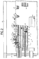
- FIG. 1 there are further vacuum chambers 1 ', 1' 'to the side of the rectangular vacuum chamber 1, which are connected to one another in a line via locks (not shown in detail) in the process chamber walls 2, 3.
- the anodes 4, 5 are arranged parallel to one another and transversely to the substrate transport direction and to the direction of extension of the chambers 1, 1 'and 1' 'in such a way that the rectangular hollow profiles 6, 7 and the screens 8, 9 are aligned with the center of the chamber , wherein the channels for the coolant inlet 6a, 7a and return 6b, 7b are arranged in the hollow profiles, in which in turn the gas distributor pipes 6f, 7f are centrally attached. Furthermore, the channels for process gas 6d, 7d, ... on the underside with openings 6e, 6e ', ... which repeat at certain intervals; 7e, 7e ', ... for the exit of the process gas from the channels 6d, 7d into the vacuum chamber 1.
- the substrate 10 can be moved below the anodes 4, 5 on the horizontally extending substrate plane 11 and in the direction of movement A through the vacuum chambers 1, 1 ', 1' ',...
- the cathode 12 with its flat target 35 is located above and between the screens 8, 9 and extends parallel to the hollow profiles 6, 7 and thus transversely to the direction of movement A of the substrate.
- the two Z-shaped sealing / guide plates 13, 14 are arranged such that they close the gaps remaining between the hollow profiles 6, 7 and the process chamber walls 2, 3 of the vacuum chamber 1 together with the sealing tubes 30, 31 made of elastic material.
- the hollow profiles 6, 7 are electrically insulated via insulating plates 15, 15 'and firmly connected to the process chamber walls 2, 3 by means of the screws 16, 17 and spacer plates 20, 20', for which purpose the screws 16, 17 in turn are enclosed by insulating bushes 18, 19 are.
- the anodes 4, 5 are shaped as L-profiles and each lie with their short legs 4a, 5a on the upper surfaces of the hollow profiles 6, 7, where they are anchored in the hollow profiles 6, 7 with bolts 21, 21 ', ... locked and clamped with wing screws 32, 32 ', ...
- the wing screws 32, 32 ', ... which are easily accessible through the upper opening 28 which can be closed by a cover 23, are held for this purpose by strips 24, 24', which in turn - as can be seen clearly in FIG. 2 - via spacer bushings 25 , 25 ', ... are screwed to the hollow profiles 6 and 7, respectively.
- each Panel 26, 27 each consists of a bottom part 26 ', 27', an end wall part 26 '', 27 '', a side wall part 26 ''',27''' and a collar part 26 x , 27 x .
- each hollow profile 6, 7 extending strip 24, 24 'each has a plurality of threaded bores for wing nuts 32, 32', ..., the threaded bolts of which rest on the bent legs 4a and 5a of the anodes 4, 5 and these immovably on the Hold hollow sections 6, 7.
- each hollow profile 6, 7 there is in each case an aperture 8 or 9, which essentially consists of a first leg 8 'or 9' extending parallel to the cathode 12 or its target surface 35 and an angle thereof extending from this hook-like second leg 8 ′′ or 9 ′′, which extends approximately 45 ° upwards.
- first leg 8 'or 9' with its end facing away from the cathode 12 bears against the process chamber wall 2 or 3 or against a hollow profile 38 or 39 which extends parallel to the hollow profile 6 or 7, the upper end of the second leg 8 ′′ or 9 ′′ with a nose-shaped extension 37, 37 ′ the top of the hollow profile 38 or 39 or its finger-like perpendicular extension 40 or 40 ′, the hollow profile 38, 39 with the process chamber wall 2, 3 is screwed and is sealed with the aid of a sealing hose 41, 42 against the process chamber wall.
- the lance or the gas distributor pipe 6f or 7f is distributed over its length, and is longitudinally displaceable on the pipe Locking disks 43, 43 ', ..., which can be fastened with the aid of clamping pieces 44, 44', ... to precisely definable sections of the gas distributor pipe 6f or 7f, so that the parts or sections 6d, 6d separated from the locking disks ', ... or 7d, 7d', ... can be supplied individually with gas, which enables the individual nozzles 6e, 6e ', ... or 7e, 7e', ... with different gas flows to supply.
- the anodes are covered comparatively quickly with an insulating layer during the sputtering process, which considerably limits their service life.
- the coated anodes must then be regularly removed from the process chamber and removed from the insulating layer, for example by sandblasting, which means a significant time delay in the production process.
- the anodes 4, 5 according to the invention can be made of steel, which increases their service life. They can be removed particularly easily after loosening the wing screws 32, 32 ', ... through the opening 28 from the chamber 1, 1', ..., which leads to a reduction in the maintenance time of the system.
Landscapes
- Engineering & Computer Science (AREA)
- Physics & Mathematics (AREA)
- Plasma & Fusion (AREA)
- Chemical & Material Sciences (AREA)
- Analytical Chemistry (AREA)
- Manufacturing & Machinery (AREA)
- Physical Vapour Deposition (AREA)
- Physical Deposition Of Substances That Are Components Of Semiconductor Devices (AREA)
Priority Applications (1)
| Application Number | Priority Date | Filing Date | Title |
|---|---|---|---|
| EP99112252A EP0957507A1 (fr) | 1995-04-11 | 1996-01-24 | Dispositif de dépÔt de couches minces sur un substrat |
Applications Claiming Priority (2)
| Application Number | Priority Date | Filing Date | Title |
|---|---|---|---|
| DE19513691A DE19513691A1 (de) | 1995-04-11 | 1995-04-11 | Vorrichtung zum Aufbringen dünner Schichten auf ein Substrat |
| DE19513691 | 1995-04-11 |
Related Child Applications (1)
| Application Number | Title | Priority Date | Filing Date |
|---|---|---|---|
| EP99112252A Division EP0957507A1 (fr) | 1995-04-11 | 1996-01-24 | Dispositif de dépÔt de couches minces sur un substrat |
Publications (2)
| Publication Number | Publication Date |
|---|---|
| EP0737998A2 true EP0737998A2 (fr) | 1996-10-16 |
| EP0737998A3 EP0737998A3 (fr) | 1998-05-13 |
Family
ID=7759457
Family Applications (2)
| Application Number | Title | Priority Date | Filing Date |
|---|---|---|---|
| EP99112252A Withdrawn EP0957507A1 (fr) | 1995-04-11 | 1996-01-24 | Dispositif de dépÔt de couches minces sur un substrat |
| EP96100953A Withdrawn EP0737998A3 (fr) | 1995-04-11 | 1996-01-24 | Dispositif de dépÔt de couches minces sur un substrat |
Family Applications Before (1)
| Application Number | Title | Priority Date | Filing Date |
|---|---|---|---|
| EP99112252A Withdrawn EP0957507A1 (fr) | 1995-04-11 | 1996-01-24 | Dispositif de dépÔt de couches minces sur un substrat |
Country Status (9)
| Country | Link |
|---|---|
| US (1) | US5662784A (fr) |
| EP (2) | EP0957507A1 (fr) |
| JP (1) | JPH08291383A (fr) |
| KR (1) | KR100230072B1 (fr) |
| CN (1) | CN1068639C (fr) |
| BR (1) | BR9601309A (fr) |
| CA (1) | CA2173891A1 (fr) |
| DE (2) | DE19513691A1 (fr) |
| TW (1) | TW402166U (fr) |
Cited By (1)
| Publication number | Priority date | Publication date | Assignee | Title |
|---|---|---|---|---|
| EP0872573A1 (fr) * | 1997-04-12 | 1998-10-21 | Leybold Systems GmbH | Dispositif de traitement sous vide de dépÔt de couches minces |
Families Citing this family (20)
| Publication number | Priority date | Publication date | Assignee | Title |
|---|---|---|---|---|
| DE19734079A1 (de) * | 1997-08-07 | 1999-02-11 | Leybold Systems Gmbh | Kathode für eine Vorrichtung zum Zerstäuben eines Targets |
| DE19741708A1 (de) * | 1997-09-22 | 1999-04-01 | Leybold Systems Gmbh | Vorrichtung zum Aufbringen dünner Schichten auf ein Substrat |
| DE29717418U1 (de) * | 1997-09-26 | 1998-01-22 | Leybold Systems GmbH, 63450 Hanau | Vorrichtung zum Aufbringen dünner Schichten auf ein Substrat |
| DE19755837A1 (de) * | 1997-12-16 | 1999-06-17 | Leybold Ag | Sputteranlage |
| US6943066B2 (en) * | 2002-06-05 | 2005-09-13 | Advantech Global, Ltd | Active matrix backplane for controlling controlled elements and method of manufacture thereof |
| US7166199B2 (en) * | 2002-12-18 | 2007-01-23 | Cardinal Cg Company | Magnetron sputtering systems including anodic gas distribution systems |
| US7879209B2 (en) * | 2004-08-20 | 2011-02-01 | Jds Uniphase Corporation | Cathode for sputter coating |
| US8500973B2 (en) * | 2004-08-20 | 2013-08-06 | Jds Uniphase Corporation | Anode for sputter coating |
| US20080308417A1 (en) * | 2005-03-14 | 2008-12-18 | Toyoaki Hirata | Sputtering Apparatus |
| KR101174146B1 (ko) * | 2005-06-28 | 2012-08-14 | 엘지디스플레이 주식회사 | 스퍼터링 장치 |
| US7850828B2 (en) * | 2006-09-15 | 2010-12-14 | Cardinal Cg Company | Enhanced virtual anode |
| US8557093B2 (en) * | 2007-03-22 | 2013-10-15 | Sunpower Corporation | Deposition system with electrically isolated pallet and anode assemblies |
| EP2103709A1 (fr) * | 2008-02-28 | 2009-09-23 | Applied Materials, Inc. | Dispositif et procédé de prévention de revêtement à l'envers |
| EP2096192A1 (fr) * | 2008-02-28 | 2009-09-02 | Applied Materials, Inc. | Dispositif et procédé de prévention de revêtement à l'envers. |
| CN102002675B (zh) * | 2009-08-28 | 2013-07-03 | 鸿富锦精密工业(深圳)有限公司 | 真空溅镀设备的进气装置 |
| CN102623656A (zh) * | 2012-04-06 | 2012-08-01 | 西北工业大学 | 一种用于水下航行器电池组的固定器 |
| CN103898462B (zh) * | 2012-12-29 | 2017-08-22 | 深圳富泰宏精密工业有限公司 | 磁控溅射镀膜装置 |
| DE102013204132B4 (de) * | 2013-03-11 | 2015-04-02 | Von Ardenne Gmbh | Vorrichtung zur Anodenhalterung beim Magnetron-Sputtern |
| JP6189122B2 (ja) * | 2013-07-19 | 2017-08-30 | 日東電工株式会社 | スパッタ装置 |
| EP3254296B1 (fr) | 2015-02-03 | 2021-04-14 | Cardinal CG Company | Appareil de pulvérisation comprenant un système de distribution de gaz |
Family Cites Families (7)
| Publication number | Priority date | Publication date | Assignee | Title |
|---|---|---|---|---|
| DE2522227A1 (de) * | 1975-05-20 | 1976-12-02 | Telic Corp | Verfahren und vorrichtung zur erzeugung einer glimmentladung |
| US4407708A (en) * | 1981-08-06 | 1983-10-04 | Eaton Corporation | Method for operating a magnetron sputtering apparatus |
| US4425218A (en) * | 1982-03-30 | 1984-01-10 | Shatterproof Glass Corporation | Gas distribution system for sputtering cathodes |
| DE3521053A1 (de) * | 1985-06-12 | 1986-12-18 | Leybold-Heraeus GmbH, 5000 Köln | Vorrichtung zum aufbringen duenner schichten auf ein substrat |
| DE3800449A1 (de) * | 1988-01-09 | 1989-07-20 | Leybold Ag | Verfahren und einrichtung zur herstellung magnetooptischer, speicher- und loeschfaehiger datentraeger |
| US4849087A (en) * | 1988-02-11 | 1989-07-18 | Southwall Technologies | Apparatus for obtaining transverse uniformity during thin film deposition on extended substrate |
| DE4006411C2 (de) * | 1990-03-01 | 1997-05-28 | Leybold Ag | Vorrichtung zum Aufbringen dünner Schichten auf ein Substrat |
-
1995
- 1995-04-11 DE DE19513691A patent/DE19513691A1/de not_active Withdrawn
- 1995-04-25 DE DE19515088A patent/DE19515088A1/de not_active Withdrawn
-
1996
- 1996-01-24 EP EP99112252A patent/EP0957507A1/fr not_active Withdrawn
- 1996-01-24 EP EP96100953A patent/EP0737998A3/fr not_active Withdrawn
- 1996-02-10 TW TW088201776U patent/TW402166U/zh not_active IP Right Cessation
- 1996-03-25 US US08/622,443 patent/US5662784A/en not_active Expired - Fee Related
- 1996-04-04 KR KR1019960010160A patent/KR100230072B1/ko not_active Expired - Fee Related
- 1996-04-10 BR BR9601309A patent/BR9601309A/pt not_active IP Right Cessation
- 1996-04-10 JP JP8088587A patent/JPH08291383A/ja active Pending
- 1996-04-11 CN CN96105547A patent/CN1068639C/zh not_active Expired - Fee Related
- 1996-04-11 CA CA002173891A patent/CA2173891A1/fr not_active Abandoned
Cited By (1)
| Publication number | Priority date | Publication date | Assignee | Title |
|---|---|---|---|---|
| EP0872573A1 (fr) * | 1997-04-12 | 1998-10-21 | Leybold Systems GmbH | Dispositif de traitement sous vide de dépÔt de couches minces |
Also Published As
| Publication number | Publication date |
|---|---|
| KR100230072B1 (ko) | 1999-11-15 |
| DE19513691A1 (de) | 1996-10-17 |
| EP0957507A1 (fr) | 1999-11-17 |
| CA2173891A1 (fr) | 1996-10-12 |
| KR960039050A (ko) | 1996-11-21 |
| JPH08291383A (ja) | 1996-11-05 |
| CN1068639C (zh) | 2001-07-18 |
| DE19515088A1 (de) | 1997-01-02 |
| US5662784A (en) | 1997-09-02 |
| BR9601309A (pt) | 1998-01-13 |
| EP0737998A3 (fr) | 1998-05-13 |
| CN1140206A (zh) | 1997-01-15 |
| TW402166U (en) | 2000-08-11 |
Similar Documents
| Publication | Publication Date | Title |
|---|---|---|
| EP0737998A2 (fr) | Dispositif de dépÔt de couches minces sur un substrat | |
| EP0444253B1 (fr) | Appareillage pour la déposition des couches minces sur un substrat | |
| EP1420912B1 (fr) | Dispositif pour refroidir de la matiere par production d'un jet plan | |
| DE3229694A1 (de) | Kuehler | |
| EP0811818A1 (fr) | Plaque de grille et procédé pour sa fabrication | |
| EP0942792B1 (fr) | Dispositif pour le refroidissement de profiles files | |
| EP3463705A1 (fr) | Dispositif de lubrification destiné à appliquer un lubrifiant lors du laminage d'un produit à laminer | |
| DE19733940C2 (de) | Vorrichtung zum Beschichten von plattenförmigen Substraten mit dünnen Schichten mittels Kathodenzerstäubung | |
| DE3015282C2 (de) | Vorrichtung zum partiellen Galvanisieren von leitenden oder leitend gemachten Oberflächen | |
| DE19736318C2 (de) | Vorrichtung zum Beschichten von plattenförmigen Substraten mit dünnen Schichten mittels Kathodenzerstäubung | |
| CH624793A5 (fr) | ||
| DE2840293C3 (de) | Korrosionsschutz für einen Plattenwärmetauscher | |
| DE29717418U1 (de) | Vorrichtung zum Aufbringen dünner Schichten auf ein Substrat | |
| DE102012000397B4 (de) | Vorrichtung mit einem Befestigungsmittel in einer Vakuumbehandlungsanlage | |
| DE19508406A1 (de) | Kathodenanordnung für eine Vorrichtung zum Zerstäuben eines Target-Paares | |
| DE4337342A1 (de) | Vorrichtung zum Kühlen von Walzbändern | |
| EP3638821B1 (fr) | Pièce en forme de trompe pour une installation de revêtement par galvanisation à chaud | |
| EP3129522B1 (fr) | Dispositif de distribution de gaz d'une chambre à vide équipé d'un moyen de guidage de gaz | |
| EP3638822B1 (fr) | Dispositif et procédé de séparation d'atmosphères de gaz | |
| EP1601442B1 (fr) | Unite separateur de gouttes et laveur de gaz de fumee equipe de cette unite | |
| DE19756162C2 (de) | Sputtereinrichtung | |
| EP3591088B1 (fr) | Dispositif de revêtement par immersion à chaud d'une bande métallique | |
| DE3825839A1 (de) | Vorrichtung zum kuehlen und zum hydraulischen transport von unsymmetrischen walzprofilen | |
| WO2006074624A1 (fr) | Canal de pompage pour une installation de dépôt sous vide à extension longitudinale | |
| DE19546114A1 (de) | Vorrichtung zum Aufbringen dünner, insbesondere reakitver Metallschichten auf ein Substrat |
Legal Events
| Date | Code | Title | Description |
|---|---|---|---|
| PUAI | Public reference made under article 153(3) epc to a published international application that has entered the european phase |
Free format text: ORIGINAL CODE: 0009012 |
|
| AK | Designated contracting states |
Kind code of ref document: A2 Designated state(s): AT BE DE ES FR GB IT LU NL SE |
|
| PUAL | Search report despatched |
Free format text: ORIGINAL CODE: 0009013 |
|
| AK | Designated contracting states |
Kind code of ref document: A3 Designated state(s): AT BE DE ES FR GB IT LU NL SE |
|
| 17P | Request for examination filed |
Effective date: 19980528 |
|
| 17Q | First examination report despatched |
Effective date: 19990305 |
|
| GRAG | Despatch of communication of intention to grant |
Free format text: ORIGINAL CODE: EPIDOS AGRA |
|
| GRAG | Despatch of communication of intention to grant |
Free format text: ORIGINAL CODE: EPIDOS AGRA |
|
| GRAH | Despatch of communication of intention to grant a patent |
Free format text: ORIGINAL CODE: EPIDOS IGRA |
|
| GRAG | Despatch of communication of intention to grant |
Free format text: ORIGINAL CODE: EPIDOS AGRA |
|
| GRAH | Despatch of communication of intention to grant a patent |
Free format text: ORIGINAL CODE: EPIDOS IGRA |
|
| RAP1 | Party data changed (applicant data changed or rights of an application transferred) |
Owner name: APPLIED FILMS GMBH & CO. KG |
|
| STAA | Information on the status of an ep patent application or granted ep patent |
Free format text: STATUS: THE APPLICATION IS DEEMED TO BE WITHDRAWN |
|
| 18D | Application deemed to be withdrawn |
Effective date: 20010731 |