EP0401654B1 - Dispositif de couplage et/ou découplage des rayons lumineux avec élément d'optique intégré - Google Patents
Dispositif de couplage et/ou découplage des rayons lumineux avec élément d'optique intégré Download PDFInfo
- Publication number
- EP0401654B1 EP0401654B1 EP90110217A EP90110217A EP0401654B1 EP 0401654 B1 EP0401654 B1 EP 0401654B1 EP 90110217 A EP90110217 A EP 90110217A EP 90110217 A EP90110217 A EP 90110217A EP 0401654 B1 EP0401654 B1 EP 0401654B1
- Authority
- EP
- European Patent Office
- Prior art keywords
- coupling
- grating
- photoelectric device
- diffraction
- integrated optical
- Prior art date
- Legal status (The legal status is an assumption and is not a legal conclusion. Google has not performed a legal analysis and makes no representation as to the accuracy of the status listed.)
- Expired - Lifetime
Links
- 230000003287 optical effect Effects 0.000 title claims abstract description 24
- 230000008878 coupling Effects 0.000 title claims abstract description 18
- 238000010168 coupling process Methods 0.000 title claims abstract description 18
- 238000005859 coupling reaction Methods 0.000 title claims abstract description 18
- 238000005286 illumination Methods 0.000 claims 2
- 238000005259 measurement Methods 0.000 abstract description 2
- 239000013307 optical fiber Substances 0.000 description 3
- 239000000758 substrate Substances 0.000 description 3
- 238000005516 engineering process Methods 0.000 description 1
- 230000002452 interceptive effect Effects 0.000 description 1
- 238000004519 manufacturing process Methods 0.000 description 1
Images


Classifications
-
- G—PHYSICS
- G02—OPTICS
- G02B—OPTICAL ELEMENTS, SYSTEMS OR APPARATUS
- G02B6/00—Light guides; Structural details of arrangements comprising light guides and other optical elements, e.g. couplings
- G02B6/10—Light guides; Structural details of arrangements comprising light guides and other optical elements, e.g. couplings of the optical waveguide type
- G02B6/12—Light guides; Structural details of arrangements comprising light guides and other optical elements, e.g. couplings of the optical waveguide type of the integrated circuit kind
- G02B6/122—Basic optical elements, e.g. light-guiding paths
- G02B6/124—Geodesic lenses or integrated gratings
-
- G—PHYSICS
- G01—MEASURING; TESTING
- G01D—MEASURING NOT SPECIALLY ADAPTED FOR A SPECIFIC VARIABLE; ARRANGEMENTS FOR MEASURING TWO OR MORE VARIABLES NOT COVERED IN A SINGLE OTHER SUBCLASS; TARIFF METERING APPARATUS; MEASURING OR TESTING NOT OTHERWISE PROVIDED FOR
- G01D5/00—Mechanical means for transferring the output of a sensing member; Means for converting the output of a sensing member to another variable where the form or nature of the sensing member does not constrain the means for converting; Transducers not specially adapted for a specific variable
- G01D5/26—Mechanical means for transferring the output of a sensing member; Means for converting the output of a sensing member to another variable where the form or nature of the sensing member does not constrain the means for converting; Transducers not specially adapted for a specific variable characterised by optical transfer means, i.e. using infrared, visible, or ultraviolet light
- G01D5/32—Mechanical means for transferring the output of a sensing member; Means for converting the output of a sensing member to another variable where the form or nature of the sensing member does not constrain the means for converting; Transducers not specially adapted for a specific variable characterised by optical transfer means, i.e. using infrared, visible, or ultraviolet light with attenuation or whole or partial obturation of beams of light
- G01D5/34—Mechanical means for transferring the output of a sensing member; Means for converting the output of a sensing member to another variable where the form or nature of the sensing member does not constrain the means for converting; Transducers not specially adapted for a specific variable characterised by optical transfer means, i.e. using infrared, visible, or ultraviolet light with attenuation or whole or partial obturation of beams of light the beams of light being detected by photocells
- G01D5/36—Forming the light into pulses
- G01D5/38—Forming the light into pulses by diffraction gratings
-
- G—PHYSICS
- G02—OPTICS
- G02B—OPTICAL ELEMENTS, SYSTEMS OR APPARATUS
- G02B6/00—Light guides; Structural details of arrangements comprising light guides and other optical elements, e.g. couplings
- G02B6/24—Coupling light guides
- G02B6/26—Optical coupling means
- G02B6/34—Optical coupling means utilising prism or grating
Definitions
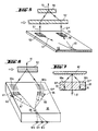
- Vertical incident partial beams 51 'and 51 ⁇ also meet in this example circular gratings 53 and 54 which they lead to a coupler 59 in the indicated optical fibers 57 and 58.
Landscapes
- Physics & Mathematics (AREA)
- General Physics & Mathematics (AREA)
- Optics & Photonics (AREA)
- Engineering & Computer Science (AREA)
- Microelectronics & Electronic Packaging (AREA)
- Optical Transform (AREA)
- Optical Couplings Of Light Guides (AREA)
- Length Measuring Devices By Optical Means (AREA)
- Optical Integrated Circuits (AREA)
- Semiconductor Lasers (AREA)
- Exposure And Positioning Against Photoresist Photosensitive Materials (AREA)
- Mounting And Adjusting Of Optical Elements (AREA)
Claims (10)
- Dispositif photo-électrique pour l'entrée et/ou la sortie de rayons lumineux comportant un organe optique intégré (5, 25 35, 45, 55, 65, 85), une source lumnineuse et au moins un organe de diffraction (2, 26, 36 46, 56; 62, 82) produisant au moins un faisceau de rayons diffractés (21′ à 81˝) et comportant en outre au moins un organe d'entrée et/ou de sortie (3, 4, 23, 24, 33, 34, 43, 44, 53, 54, 63, 64, 83, 84) pour l'entrée et/ou la sortie du faisceau de rayons diffractés (21′ à 81˝) dans et/ou hors d'une fibre optique (27, 28, 57, 58, 67, 68, 81 a), caractérisé par le fait que l'organe de d'entrée et/ou de sortie est constitué par un réseau circulaire (23 à 84) et qu'il est prévu au moins un organe de diffraction (22 à 82) supplémentaire qui est accordé sur le premier organe de diffraction (26 à 86b) de manière telle que le faisceau de rayons diffractés (21′ à 81˝) entre dans le réseau circulaire (23 à 84) ou sorte du réseau circulaire (81b) perpendiculairement auxdits réseaux.
- Dispositif photo-électrique selon la revendication 1, caractérisé par le fait que le premier organe de diffraction est agencé en réseau de diffraction (26 à 82) qui produit deux faisceaux partiels (21′ à 81˝) de rayons symétriques et que l'organe de diffraction supplémentaire est lui aussi agencé en réseau de diffraction (22 à 86b) dont la constante de réseau coïncide avec celle du premier réseau de diffraction (26 à 82), de manière telle que les faisceaux partiels (21′ à 81˝) de rayons diffractés entrent perpendiculairennent dans deux réseaux circulaires (23 à 84).
- Dispositif photo-électrique selon la revendication 2, caractérisé par le fait qu'un des réseaux de diffraction (22 à 82) est une mesure matérialisée d'un dispositif photo-électrique de mesure de position.
- Dispositif photo-électrique selon la revendication 3, caractérisé par le fait que la mesure matérialisée (22 à 82) et le réseau de diffraction supplémentaire (26 à 86b) sont agencés en réseau linéaire.
- Dispositif photo-électrique selon la revendication 3, caractérisé par le fait que la mesure matérialisée est agencée en réseau radial.
- Dispositif photo-électrique selon la revendication 4, caractérisé par le fait que les réseaux circulaires (23 à 84) et au moins l'un des réseaux de diffraction (26 à 86b) font partie d'un organe optique intégré (25 à 85).
- Dispositif photo-électrique selon la revendication 6, caractérisé par, le fait que l'organe optique intégré (25 à 85b) comporte un coupleur (29 à 69) dans lequel les faisceaux partiels (21′ à 81˝) de rayons entrants sont amenés en interférence, sont détectés par des capteurs (210 à 612) et sont transformés en signaux électriques mutuellement déphasés.
- Dispositif photo-électrique selon la revendication 7, caractérisé par le fait que les capteurs (210 à 612) sont des organes intégrés dans l'organe optique intégré (25 à 85).
- Dispositif photo-électrique selon la revendication 6, caractérisé par le fait que l'organe optique intégré contient également la source lumineuse.
- Dispositif photo-électrique selon la revendication 6, caractérisé par le fait que le faisceau de rayons lumineux (81) est amené par l'intermédiaire d'une fibre optique (81a) à un réseau circulaire (81b) de sortie qui dévie ledit faisceau de manière telle que celui-ci arrive perpendiculairement sur la mesure matérialisée (82).
Priority Applications (1)
| Application Number | Priority Date | Filing Date | Title |
|---|---|---|---|
| AT90110217T ATE85705T1 (de) | 1989-06-08 | 1990-05-30 | Vorrichtung zum ein- und/oder auskoppeln von lichtstrahlen mit einem integriert-optischen baustein. |
Applications Claiming Priority (2)
| Application Number | Priority Date | Filing Date | Title |
|---|---|---|---|
| DE3918726 | 1989-06-08 | ||
| DE3918726A DE3918726C1 (fr) | 1989-06-08 | 1989-06-08 |
Publications (3)
| Publication Number | Publication Date |
|---|---|
| EP0401654A2 EP0401654A2 (fr) | 1990-12-12 |
| EP0401654A3 EP0401654A3 (fr) | 1991-03-27 |
| EP0401654B1 true EP0401654B1 (fr) | 1993-02-10 |
Family
ID=6382358
Family Applications (1)
| Application Number | Title | Priority Date | Filing Date |
|---|---|---|---|
| EP90110217A Expired - Lifetime EP0401654B1 (fr) | 1989-06-08 | 1990-05-30 | Dispositif de couplage et/ou découplage des rayons lumineux avec élément d'optique intégré |
Country Status (5)
| Country | Link |
|---|---|
| US (1) | US5127733A (fr) |
| EP (1) | EP0401654B1 (fr) |
| JP (1) | JPH07119854B2 (fr) |
| AT (1) | ATE85705T1 (fr) |
| DE (2) | DE3918726C1 (fr) |
Cited By (1)
| Publication number | Priority date | Publication date | Assignee | Title |
|---|---|---|---|---|
| EP3792668B1 (fr) * | 2019-09-10 | 2021-12-15 | Sick Ag | Capteur optoélectronique et procédé de détection des objets dans une zone de surveillance |
Families Citing this family (18)
| Publication number | Priority date | Publication date | Assignee | Title |
|---|---|---|---|---|
| DE4013566A1 (de) * | 1990-04-27 | 1991-11-07 | Heidenhain Gmbh Dr Johannes | Winkelmesseinrichtung |
| KR100254024B1 (ko) * | 1990-07-23 | 2000-06-01 | 가나이 쓰도무 | 반도체 장치의 제조 방법 |
| DE59102268D1 (de) * | 1991-05-24 | 1994-08-25 | Heidenhain Gmbh Dr Johannes | Vorrichtung zum Ein- und/oder Auskoppeln von Lichtstrahlen mit einem integriert-optischen Baustein. |
| DE4205750A1 (de) * | 1992-02-25 | 1993-08-26 | Siemens Ag | Optischer demultiplexer |
| DE4209672C1 (en) * | 1992-03-25 | 1993-07-08 | Deutsche Aerospace Ag, 8000 Muenchen, De | Wavelength measuring device for spectrometry - has sandwich structure of optical waveguides with diffraction gratings of differing constant giving spatial separation of components |
| JP3210111B2 (ja) * | 1992-12-24 | 2001-09-17 | キヤノン株式会社 | 変位検出装置 |
| DE4302313C2 (de) * | 1993-01-28 | 1996-12-05 | Heidenhain Gmbh Dr Johannes | Mehrkoordinaten-Meßeinrichtung |
| EP0625690B1 (fr) * | 1993-05-21 | 1996-04-03 | Dr. Johannes Heidenhain GmbH | Dispositif de mesure de position optoélectrique |
| US5507455A (en) * | 1993-12-28 | 1996-04-16 | Yang; Ro-King | Automatic control device for flying state of remote-control toy airplane |
| WO1996002009A1 (fr) * | 1994-07-08 | 1996-01-25 | Forskningscenter Risø | Appareil et procede de mesure optique |
| DE19726397A1 (de) * | 1997-06-21 | 1998-12-24 | Heidenhain Gmbh Dr Johannes | Strichplatte und optische Einrichtung mit einer beleuchtbaren Strichplatte |
| US7129508B2 (en) * | 2002-01-18 | 2006-10-31 | Honeywell International Inc. | Compact VCSEL sensor with multiple sensing capabilities |
| JP2011107384A (ja) * | 2009-11-17 | 2011-06-02 | Nec Corp | 光結合デバイスの製造方法 |
| US9162404B2 (en) * | 2011-03-05 | 2015-10-20 | Alcatel Lucent | Radial optical coupler |
| US8682120B2 (en) | 2011-03-05 | 2014-03-25 | Alcatel Lucent | Polarization-independent grating optical coupler |
| US9140854B2 (en) | 2011-09-22 | 2015-09-22 | Alcatel Lucent | Spatial division multiplexing optical mode converter |
| DE102019102488A1 (de) * | 2019-01-31 | 2020-08-06 | Rheinmetall Waffe Munition Gmbh | Vorrichtung zur Kombination von wenigstens zwei Laserstrahlen |
| WO2020209855A1 (fr) * | 2019-04-11 | 2020-10-15 | Hewlett-Packard Development Company, L.P. | Imagerie tridimensionnelle |
Family Cites Families (18)
| Publication number | Priority date | Publication date | Assignee | Title |
|---|---|---|---|---|
| FR65429E (fr) * | 1953-09-18 | 1956-02-20 | Dispositif de comptabilité à décalque permettant l'emploi d'une troisième feuille dite centralisatrice et évitant l'inscription de deux écritures sur une même ligne de la feuille dite journal | |
| JPS4835017B1 (fr) * | 1968-10-02 | 1973-10-25 | ||
| DE2229996A1 (de) * | 1972-06-20 | 1974-01-10 | Leitz Ernst Gmbh | Fotoelektrischer schrittgeber fuer laengen- und winkelmessung |
| GB1443220A (en) * | 1972-12-19 | 1976-07-21 | Leitz Ernst Gmbh | Photo-electric incremental transducer |
| FR2426922A1 (fr) * | 1978-05-26 | 1979-12-21 | Thomson Csf | Structure optique compacte a source integree |
| US4180704A (en) * | 1978-06-28 | 1979-12-25 | International Business Machines Corporation | Detection circuit for a bi-directional, self-imaging grating detector |
| GB2043240A (en) * | 1979-03-01 | 1980-10-01 | Post Office | Improvements in or relating to the switching of signals |
| US4445780A (en) * | 1982-03-01 | 1984-05-01 | The United States Of America As Represented By The Secretary Of The Navy | Fiber optic rotation-sensing gyroscope with (3×2) coupler |
| DE3316144A1 (de) * | 1982-05-04 | 1983-11-10 | Canon K.K., Tokyo | Verfahren und vorrichtung zum messen des ausmasses einer bewegung |
| JPS59164914A (ja) * | 1983-03-10 | 1984-09-18 | Yokogawa Hokushin Electric Corp | 光学式スケ−ル読取装置 |
| US4629886A (en) * | 1983-03-23 | 1986-12-16 | Yokogawa Hokushin Electric Corporation | High resolution digital diffraction grating scale encoder |
| FR2546309B1 (fr) * | 1983-05-19 | 1986-07-04 | Yi Yan Alfredo | Structure de guidage optique utilisant un reseau de diffraction |
| DD221828A1 (de) * | 1983-09-01 | 1985-05-02 | Zeiss Jena Veb Carl | Einrichtung zur fotoelektrischen abtastung von teilungen im auflicht |
| DE3536497A1 (de) * | 1984-10-16 | 1986-04-17 | Mitsubishi Denki K.K., Tokio/Tokyo | Vorrichtung zur erfassung von fokussierungsfehlern in einer kopfanordnung fuer optische scheiben |
| JPS62172203A (ja) * | 1986-01-27 | 1987-07-29 | Agency Of Ind Science & Technol | 相対変位測定方法 |
| DE3625327C1 (de) * | 1986-07-26 | 1988-02-18 | Heidenhain Gmbh Dr Johannes | Lichtelektrische Positionsmesseinrichtung |
| JPS63225929A (ja) * | 1986-12-26 | 1988-09-20 | Matsushita Electric Ind Co Ltd | 光情報処理装置 |
| DE3702314C1 (de) * | 1987-01-27 | 1988-01-14 | Heidenhain Gmbh Dr Johannes | Lichtelektrische Messeinrichtung |
-
1989
- 1989-06-08 DE DE3918726A patent/DE3918726C1/de not_active Expired - Fee Related
-
1990
- 1990-05-23 JP JP2131461A patent/JPH07119854B2/ja not_active Expired - Lifetime
- 1990-05-25 US US07/529,216 patent/US5127733A/en not_active Expired - Fee Related
- 1990-05-30 EP EP90110217A patent/EP0401654B1/fr not_active Expired - Lifetime
- 1990-05-30 AT AT90110217T patent/ATE85705T1/de not_active IP Right Cessation
- 1990-05-30 DE DE9090110217T patent/DE59000870D1/de not_active Expired - Fee Related
Cited By (1)
| Publication number | Priority date | Publication date | Assignee | Title |
|---|---|---|---|---|
| EP3792668B1 (fr) * | 2019-09-10 | 2021-12-15 | Sick Ag | Capteur optoélectronique et procédé de détection des objets dans une zone de surveillance |
Also Published As
| Publication number | Publication date |
|---|---|
| DE59000870D1 (de) | 1993-03-25 |
| EP0401654A3 (fr) | 1991-03-27 |
| DE3918726C1 (fr) | 1991-01-10 |
| JPH0335206A (ja) | 1991-02-15 |
| US5127733A (en) | 1992-07-07 |
| ATE85705T1 (de) | 1993-02-15 |
| EP0401654A2 (fr) | 1990-12-12 |
| JPH07119854B2 (ja) | 1995-12-20 |
Similar Documents
| Publication | Publication Date | Title |
|---|---|---|
| EP0401654A2 (fr) | Dispositif de couplage et/ou découplage des rayons lumineux avec élément d'optique intégré | |
| DE69132083T2 (de) | Optisches system | |
| DE3625327C1 (de) | Lichtelektrische Positionsmesseinrichtung | |
| EP0446691B1 (fr) | Dispositif optique | |
| DE19528676C2 (de) | Interferometeranordnung zur absoluten Distanzmessung | |
| DE3702314C1 (de) | Lichtelektrische Messeinrichtung | |
| DE4027024A1 (de) | Faserkreisel | |
| EP0383138A2 (fr) | Dispositif pour la réception optique directe d'une pluralité de longueurs d'ondes | |
| EP0223009A2 (fr) | Dispositif opto-électronique de mesure de position | |
| EP0482224B1 (fr) | Dispositif interférentiel de mesure pour au moins une direction de mesure | |
| EP0387520B1 (fr) | Dispositif de mesure de la position | |
| DE68910191T2 (de) | Vorrichtung für optischen Heterodynempfang und integrierter optischer Bauteil zur Anwendung in einer derartigen Vorrichtung. | |
| EP2502105A2 (fr) | Procédé de fabrication d'un ensemble optique, ensemble optique et cascade de séparateurs | |
| DE68915964T2 (de) | Optische Mischer-Anordnung. | |
| DE4302313A1 (de) | Mehrkoordinaten-Meßeinrichtung | |
| WO2003012505A1 (fr) | Dispositif et procede pour multiplexer et/ou demultiplexer des signaux optiques de plusieurs longueurs d'onde | |
| EP0514573B1 (fr) | Dispositif de couplage et/ou découplage des rayons lumineux avec un élément d'optique intégré | |
| EP0279944B1 (fr) | Dispositif pour mesurer photo-électriquement une position | |
| DE4240769A1 (de) | Verfahren und Vorrichtung zur Erfassung von Geschwindigkeiten, insbesondere von Teilchen-Geschwindigkeiten in Fluiden | |
| DE102005010557B4 (de) | Optischer Multiplexer/Demultiplexer | |
| DE8915815U1 (de) | Vorrichtung zum Ein- und/oder Auskoppeln von Lichtstrahlen mit einem integriert-optischen Baustein | |
| DE4212570C2 (de) | Optischer Positionssensor | |
| DE19716058B4 (de) | Optische Positionsmeßeinrichtung | |
| DE4209672C1 (en) | Wavelength measuring device for spectrometry - has sandwich structure of optical waveguides with diffraction gratings of differing constant giving spatial separation of components | |
| EP0626564A1 (fr) | Dispositif de mesure d'angles ou de longueur |
Legal Events
| Date | Code | Title | Description |
|---|---|---|---|
| PUAI | Public reference made under article 153(3) epc to a published international application that has entered the european phase |
Free format text: ORIGINAL CODE: 0009012 |
|
| 17P | Request for examination filed |
Effective date: 19900612 |
|
| AK | Designated contracting states |
Kind code of ref document: A2 Designated state(s): AT CH DE FR GB IT LI |
|
| PUAL | Search report despatched |
Free format text: ORIGINAL CODE: 0009013 |
|
| RHK1 | Main classification (correction) |
Ipc: G01D 5/38 |
|
| AK | Designated contracting states |
Kind code of ref document: A3 Designated state(s): AT CH DE FR GB IT LI |
|
| 17Q | First examination report despatched |
Effective date: 19911227 |
|
| ITF | It: translation for a ep patent filed | ||
| GRAA | (expected) grant |
Free format text: ORIGINAL CODE: 0009210 |
|
| AK | Designated contracting states |
Kind code of ref document: B1 Designated state(s): AT CH DE FR GB IT LI |
|
| REF | Corresponds to: |
Ref document number: 85705 Country of ref document: AT Date of ref document: 19930215 Kind code of ref document: T |
|
| GBT | Gb: translation of ep patent filed (gb section 77(6)(a)/1977) |
Effective date: 19930222 |
|
| REF | Corresponds to: |
Ref document number: 59000870 Country of ref document: DE Date of ref document: 19930325 |
|
| ET | Fr: translation filed | ||
| PLBE | No opposition filed within time limit |
Free format text: ORIGINAL CODE: 0009261 |
|
| STAA | Information on the status of an ep patent application or granted ep patent |
Free format text: STATUS: NO OPPOSITION FILED WITHIN TIME LIMIT |
|
| 26N | No opposition filed | ||
| PGFP | Annual fee paid to national office [announced via postgrant information from national office to epo] |
Ref country code: AT Payment date: 19990422 Year of fee payment: 10 |
|
| PG25 | Lapsed in a contracting state [announced via postgrant information from national office to epo] |
Ref country code: AT Free format text: LAPSE BECAUSE OF NON-PAYMENT OF DUE FEES Effective date: 20000530 |
|
| PGFP | Annual fee paid to national office [announced via postgrant information from national office to epo] |
Ref country code: GB Payment date: 20010412 Year of fee payment: 12 |
|
| PGFP | Annual fee paid to national office [announced via postgrant information from national office to epo] |
Ref country code: CH Payment date: 20010418 Year of fee payment: 12 |
|
| PGFP | Annual fee paid to national office [announced via postgrant information from national office to epo] |
Ref country code: FR Payment date: 20010507 Year of fee payment: 12 |
|
| REG | Reference to a national code |
Ref country code: GB Ref legal event code: IF02 |
|
| PG25 | Lapsed in a contracting state [announced via postgrant information from national office to epo] |
Ref country code: GB Free format text: LAPSE BECAUSE OF NON-PAYMENT OF DUE FEES Effective date: 20020530 |
|
| PG25 | Lapsed in a contracting state [announced via postgrant information from national office to epo] |
Ref country code: LI Free format text: LAPSE BECAUSE OF NON-PAYMENT OF DUE FEES Effective date: 20020531 Ref country code: CH Free format text: LAPSE BECAUSE OF NON-PAYMENT OF DUE FEES Effective date: 20020531 |
|
| REG | Reference to a national code |
Ref country code: CH Ref legal event code: PL |
|
| GBPC | Gb: european patent ceased through non-payment of renewal fee |
Effective date: 20020530 |
|
| PG25 | Lapsed in a contracting state [announced via postgrant information from national office to epo] |
Ref country code: FR Free format text: LAPSE BECAUSE OF NON-PAYMENT OF DUE FEES Effective date: 20030131 |
|
| REG | Reference to a national code |
Ref country code: FR Ref legal event code: ST |
|
| PGFP | Annual fee paid to national office [announced via postgrant information from national office to epo] |
Ref country code: DE Payment date: 20030514 Year of fee payment: 14 |
|
| PG25 | Lapsed in a contracting state [announced via postgrant information from national office to epo] |
Ref country code: DE Free format text: LAPSE BECAUSE OF NON-PAYMENT OF DUE FEES Effective date: 20041201 |
|
| PG25 | Lapsed in a contracting state [announced via postgrant information from national office to epo] |
Ref country code: IT Free format text: LAPSE BECAUSE OF NON-PAYMENT OF DUE FEES;WARNING: LAPSES OF ITALIAN PATENTS WITH EFFECTIVE DATE BEFORE 2007 MAY HAVE OCCURRED AT ANY TIME BEFORE 2007. THE CORRECT EFFECTIVE DATE MAY BE DIFFERENT FROM THE ONE RECORDED. Effective date: 20050530 |
|
| REG | Reference to a national code |
Ref country code: FR Ref legal event code: RN |