EP0401737A2 - Akustischer Oberflächenwellenfilter und mobiles Telefon mit einem solchen Filter - Google Patents
Akustischer Oberflächenwellenfilter und mobiles Telefon mit einem solchen Filter Download PDFInfo
- Publication number
- EP0401737A2 EP0401737A2 EP90110598A EP90110598A EP0401737A2 EP 0401737 A2 EP0401737 A2 EP 0401737A2 EP 90110598 A EP90110598 A EP 90110598A EP 90110598 A EP90110598 A EP 90110598A EP 0401737 A2 EP0401737 A2 EP 0401737A2
- Authority
- EP
- European Patent Office
- Prior art keywords
- idts
- surface acoustic
- acoustic wave
- filter
- inter
- Prior art date
- Legal status (The legal status is an assumption and is not a legal conclusion. Google has not performed a legal analysis and makes no representation as to the accuracy of the status listed.)
- Granted
Links
Images


Classifications
-
- H—ELECTRICITY
- H03—ELECTRONIC CIRCUITRY
- H03H—IMPEDANCE NETWORKS, e.g. RESONANT CIRCUITS; RESONATORS
- H03H9/00—Networks comprising electromechanical or electro-acoustic elements; Electromechanical resonators
- H03H9/46—Filters
- H03H9/64—Filters using surface acoustic waves
- H03H9/6423—Means for obtaining a particular transfer characteristic
- H03H9/6426—Combinations of the characteristics of different transducers
Definitions
- the present invention relates to a compact, low-insertion loss surface acoustic wave (SAW) filter having a desired frequency characteristics and a portable telephone utilizing the same.
- SAW surface acoustic wave
- An object of the present invention is to provide a compact, low insertion loss surface acoustic wave filter having sufficiently flat frequency characteristics to thereby solve the problems of the prior art.
- Another object of the present invention is to provide a portable telephone which utilizes the compact, low insertion loss surface acoustic wave filter as a duplexer or as a bandpass filter in a first stage of the telephone.
- a surface acoustic wave filter has a plurality of IDTs arranged in a direction perpendicular to electrode fingers thereof and connected alternatively to an input terminal and an output terminal of the filter, wherein the IDTs have different number of electrode fingers, different average value of inter-finger distance and difference inter-transducer distance from each other and at least one of the outermost IDTs has a minimum number of electrode fingers and a maximum average value of inter-finger distance, compared with those of other IDTs.
- inter-finger distance used herein means a distance between adjacent electrode fingers of an IDT and the term “inter-transducer distance” means a distance between adjacent IDTs.
- each of IDTs constituting a filter different from each other, it is possible to control phase of surface acoustic wave transmitted/received by the respective IDTs.
- it is possioble to constitute a bandpass filter having low insertion loss and flat frequency characteristics over its pass-band width with a smaller number of IDTs compared with the conventional case where only amplitude of surface acoustic wave can be controlled.
- the number of electrode fingers of at least one of the outermost IDTs smaller compared with those of other IDTs, it is possible to minimize surface acoustic wave energy radiated from the outermost IDT and to broaden the pass-band and, by making the average value of inter-finger distance thereof maximum, it is possible to efficiently reflect surface acoustic wave radiated from other IDTs.
- phase of propagating surface acoustic wave is controlled by differing inter-transducer distance of the respective IDTs, phase of electric signal converted by those on the output side is also differed and thus, when all of electric signals from the output side IDTs are synthesized, the frequency characteristics can be flattened over the pass-band.
- Fig. 1 shows a SAW filter according to a first embodiment of the present invention, schematically.
- a 36° Y-cut litium tantalate substrate 1 is used as a piezo-electric converter, on which an aluminum film about 1000 ⁇ thick is formed.
- the aluminum film is etched to form input side IDTs 2-1, 2-2, 2-3, 2-4, 2-5, 2-6 and 2-7 which are commonly connected to an input terminal 3 of the filter and output side IDTs 4-1, 4-2, 4-3, 4-4, 4-5 and 4-6 which are connected to an output terminal 5 of the filter commonly.
- Each of the IDTs is constituted as shown in Fig. 2.
- an upper transducer portion of the IDT for example, is connected to either the input terminal 3 or the output terminal 5 of the filter, as mentioned above, and a lower transducer portion is grounded (not shown in Fig. 1).
- the number of electrode fingers f1 to fn of the IDT shown in Fig. 2 is u and an inter-finger distance between a finger of the upper transducer and a finger of the lower transducer adjacent thereto is depicted by Pi in Fig. 2.
- An average value of inter-finger distance in the case of selective removal of electrode fingers can be calculated by taking the number of removed electrode fingers into consideration.
- Table 1 shows an example of the number of electrode fingers and the inter-finger distance of the filter shown in Figs. 1 and 2, which is obtained by calculation of an equivalent circuit model selected according to the principle of the present invention as those providing desirable results.
- Table 2 shows an example of the inter-transducer distance which provide flat frequency characteristics over the pass-band.
- the input side IDTs 2-1 and 2-7, 2-2 and 2-6 and 2-3 and 2-5 are identical in construction and the output side IDTs 4-1 and 4-6, 4-2 and 4-5 and 4-3 and 4-4 are identical in construction.
- the number of electrode fingers of each of the outermost IDTs 2-1 and 2-7 are smaller and the average value of inter-finger distance thereof is largest compared with other IDTs.
- an electric signal supplied to the input terminal 3 is branched to the IDTs 2-1 to 2-7 and converted into surface acoustic wave, respectively. Since in this embodiment the input side IDTs 2-1 to 2-7 are different in number of electrode fingers and average inter-finger distance from each other, amplitude and phase of surface acoustic waves converted by the respective IDTs are also different from each other.
- These surface acoustic waves propagate along the substrate 1 toward the output side IDTs 4-1 to 4-6, respectively.
- surface acoustic wave a in Fig. 1 emitted by the input side IDT 2-4 propagates along the substrate 1 and reaches the output side IDT 4-4.
- phase rotation occurs in the wave a depending upon a propagation distance.
- a portion of surface acoustic wave a arrived at the output side IDT 4-4 is converted into an electric signal and another portion thereof is reflected by this transducer, the remaining portion propagating therethrough. Since this is the same for any other IDT, the output side IDT 4-4, for example, receives surface acoustic waves having various amplitudes and various phases which are converted into electric signals.
- Such electric signals from the respective output side IDTs 4-1 to 4-6 are combined at the output terminal 5.
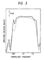
- Fig. 3 shows in solid line frequency characteristics of the filter according to the first embodiment shown in Fig. 1. Frequency characteristics of a filter constructed according to the conventional technique with the same number of comb electrodes is also shown in Fig. 3 by a dotted line for comparison purpose.
- the filter according to the embodiment shown in Fig. 1 is advantageous in insertion loss and flatness of frequency characteristics over the conventional filter. Further, although, according to the conventional technique, it is possible to reduce insertion loss by increasing the number of IDTs, it results in an increase of size of the filter. Therefore, this embodiment is compact since there is no need of increasing the IDTs.
- the IDTs are arranged symmetrically about the IDT 2-4.
- such symmetrical structure is not always necessary and the number of electrode fingers and inter-finger distance of all IDTs can be made different from each other. In such case, it is preferable to make the number of electrode fingers of one of the outermost IDTs smallest and the average value of inter-finger distance thereof largest.
- the number of the input side IDTs is 7 and that of the output side IDTs is 6 (referred to as 7 : 6), any other construction such as 8 : 7, 9 : 8, 6 : 7, 7 : 8 or 8 : 9, can be used with the same effect.
- Fig. 4 shows a second embodiment of the present invention.
- a pair of IDTs arrangements each similar to that shown in Fig. 1 are connected in series.
- Input side IDTs 7-1, 7-2, 7-3, 7-4, 7-5, 7-6 and 7-7 and intermediate IDTs 8-1, 8-2, 8-3, 8-4, 8-5 and 8-6 which correspond to the structure shown in Fig. 1 are arranged in a row and intermediate IDTs 9-1, 9-2, 9-3, 9-4, 9-5 and 9-6 and output side IDTs 10-1, 10-2, 10-3, 10-4, 10-5, 10-6 and 10-7 are also arranged in another row.
- the input side IDTs 7-1 to 7-7 are electrically connected to each other and to an input terminal 3.
- the intermediate IDTs 8-1 to 8-6 in the first row and the intermediate IDTs 9-1 to 9-6 in the second row are connected electrically in series with each other.
- the output side IDTs 10-1 to 10-7 are connected to each other and to an output terminal 5 electrically.
- the numbers of electrode fingers of the outermost IDTs 7-1 and 7-7 in the first row are smallest and average values of inter-finger distance thereof are largest compared with those of other IDTs in the same row. This is also the same for the IDTs in the second row. With such construction, frequency characteristics can be improved in transmitting energy from the first row to the second row. frequency characteristics can be improved in transmitting energy from the first row to the second row.
- all of the intermediate IDTs are connected in series through a junction electrically, it is possible to connect, for example, the intermediate IDT 8-1 in the first row directly to the intermediate IDT 9-1 in the second row, and similarly connect 8-2 to 9-2, 8-3 to 9-3, 8-4 to 9-4, 8-5 to 9-5 and 8-6 to 9-6. In such case, the freedom of design is further increased, resulting in a more precise design.
- Fig. 5 shows a third embodiment of the present invention in which the filter according to the present invention is applied to a portable telephone system.
- an antenna 21 is connected to a separator 22.
- the separator 22 has two output terminals one of which is connected to an input of a surface acoustic wave band-pass filter 23 constructed according to either the first or second embodiment of the present invention.
- the filter 23 has a center frequency f and an output terminal thereof is connected to a receiving terminal 25 of the telephone.
- a surface acoustic wave bandpass filter 24 constructed according to either the first or second embodiment of the present invention, having a center frequency f and connected to a transmitting terminal 26 is connected.
- the separator 22 comprises an isolator or a circulator and is used to separate transmitting direction of signal between receiving and transmission.
- a signal received by the antenna 21 is directed by the separator 22 to the surface acoustic wave band-pass filter 23 so that only necessary band thereof is transmitted through the filter 23 to the receiving terminal 25.
- a transmitting signal is supplied from the transmitting terminal 26 and tansmitted through the surface acoustic wave band-pass filter 24 to the separator 22 and, then transmitted from the antenna 21.
- the surface acoustic wave bandpass filter according to the present invention is compact in size and of low insertion loss. Therefore, by using it as a bandpass filter in a first stage on the antenna side of the portable telephone system, degradation of receiving sensitivity of the system is minimized. Further, since attenuation of transmission power is small, a smaller battery can be used. Since the size of the surface acoustic wave bandpass filter itself is small, it is possible to make the portable telephone system smaller.
- the separator 22 may be omitted depending upon a system specification.
- the surface acoustic wave bandpass filters 23 and 24 may act as branch devices.
- the present invention since amplitude and phase of electric signals are changed when the electric signal is converted into surface acoustic wave, when the latter propagates along the substrate and when it is converted into electric signal, it is possible to obtain a flat frequency characteristics. Further, since the number of electrode fingers of at least one of the outermost IDTs is smallest and the average value of inter-finger distance thereof is largest compared with other IDTs, it is possible to reduce insertion loss with relatively small number of electrode fingers. Further, since the number of IDTs to be used is small, it is possible to make it compact. Further, since the present surface acoustic wave bandpass filter is compact and of low insertion loss, it is possible to obtain a compact portable telephone system having high receiving sensitivity when the present filter is applied thereto.
Landscapes
- Physics & Mathematics (AREA)
- Acoustics & Sound (AREA)
- Surface Acoustic Wave Elements And Circuit Networks Thereof (AREA)
Applications Claiming Priority (2)
| Application Number | Priority Date | Filing Date | Title |
|---|---|---|---|
| JP1141014A JPH036913A (ja) | 1989-06-05 | 1989-06-05 | 弾性表面波フィルタ及びそれを用いた移動無線装置 |
| JP141014/89 | 1989-06-05 |
Publications (3)
| Publication Number | Publication Date |
|---|---|
| EP0401737A2 true EP0401737A2 (de) | 1990-12-12 |
| EP0401737A3 EP0401737A3 (de) | 1991-07-03 |
| EP0401737B1 EP0401737B1 (de) | 1997-10-01 |
Family
ID=15282190
Family Applications (1)
| Application Number | Title | Priority Date | Filing Date |
|---|---|---|---|
| EP90110598A Expired - Lifetime EP0401737B1 (de) | 1989-06-05 | 1990-06-05 | Akustischer Oberflächenwellenfilter und mobiles Telefon mit einem solchen Filter |
Country Status (4)
| Country | Link |
|---|---|
| US (1) | US5130681A (de) |
| EP (1) | EP0401737B1 (de) |
| JP (1) | JPH036913A (de) |
| DE (1) | DE69031512T2 (de) |
Cited By (5)
| Publication number | Priority date | Publication date | Assignee | Title |
|---|---|---|---|---|
| EP0543556A1 (de) * | 1991-11-18 | 1993-05-26 | Motorola, Inc. | Räumlich veränderliches akustisches Wellenfilter mit Mehrfachelektroden |
| EP0613258A1 (de) * | 1993-02-05 | 1994-08-31 | Ericsson Inc. | Leistungsregelungsvorrichtung für Duplexübertragung |
| EP0782255A3 (de) * | 1995-12-28 | 1998-01-14 | Murata Manufacturing Co., Ltd. | Akustisches Oberflächenwellenresonatorfilter mit longitudinaler Kopplung |
| EP1193869A3 (de) * | 1991-10-28 | 2002-08-07 | Fujitsu Limited | Akustisches Oberflächenwellenfilter |
| USRE40036E1 (en) | 1991-10-28 | 2008-01-29 | Fujitsu Limited | Surface acoustic wave filter |
Families Citing this family (7)
| Publication number | Priority date | Publication date | Assignee | Title |
|---|---|---|---|---|
| CA2062463C (en) * | 1991-03-29 | 1996-01-16 | Yoshio Satoh | Surface acoustic wave device for band-pass filter having small insertion loss and predetermined pass-band characteristics for broad band |
| EP0508325A1 (de) * | 1991-04-11 | 1992-10-14 | SIEMENS MATSUSHITA COMPONENTS GmbH & CO. KG | Reflektive Verzögerungsleitung in Oberflächenwellentechnik |
| EP0746095B1 (de) * | 1995-05-29 | 2007-02-14 | SANYO ELECTRIC Co., Ltd. | Akustischer Oberflächenwellenfilter |
| RU2099857C1 (ru) * | 1996-01-10 | 1997-12-20 | Наталья Федоровна Науменко | Высокочастотное устройство на поверхностных акустических волнах |
| JP3239064B2 (ja) * | 1996-05-28 | 2001-12-17 | 富士通株式会社 | 弾性表面波装置 |
| JPH10190394A (ja) * | 1996-12-25 | 1998-07-21 | Murata Mfg Co Ltd | 弾性表面波共振子フィルタ |
| US6097131A (en) * | 1998-03-19 | 2000-08-01 | Sawtek Inc. | Optimal cut for SAW devices on langatate |
Family Cites Families (13)
| Publication number | Priority date | Publication date | Assignee | Title |
|---|---|---|---|---|
| US3845419A (en) * | 1973-04-02 | 1974-10-29 | G Nudd | Acoustic surface wave device |
| JPS5310946A (en) * | 1976-07-17 | 1978-01-31 | Matsushita Electric Ind Co Ltd | Elastic surface wave filter |
| JPS56164826A (en) * | 1980-05-23 | 1981-12-18 | Dainippon Printing Co Ltd | Production of lenticular screen |
| JPS5740574U (de) * | 1980-08-20 | 1982-03-04 | ||
| JPS58154917A (ja) * | 1982-03-10 | 1983-09-14 | Hitachi Ltd | 弾性表面波バンドパスフイルタ |
| JPS60160719A (ja) * | 1984-02-01 | 1985-08-22 | Hitachi Ltd | 弾性表面波パワ−スプリツタ |
| JPS6170813A (ja) * | 1984-09-14 | 1986-04-11 | Hitachi Ltd | 弾性表面波分波器 |
| JPS61139015A (ja) * | 1984-12-11 | 1986-06-26 | Toshiba Corp | ガス絶縁計器用変成器の試験装置 |
| JPS62115A (ja) * | 1985-02-25 | 1987-01-06 | Oki Electric Ind Co Ltd | 弾性表面波フイルタ |
| JPS6382114A (ja) * | 1986-09-26 | 1988-04-12 | Alps Electric Co Ltd | 弾性表面波素子 |
| JPS63253712A (ja) * | 1987-04-10 | 1988-10-20 | Hitachi Ltd | 弾性表面波バンドパスフイルタ |
| JPS6423612A (en) * | 1987-07-20 | 1989-01-26 | Hitachi Ltd | Elastic surface wave device |
| JPS6482706A (en) * | 1987-09-25 | 1989-03-28 | Hitachi Ltd | Surface acoustic wave narrow-band filter |
-
1989
- 1989-06-05 JP JP1141014A patent/JPH036913A/ja active Pending
-
1990
- 1990-06-05 US US07/533,420 patent/US5130681A/en not_active Expired - Lifetime
- 1990-06-05 DE DE69031512T patent/DE69031512T2/de not_active Expired - Fee Related
- 1990-06-05 EP EP90110598A patent/EP0401737B1/de not_active Expired - Lifetime
Cited By (11)
| Publication number | Priority date | Publication date | Assignee | Title |
|---|---|---|---|---|
| EP1193869A3 (de) * | 1991-10-28 | 2002-08-07 | Fujitsu Limited | Akustisches Oberflächenwellenfilter |
| USRE40036E1 (en) | 1991-10-28 | 2008-01-29 | Fujitsu Limited | Surface acoustic wave filter |
| EP0543556A1 (de) * | 1991-11-18 | 1993-05-26 | Motorola, Inc. | Räumlich veränderliches akustisches Wellenfilter mit Mehrfachelektroden |
| US5309126A (en) * | 1991-11-18 | 1994-05-03 | Motorola, Inc. | Spatially varying multiple electrode acoustic wave filter and method therefor |
| US5463361A (en) * | 1991-11-18 | 1995-10-31 | Motorola, Inc. | Surface acoustic wave filter and method |
| EP0613258A1 (de) * | 1993-02-05 | 1994-08-31 | Ericsson Inc. | Leistungsregelungsvorrichtung für Duplexübertragung |
| US5487179A (en) * | 1993-02-05 | 1996-01-23 | Ericsson Ge Mobile Communications Inc. | Arrangement for duplex transmission having transmitter power control |
| CN1041480C (zh) * | 1993-02-05 | 1998-12-30 | 艾利森.Ge.流动通讯有限公司 | 用于双工传输的装置 |
| EP0782255A3 (de) * | 1995-12-28 | 1998-01-14 | Murata Manufacturing Co., Ltd. | Akustisches Oberflächenwellenresonatorfilter mit longitudinaler Kopplung |
| US5874868A (en) * | 1995-12-28 | 1999-02-23 | Murata Manufacturing, Co., Ltd. | Longitudinally coupled surface acoustic wave resonator filter having different distances between transducers |
| CN1070660C (zh) * | 1995-12-28 | 2001-09-05 | 株式会社村田制作所 | 纵向耦合型表面声共振器波滤波器 |
Also Published As
| Publication number | Publication date |
|---|---|
| JPH036913A (ja) | 1991-01-14 |
| EP0401737B1 (de) | 1997-10-01 |
| DE69031512T2 (de) | 1998-01-29 |
| EP0401737A3 (de) | 1991-07-03 |
| US5130681A (en) | 1992-07-14 |
| DE69031512D1 (de) | 1997-11-06 |
Similar Documents
| Publication | Publication Date | Title |
|---|---|---|
| US5694096A (en) | Surface acoustic wave filter | |
| US6104260A (en) | Surface acoustic wave filter with first and second filter tracks and balanced or unbalanced terminals | |
| EP0746095B1 (de) | Akustischer Oberflächenwellenfilter | |
| EP0401737B1 (de) | Akustischer Oberflächenwellenfilter und mobiles Telefon mit einem solchen Filter | |
| EP1263137B1 (de) | Akustisches Oberflächenwellenfilter, symmetrisches Filter und Kommunikationsgerät | |
| CN1131478A (zh) | 声表面波装置 | |
| US5463361A (en) | Surface acoustic wave filter and method | |
| US6326864B1 (en) | Surface acoustic wave filter, duplexer and communications device with specific series resonator multiple anti-resonant point placement | |
| CN100355204C (zh) | 弹性表面波装置、通信装置 | |
| EP1630956B1 (de) | Oberflächenwellen-Bauelement | |
| EP0316836B1 (de) | Akustische Oberflächenwellenanordnung | |
| US6801100B2 (en) | Inter-digital transducer, surface acoustic wave filter and communication apparatus using the same | |
| US5610566A (en) | Saw filter with a coupled saw impedance element | |
| EP0506249B1 (de) | Akustische Oberflächenwellenanordnung für Bandpassfilter mit geringer Einfügungsdämpfung und vorbestimmter Bandpasskennlinie für Breitbandigkeit | |
| EP0782256B1 (de) | Akustisches Oberflächenwellenresonatorfilter | |
| EP1276236B1 (de) | Interdigitaler Wandler, akustisches Oberflächenwellenfilter und diesen Wandler verwendendes Kommunikationsgerät | |
| US5087901A (en) | Surface acoustic wave band-pass filter with different phase weighted transducers | |
| US6147574A (en) | Unidirectional surface acoustic wave transducer and transversal-type saw filter having the same | |
| JP3419949B2 (ja) | 縦結合二重モードsawフィルタ | |
| JP3315913B2 (ja) | 弾性表面波フィルタ | |
| JP3131573B2 (ja) | 弾性表面波フィルタ | |
| US6310524B1 (en) | Edge reflection type longitudinally coupled saw resonator filter | |
| JP4454703B2 (ja) | 弾性表面波フィルタ | |
| JPH01135113A (ja) | 弾性表面波装置 | |
| JP2000183682A (ja) | 二重モードsawフィルタ |
Legal Events
| Date | Code | Title | Description |
|---|---|---|---|
| PUAI | Public reference made under article 153(3) epc to a published international application that has entered the european phase |
Free format text: ORIGINAL CODE: 0009012 |
|
| 17P | Request for examination filed |
Effective date: 19900605 |
|
| AK | Designated contracting states |
Kind code of ref document: A2 Designated state(s): DE FR GB |
|
| PUAL | Search report despatched |
Free format text: ORIGINAL CODE: 0009013 |
|
| AK | Designated contracting states |
Kind code of ref document: A3 Designated state(s): DE FR GB |
|
| 17Q | First examination report despatched |
Effective date: 19931217 |
|
| GRAG | Despatch of communication of intention to grant |
Free format text: ORIGINAL CODE: EPIDOS AGRA |
|
| GRAH | Despatch of communication of intention to grant a patent |
Free format text: ORIGINAL CODE: EPIDOS IGRA |
|
| GRAH | Despatch of communication of intention to grant a patent |
Free format text: ORIGINAL CODE: EPIDOS IGRA |
|
| GRAH | Despatch of communication of intention to grant a patent |
Free format text: ORIGINAL CODE: EPIDOS IGRA |
|
| GRAA | (expected) grant |
Free format text: ORIGINAL CODE: 0009210 |
|
| AK | Designated contracting states |
Kind code of ref document: B1 Designated state(s): DE FR GB |
|
| REF | Corresponds to: |
Ref document number: 69031512 Country of ref document: DE Date of ref document: 19971106 |
|
| ET | Fr: translation filed | ||
| PLBE | No opposition filed within time limit |
Free format text: ORIGINAL CODE: 0009261 |
|
| STAA | Information on the status of an ep patent application or granted ep patent |
Free format text: STATUS: NO OPPOSITION FILED WITHIN TIME LIMIT |
|
| 26N | No opposition filed | ||
| REG | Reference to a national code |
Ref country code: GB Ref legal event code: IF02 |
|
| PGFP | Annual fee paid to national office [announced via postgrant information from national office to epo] |
Ref country code: FR Payment date: 20060602 Year of fee payment: 17 Ref country code: DE Payment date: 20060602 Year of fee payment: 17 |
|
| PGFP | Annual fee paid to national office [announced via postgrant information from national office to epo] |
Ref country code: GB Payment date: 20060613 Year of fee payment: 17 |
|
| GBPC | Gb: european patent ceased through non-payment of renewal fee |
Effective date: 20070605 |
|
| REG | Reference to a national code |
Ref country code: FR Ref legal event code: ST Effective date: 20080229 |
|
| PG25 | Lapsed in a contracting state [announced via postgrant information from national office to epo] |
Ref country code: DE Free format text: LAPSE BECAUSE OF NON-PAYMENT OF DUE FEES Effective date: 20080101 |
|
| PG25 | Lapsed in a contracting state [announced via postgrant information from national office to epo] |
Ref country code: GB Free format text: LAPSE BECAUSE OF NON-PAYMENT OF DUE FEES Effective date: 20070605 |
|
| PG25 | Lapsed in a contracting state [announced via postgrant information from national office to epo] |
Ref country code: FR Free format text: LAPSE BECAUSE OF NON-PAYMENT OF DUE FEES Effective date: 20070702 |