EP1276236B1 - Interdigitaler Wandler, akustisches Oberflächenwellenfilter und diesen Wandler verwendendes Kommunikationsgerät - Google Patents
Interdigitaler Wandler, akustisches Oberflächenwellenfilter und diesen Wandler verwendendes Kommunikationsgerät Download PDFInfo
- Publication number
- EP1276236B1 EP1276236B1 EP20020015358 EP02015358A EP1276236B1 EP 1276236 B1 EP1276236 B1 EP 1276236B1 EP 20020015358 EP20020015358 EP 20020015358 EP 02015358 A EP02015358 A EP 02015358A EP 1276236 B1 EP1276236 B1 EP 1276236B1
- Authority
- EP
- European Patent Office
- Prior art keywords
- electrode
- surface acoustic
- acoustic wave
- idt
- idt electrode
- Prior art date
- Legal status (The legal status is an assumption and is not a legal conclusion. Google has not performed a legal analysis and makes no representation as to the accuracy of the status listed.)
- Expired - Lifetime
Links
- 238000010897 surface acoustic wave method Methods 0.000 title claims description 225
- 238000004891 communication Methods 0.000 title claims description 20
- 239000000758 substrate Substances 0.000 claims description 49
- 230000005540 biological transmission Effects 0.000 claims description 20
- 238000010586 diagram Methods 0.000 description 17
- 230000006866 deterioration Effects 0.000 description 10
- 230000008878 coupling Effects 0.000 description 7
- 238000010168 coupling process Methods 0.000 description 7
- 238000005859 coupling reaction Methods 0.000 description 7
- 238000000034 method Methods 0.000 description 5
- 238000005516 engineering process Methods 0.000 description 4
- 230000001902 propagating effect Effects 0.000 description 4
- 125000004122 cyclic group Chemical group 0.000 description 3
- 230000000694 effects Effects 0.000 description 3
- 238000003780 insertion Methods 0.000 description 3
- 230000037431 insertion Effects 0.000 description 3
- 239000013078 crystal Substances 0.000 description 2
- 229910011131 Li2B4O7 Inorganic materials 0.000 description 1
- 229910003327 LiNbO3 Inorganic materials 0.000 description 1
- 229910012463 LiTaO3 Inorganic materials 0.000 description 1
- XAGFODPZIPBFFR-UHFFFAOYSA-N aluminium Chemical compound [Al] XAGFODPZIPBFFR-UHFFFAOYSA-N 0.000 description 1
- 229910052782 aluminium Inorganic materials 0.000 description 1
- 230000015556 catabolic process Effects 0.000 description 1
- 238000006243 chemical reaction Methods 0.000 description 1
- 230000007423 decrease Effects 0.000 description 1
- 238000006731 degradation reaction Methods 0.000 description 1
- 230000001419 dependent effect Effects 0.000 description 1
- 238000013461 design Methods 0.000 description 1
- 238000011161 development Methods 0.000 description 1
- 239000007772 electrode material Substances 0.000 description 1
- 238000011156 evaluation Methods 0.000 description 1
- PCHJSUWPFVWCPO-UHFFFAOYSA-N gold Chemical compound [Au] PCHJSUWPFVWCPO-UHFFFAOYSA-N 0.000 description 1
- 239000010931 gold Substances 0.000 description 1
- 229910052737 gold Inorganic materials 0.000 description 1
- 238000002955 isolation Methods 0.000 description 1
- 238000010295 mobile communication Methods 0.000 description 1
- 238000012545 processing Methods 0.000 description 1
- 239000004065 semiconductor Substances 0.000 description 1
- 230000035945 sensitivity Effects 0.000 description 1
Images








Classifications
-
- H—ELECTRICITY
- H03—ELECTRONIC CIRCUITRY
- H03H—IMPEDANCE NETWORKS, e.g. RESONANT CIRCUITS; RESONATORS
- H03H9/00—Networks comprising electromechanical or electro-acoustic elements; Electromechanical resonators
- H03H9/46—Filters
- H03H9/64—Filters using surface acoustic waves
- H03H9/6423—Means for obtaining a particular transfer characteristic
- H03H9/6433—Coupled resonator filters
- H03H9/644—Coupled resonator filters having two acoustic tracks
- H03H9/6456—Coupled resonator filters having two acoustic tracks being electrically coupled
- H03H9/6459—Coupled resonator filters having two acoustic tracks being electrically coupled via one connecting electrode
- H03H9/6463—Coupled resonator filters having two acoustic tracks being electrically coupled via one connecting electrode the tracks being electrically cascaded
-
- H—ELECTRICITY
- H03—ELECTRONIC CIRCUITRY
- H03H—IMPEDANCE NETWORKS, e.g. RESONANT CIRCUITS; RESONATORS
- H03H9/00—Networks comprising electromechanical or electro-acoustic elements; Electromechanical resonators
- H03H9/0023—Networks for transforming balanced signals into unbalanced signals and vice versa, e.g. baluns, or networks having balanced input and output
- H03H9/0028—Networks for transforming balanced signals into unbalanced signals and vice versa, e.g. baluns, or networks having balanced input and output using surface acoustic wave devices
- H03H9/0033—Networks for transforming balanced signals into unbalanced signals and vice versa, e.g. baluns, or networks having balanced input and output using surface acoustic wave devices having one acoustic track only
- H03H9/0038—Networks for transforming balanced signals into unbalanced signals and vice versa, e.g. baluns, or networks having balanced input and output using surface acoustic wave devices having one acoustic track only the balanced terminals being on the same side of the track
-
- H—ELECTRICITY
- H03—ELECTRONIC CIRCUITRY
- H03H—IMPEDANCE NETWORKS, e.g. RESONANT CIRCUITS; RESONATORS
- H03H9/00—Networks comprising electromechanical or electro-acoustic elements; Electromechanical resonators
- H03H9/0023—Networks for transforming balanced signals into unbalanced signals and vice versa, e.g. baluns, or networks having balanced input and output
- H03H9/0028—Networks for transforming balanced signals into unbalanced signals and vice versa, e.g. baluns, or networks having balanced input and output using surface acoustic wave devices
- H03H9/0033—Networks for transforming balanced signals into unbalanced signals and vice versa, e.g. baluns, or networks having balanced input and output using surface acoustic wave devices having one acoustic track only
- H03H9/0042—Networks for transforming balanced signals into unbalanced signals and vice versa, e.g. baluns, or networks having balanced input and output using surface acoustic wave devices having one acoustic track only the balanced terminals being on opposite sides of the track
-
- H—ELECTRICITY
- H03—ELECTRONIC CIRCUITRY
- H03H—IMPEDANCE NETWORKS, e.g. RESONANT CIRCUITS; RESONATORS
- H03H9/00—Networks comprising electromechanical or electro-acoustic elements; Electromechanical resonators
- H03H9/0023—Networks for transforming balanced signals into unbalanced signals and vice versa, e.g. baluns, or networks having balanced input and output
- H03H9/0028—Networks for transforming balanced signals into unbalanced signals and vice versa, e.g. baluns, or networks having balanced input and output using surface acoustic wave devices
- H03H9/0047—Networks for transforming balanced signals into unbalanced signals and vice versa, e.g. baluns, or networks having balanced input and output using surface acoustic wave devices having two acoustic tracks
- H03H9/0052—Networks for transforming balanced signals into unbalanced signals and vice versa, e.g. baluns, or networks having balanced input and output using surface acoustic wave devices having two acoustic tracks being electrically cascaded
- H03H9/0061—Networks for transforming balanced signals into unbalanced signals and vice versa, e.g. baluns, or networks having balanced input and output using surface acoustic wave devices having two acoustic tracks being electrically cascaded the balanced terminals being on opposite sides of the tracks
-
- H—ELECTRICITY
- H03—ELECTRONIC CIRCUITRY
- H03H—IMPEDANCE NETWORKS, e.g. RESONANT CIRCUITS; RESONATORS
- H03H9/00—Networks comprising electromechanical or electro-acoustic elements; Electromechanical resonators
- H03H9/02—Details
- H03H9/02535—Details of surface acoustic wave devices
- H03H9/02637—Details concerning reflective or coupling arrays
- H03H9/02685—Grating lines having particular arrangements
- H03H9/02763—Left and right side electrically coupled reflectors
-
- H—ELECTRICITY
- H03—ELECTRONIC CIRCUITRY
- H03H—IMPEDANCE NETWORKS, e.g. RESONANT CIRCUITS; RESONATORS
- H03H9/00—Networks comprising electromechanical or electro-acoustic elements; Electromechanical resonators
- H03H9/02—Details
- H03H9/125—Driving means, e.g. electrodes, coils
- H03H9/145—Driving means, e.g. electrodes, coils for networks using surface acoustic waves
- H03H9/14538—Formation
-
- H—ELECTRICITY
- H03—ELECTRONIC CIRCUITRY
- H03H—IMPEDANCE NETWORKS, e.g. RESONANT CIRCUITS; RESONATORS
- H03H9/00—Networks comprising electromechanical or electro-acoustic elements; Electromechanical resonators
- H03H9/46—Filters
- H03H9/64—Filters using surface acoustic waves
- H03H9/6423—Means for obtaining a particular transfer characteristic
- H03H9/6433—Coupled resonator filters
- H03H9/6479—Capacitively coupled SAW resonator filters
Definitions
- the present invention relates to an inter-digital transducer provided with a balanced type terminal, a longitudinally coupled mode type surface acoustic wave filter and a communication apparatus using the same.
- SAW surface acoustic wave
- IDT inter-digital transducer
- the SAW has been practically utilized for delay line for radar, band-pass filter for television receiver, etc.
- the SAW is extensively used as RF and IF stage filters for receiving and transmitting circuits in radio-communication apparatus.
- transversal SAW filter and two kinds of longitudinally coupled mode coupled and transverse mode coupled type SAW filters.
- the transversal SAW filter has small group delay variation characteristic, but it has large insertion loss and large element size.
- the mode coupled type SAW filter presents steep attenuation characteristic, shows small insertion loss, and is small in element size, but its group delay variation characteristic is inferior to that of transversal type SAW filter.
- the longitudinally coupled mode type SAW filter is characterized by having relatively wide pass band
- the transverse mode type SAW filter is characterized by having very narrow pass band characteristic.
- balancing of semiconductor parts such as IC has advanced in recent years in order to reduce noise characteristics and balancing is also required for surface acoustic wave filters used for the RF stage. Furthermore, from the standpoint of impedance matching with ICs placed before and after, control over impedance of surface acoustic wave is required in recent years.
- a surface acoustic wave filter used for the RF stage will be explained first as a first conventional technology.
- a longitudinally coupled mode type surface acoustic wave filter having a conventional balanced type input/output terminals will be explained below.
- FIG. A12 shows a configuration of a longitudinally coupled mode type surface acoustic wave filter having conventional balanced type input/output terminals.
- the surface acoustic wave filter is constructed by forming input IDT electrodes 3002a and 3002b, reflector electrodes 3003a and 3003b and output IDT electrode 3004 on a piezoelectric substrate 3001.
- the electrode fingers of the input IDT electrodes 3002a and 3002b on the same side are connected to an input terminal S and the other fingers are grounded.
- the upper electrode digit of the output IDT electrode 3004 is connected to one output terminal T1 and the lower electrode digit of the output IDT electrode 3004 is connected to the other output terminal T2.
- FIG. B24 is a block diagram showing a transversal mode coupled resonator type surface acoustic wave filter according to a conventional technology.
- reference numeral 241 denote a single crystal piezoelectric substrate and by forming an electrode pattern on this piezoelectric substrate 241, it is possible to excite surface acoustic wave.
- Reference numeral 242a denotes an IDT electrode formed on the piezoelectric substrate 241 and reflector electrodes 242b and 242c are placed on both sides of the IDT electrode forming thereby an energy-containment type surface acoustic wave resonator.
- an IDT electrode 243a, reflector electrodes 243b and 243c form a similar surface acoustic wave resonator on the piezoelectric substrate 241. These two resonators are placed close to each other and a surface acoustic wave filter is formed by generating acoustic coupling between these resonators.
- two kinds of surface acoustic wave mode frequencies to be excited on the piezoelectric substrate are determined according to the aperture length of the electrode fingers of the IDT electrodes and the distance between the two surface acoustic wave resonators placed close to each other and the passing bandwidth of the filter is determined.
- the surface acoustic wave filters explained in the first and second conventional technologies are required to have impedance matching with IC elements in the preceding and following stages, and since the input/output impedance of the above-described conventional filters is dependent on the number of pairs of electrode fingers included in the IDT electrodes and aperture length closely associated with the filter characteristic, there is a problem that it is difficult to attain a desired filter characteristic and a desired impedance value simultaneously.
- the present invention has as its object to provide an inter-digital transducer, a surface acoustic wave filter having an optimal balancing and controlling input/output impedance and communication apparatus using it.
- EP 0 809 357 discloses a surface acoustic wave filter and multistage surface acoustic wave filter with a balanced type input and output constitution with low insertion loss, and with a wide pass band width, in which a desired input and output impedance can be obtained.
- a lower electrode resistance of the IDT electrodes is obtained by providing two surface acoustic resonators close to each other, such that directions of propagation of the surface acoustic waves are parallel and acoustically coupled, and providing leading out electrodes from at least two places of the inside bus bar.
- the 1st invention of the present invention is an inter-digital transducer comprising:
- the 2nd implementation of the present invention is the inter-digital transducer according to 2nd invention, wherein the ratio in the number of electrode fingers among said plurality of divisional IDT electrodes is adjusted beforehand so as to have a predetermined impedance value.
- the 3rd implementation of the present invention is the inter-digital transducer according to 3rd invention, wherein said plurality of divisional IDT electrodes is placed in an same/reverse phase relationship so that charges of the divisional IDT electrodes do not cancel out each other.
- the 4th implementation of the present invention is the inter-digital transducer according to 1st implementation of the invention, wherein said second divisional IDT electrode is placed in in same phase relationship between said first divisional IDT electrode and said third divisional IDT electrode, the part of said upper bus bar electrode corresponding to said first divisional IDT electrode and the part of said upper bus bar electrode corresponding to said second divisional IDT electrode are connected to one end of said balanced type terminal, and the part of said lower bus bar electrode corresponding to said second divisional IDT electrode and the part of said lower bus bar electrode corresponding to said third divisional IDT electrode are connected to the other end of said balanced type terminal.
- the 6th implementation of the present invention is the inter-digital transducer according to 4th invention, wherein said plurality of divisional IDT electrodes is constructed of first, second, third and fourth divisional IDT electrodes.
- the 7th implementation of the present invention is the inter-digital transducer according to 16th invention, wherein said plurality of divisional IDT electrodes is placed in order of said first, second, third and fourth divisional IDT electrodes, the part of said upper bus bar electrode corresponding to said first divisional IDT electrode, the part of said upper bus bar electrode corresponding to said third divisional IDT electrode and the part of said upper bus bar electrode corresponding to said fourth divisional IDT electrode are connected, and the part of said lower bus bar electrode corresponding to said first divisional IDT electrode, the part of said lower bus bar electrode corresponding to said second divisional IDT electrode and the part of said lower bus bar electrode corresponding to said fourth divisional IDT electrode are connected.
- the 8th implementation of the present invention is the inter-digital transducer according to 18th invention, wherein of said plurality of electrode fingers, substantially all adjacent pairs of electrode fingers are in an same phase relationship and substantially all of the plurality of electrode fingers is connected so that respective charges do not cancel out each other.
- the 9th implementation of the present invention is the inter-digital transducer according to 17th invention, wherein the part of said upper bus bar electrode corresponding to said second IDT electrode is grounded and the part of said lower bus bar electrode corresponding to said third IDT electrode is grounded.
- the 10st implementation of the present invention is the inter-digital transducer according to 17th invention, wherein the part of said upper bus bar electrode corresponding to said second IDT electrode is connected to the part of said lower bus bar electrode corresponding to said third IDT electrode.
- the 11nd implementation of the present invention is the inter-digital transducer according to 21st invention, wherein said "connection" means that, of adjacent electrode fingers of said second divisional IDT electrode and said third divisional IDT electrode, said second divisional IDT electrode digit is connected to both the part of said upper electrode corresponding to said second divisional IDT electrode and the part of said lower electrode corresponding to said third divisional IDT electrode, and of adjacent electrode fingers said third divisional IDT electrode digit is connected to both the part of said lower electrode corresponding to said third divisional IDTelectrode and the part of said upper electrode corresponding to said second divisional IDT electrode.
- the 12th implementation of present invention is the surface acoustic wave filter according to 24th invention, wherein said three IDT electrodes are first, second and third IDT electrodes, said second IDT electrode and said third IDT electrode are placed on both sides of said first IDT electrode respectively, said reflector electrodes are placed opposite said first IDT electrode of said second IDT electrode and opposite said first IDT electrode of said third IDT electrode respectively, and said first IDT electrode is the IDT electrode of said inter-digital transducer.
- the 26th invention of the present invention is the surface acoustic wave filter according to 25th invnetion, wherein the upper bus bar electrode of said second IDT electrode is connected to an unbalanced type terminal and the lower bus bar electrode is grounded and the lower bus bar electrode of said third IDT electrode is connected to said unbalanced type terminal and the upper bus bar electrode is grounded.
- the 14th implementation of the present invention is a surface acoustic wave filter comprising:
- the 15th implementation of the present invention is the surface acoustic wave filter according to 14th implementation of the invention, wherein said plurality means 2, saidplurality of acoustic wave filters area first surface acoustic wave filter and a second surface acoustic wave filter, said first and second surface acoustic wave filters each comprise at least three IDT electrodes, said first and second surface acoustic wave filters are connected in cascade form, said first and second surface acoustic wave filters are connected at two points using at least two IDT electrodes, and the phase of one signal of said IDT electrode is opposite the phase of the other signal of said IDT electrode.
- the 16th implementation of the present invention is a surface acoustic wave filter comprising:
- the 17th implementation of the present invention is a surface acoustic wave filter comprising:
- the 18th implementation of the present invention is a communication apparatus comprising:
- IDT electrode inter-digital transducer
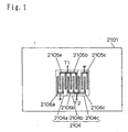
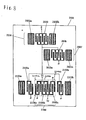
- FIG. 1 shows an IDT electrode 2104 according to Embodiment 1 of the present invention.
- the IDT electrode 2104 is placed on a piezoelectric substrate 2101 and is an electrode that converts a surface acoustic wave propagating on the piezoelectric substrate to an electric signal and converts an electric signal to a surface acoustic wave propagating on the piezoelectric substrate.
- the IDT electrode 2104 is divided into three portions, first, second and third divisional IDT electrodes 2104a, 2104b and 2104c and constructed by connecting the three groups of divisional IDT electrodes 2104a, 2104b and 2104c.
- first divisional IDT electrode 2104a, second divisional IDT electrode 2104b and third divisional IDT electrode 2104c are placed in such a way as to be same phase with one another.
- upper electrodes 2105a and 2105b of the first and second divisional IDT electrodes 2104a and 2104b are electrically connected and also connected to one end T1 of a balanced type output terminal.
- lower electrodes 2106b and 2106c of the second and third divisional IDT electrodes 2104b and 2104c are electrically connected and also connected to the other end T2 of the balanced type output terminal.
- the lower electrode 2106a of the first divisional IDT electrode 2104a and the upper electrode 2105c of the third divisional IDT electrode 2104c are grounded.
- the IDT electrode 2104 converts a surface acoustic wave propagating on the piezoelectric substrate to an electric signal and outputs to the balanced type output terminals T1 and T2.
- the IDT electrode 2104 converts an electric signal input from T1 or T2 to a surface acoustic wave propagating on the piezoelectric substrate 2101.
- the IDT electrode 2104 of this embodiment can convert an electric signal to a surface acoustic wave and convert a surface acoustic wave to an electric signal.
- This embodiment is characterized in that when the IDT electrode 2104 of this embodiment is divided into the first divisional IDT electrode 2104a, second divisional IDT electrode 2104b and third divisional IDT electrode 2104c and the ratio of the number of electrode fingers between the first, second and third divisional IDT electrodes 2104a, 2104b and 2104c is changed, impedance values at T1 and T2 change, whereas the frequency characteristic of the IDT electrode 2104 does not mostly change.
- the IDT electrode 2104 of this embodiment has an excellent feature of being capable of controlling impedance.
- FIG. 2 illustrates an IDT electrode 183a known from the prior art which differs from the IDT electrode 2104 in the layout of electrode fingers, etc.
- the IDT electrode 183a is divided into three portions of first, second, third divisional IDT electrodes 184a, 184b and 184c and is constructed by connecting the three groups of the divisional IDT electrodes 184a, 184b and 184c.
- the IDT electrode 183a in FIG. 2 also has an excellent feature of being capable of controlling impedance in the same way as the IDT electrode 2104 in FIG. 1 .
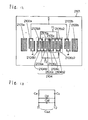
- FIG. 3 is a schematic view of a surface acoustic wave filter according to Embodiment A1.
- reference numeral 2101 denotes a piezoelectric substrate and it is possible to excite a surface acoustic wave by constructing electrode patterns crossing in strip-line form with a cyclic structure on this piezoelectric substrate 2101.
- a longitudinally coupledmode type surface acoustic wave filter comprising input IDT electrodes 2102a and 2102b, reflector electrodes 2103a and 2103b and an output IDT electrode 2104 is formed on the piezoelectric substrate 2101.
- Each IDT electrode consists of a pair of mutually facing comb-like electrodes and each comb-like electrode consists of electrode fingers and electrodes (upper electrode and lower electrode) from which these electrode fingers are led out.
- the upper electrodes of the input IDT electrodes 2102a and 2102b are connected to an input terminal S and the lower electrodes of the input IDT electrodes 2102a and 2102b are grounded.
- the output IDT electrode 2104 is divided into three portions, first, second and third divisional IDT electrodes 2104a,2104b and 2104c and constructed by connecting the three groups of divisional IDT electrodes 2104a, 2104b and 2104c.
- the first divisional IDT electrode 2104a, second divisional IDT electrode 2104b and third divisional IDT electrode 2104c are placed in such a way as to be same phase with one another.
- upper electrodes 2105a and 2105b of the first and second divisional IDT electrodes 2104a and 2104b are electrically connected and also connected to one end T1 of a balanced type output terminal.
- lower electrodes 2106b and 2106c of the second and third divisional IDT electrodes 2104b and 2104c are electrically connected and also connected to the other end T2 of the balanced type output terminal. Furthermore, the lower electrode 2106a of the first divisional IDT electrodes 2104a and the lower electrode 2106c of the third divisional IDT electrodes 2104c are grounded.
- the two adjacent electrode fingers are in an same phase relationship means that the two adjacent electrode fingers are in such a connection relationship that one of the two electrode fingers is connected to the upper electrode and extends downward and the other electrode digit is connected to the lower electrode and extends upward.
- the charge of the upper electrode is different from that of the lower electrode.
- the pitch between the two adjacent electrode fingers (center distance) is 1/2 ⁇ ⁇ .
- the above-described pitch between the electrode fingers may also be (m+1/2) ⁇ ⁇ .
- the above-described pitch between the electrode fingers is (m+1/2) ⁇ ⁇
- the above-described. same phase relationship is completely opposite the same phase relationship described above. That is, that the two adjacent electrode fingers are in an same phase relationship means that the pitch between the electrode fingers is (m+1) ⁇ ⁇ and both electrode fingers are connected to the upper electrode or that the pitch between the electrode fingers is (m+1) ⁇ ⁇ and both electrode fingers are connected to the lower electrode.
- the upper electrodes 2105a and 2105b of the first and second divisional IDT electrodes 2104a and 2104b are electrically connected and also connected to one end T1 of the balanced type output terminal and the lower electrodes 2106b and 2106c of the second and third divisional IDT electrodes 2104b and 2104c are electrically connected and also connected to the other end T2 of the balanced-type output terminal.
- the one end T1 and the other end T2 of the balanced type output terminal are connected to the upper and lower sides opposite each other, in the case where both of the above-described two adjacent electrode fingers in an same phase relationship are led out from the upper electrode or lower electrode both of which are connected to the balanced type terminals, their respective positive and negative charges are reversed.
- all electrode fingers are assumed to be substantially same phase, and this means that some electrode fingers maybe placed at different locations due to withdrawing, etc. and that any configuration is acceptable if the electrode fingers as a whole at least allow surface acoustic waves to be excited.
- Embodiment A1 This applies not only to Embodiment A1 but also to Embodiment 1 and Embodiment A1 and subsequent embodiments.
- this embodiment has such a configuration that the adj acent electrode fingers of the input IDT electrode 2102a and divisional IDT electrode 2104a are led out from the lower electrodes in the same direction and the adjacent electrode fingers of the input IDT electrode 2102b and divisional IDT electrode 2104c are led out from the upper electrodes in the same direction, but this positional relationship may change depending on the number of electrode fingers,etc. and any positional relationship different from this positional relationship may also be adopted if it at least allows surface acoustic waves to be excited without being cancelled out:
- the input IDT electrodes 2102a and 2102b and output IDT electrode 2104 are examples of the IDT electrodes of the present invention
- the respective upper electrodes and lower electrodes of input IDT electrodes 2102a and 2102b and output IDT electrode 2104 are examples of the upper bus bar electrodes and lower bus bar electrodes of the present invention.
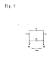
- FIG. 4 is a capacitance equivalent circuit diagram of Embodiment A1.
- Reference characters Ca, Cb and Cc denote capacitances of the first, second and third divisional IDT electrodes 2104a, 2104b and 2104c respectively and a total capacitance of Ca, Cb and Cc constitutes a total capacitance Cout of the output IDT electrode 2104 and is expressed in the following expression. That is, the first divisional IDT electrode 2104a and third divisional IDT electrode 2104c are connected in series, while the second divisional IDT electrode 2104b is connected in parallel with the first divisional IDT electrode 2104a and third divisional IDT electrode 2104c.
- the capacitances of the IDT electrodes are dominant in impedance of the surface acoustic wave filter, it is possible to control the total capacitance Cout of the input IDT electrode 2104 and control impedance by changing the number of pairs Na, Nb and Nc of the divisional IDT electrodes 2104a, 2104b and 2104c.
- impedance can be controlled as follows. First, the number of pairs N and pitch of electrode fingers, etc. of the input IDT electrode 2104 are determined in the design stage to obtain a desired filter characteristic. Then, while the numbers of pairs N of the input IDT electrode 2104 is fixed, the numbers of pairs Na, Nb and Nc of the divisional IDT electrodes 2104a, 2104b and 2104c are changed. In this way, it is possible to obtain impedance of the surface acoustic wave filter from Mathematical expression 3. Therefore, it is possible to determine Na, Nb and Nc using Mathematical expression 3 so that the desired impedance is obtained.
- the filter characteristic of the surface acoustic wave filter does not change significantly when the ratio between Na, Nb and Nc is changed while N is fixed.
- using the surface acoustic wave filter of this embodiment makes it possible to obtain a desired filter characteristic and control impedance so that desired impedance can be obtained.
- a longitudinally coupled mode type surface acoustic wave filter is obtained whose impedance is controllable by changing the ratio of the number of pairs among the divisional IDT electrodes.
- FIG. 5 shows a schematic view of a surface acoustic wave filter having a pad electrode.
- a pad electrode 2301 on the input side is connected to the input IDT electrodes 2102a and 2102b via routing electrodes 2302a and 2302b.
- first and second pad electrode 2303a and 2303b on the output side are connected to the upper side and lower side of the output electrode.
- the first output side pad electrode 2303a is connected to the upper bus bar electrode 2105a of the first divisional IDT electrode 2104a and the upper bus bar electrode 2105b of the second divisional IDT electrode and the second output side pad electrode 2303b is connected to the lower bus bar electrode 2106b of the second divisional IDT electrode 2104b and the lower bus bar electrode 2106c of the third divisional IDT electrode 2104c.
- connecting with the respective pad electrodes can be performed using wires or directly through face down mounting.
- the divisional IDT electrode 2104a and divisional IDT electrode 2104c have the same number of electrode fingers and the adjacent electrode fingers of the input IDT electrode 2102a and divisional IDT electrode 2104a are led out from the lower bus bar electrodes in the same direction and the adjacent electrode fingers of the input IDT electrode 2102b and divisional IDT electrode 2104c are led out from the upper bus bar electrodes in the same direction.
- the adjacent electrode fingers of the input IDT electrode 2102b and divisional IDT electrode 2104c are led out from the upper bus bar electrodes in the same direction.
- the characteristic as the surface acoustic wave filter can be obtained likewise as far as those electrodes are in such a positional relationship that surface acoustic waves are excited without canceling out each other.
- first and third divisional IDT electrodes 2104a and 2104c have the same number of divided pairs and the divisional IDT electrode 2104b has the same number of upper and lower electrode fingers, the same number of IDT electrode digit pairs are connected to both balanced type output terminals. Adopting such a configuration provides a surface acoustic wave filter with excellent balancing.
- This embodiment has described the case where the respective upper bus bar electrodes of the input IDT electrodes 2102a and 2102b are connected to the input terminal S and the respective lower bus bar electrodes of the input IDT electrodes 2102a and 2102b are grounded but this embodiment is not limited to this.
- the upper bus bar electrode of the input IDT electrode 2102a and the lower bus bar electrode of the input IDT electrode 2102b may also be connected to the input terminal S and the lower bus bar electrode of the input IDT electrode 2102a and the upper bus bar electrode of the input IDT electrode 2102b may be grounded.
- the lower bus bar electrode of the input IDT electrode 2102a and the upper bus bar electrode of the input IDT electrode 2102b may also be connected to the input terminal S and the upper bus bar electrode of the input IDT electrode 2102a and the lower bus bar electrode of the input IDT electrode 2102b may be grounded. That is, the signal route from the input terminal S is connected structurally upside down. Furthermore, the electrode fingers of the input IDT electrodes 2102a and 2102b are placed in such a way that surface acoustic waves do not cancel out each other.
- the adjacent electrode fingers of the input IDT electrode 2102a and divisional IDT electrode 2104a are led out from the upper bus bar electrode and lower bus bar electrode in directions crossing each other respectively and the adjacent electrode fingers of the input IDT electrode 2102b and divisional IDT electrode 2104c are led out from the upper bus bar electrode in the same directions, but this positional relationship varies depending on the number of electrode fingers, etc. and any positional relationship different from this positional relationship may also be used if it at least allows surface acoustic waves to be excited without canceling out each other.
- Adopting such a configuration suppresses the deterioration of balancing due to spatial coupling between wiring lead out from the input IDT electrodes 2102a and 2102b connected to the input terminal S and wiring lead out from the IDT electrode 2104 connected to the output terminals T1 and T2 making it possible to obtain a surface acoustic filter having optimal balancing.
- this embodiment has explained that the divisional IDT electrodes are on the output side, but the divisional IDT electrodes can also be on the input side. In this case, the divisional IDT electrodes can control impedance on the input side.
- this embodiment has explained that the output IDT electrode 2104 is divided into divisional IDT electrodes 2104a, 2104b and 2104c, but it is also possible to divide the input IDT electrode 2102a and/or input IDT electrode 2102b into divisional IDT electrodes to form a balanced type terminal configuration. In this case, both the input side and output side constitute balanced type terminals, making it possible to control impedance.
- this embodiment has explained that the output IDT electrode 2104 is divided into three portions, divisional IDT electrodes 2104a, 2104b and 2104c, but it is also possible to divide the output IDT electrode 2104 into 4, 5 or more divisional IDT electrodes.
- FIG. 13 shows a case where the output IDT electrode 2104 is divided into two divisional IDT electrodes.
- the surface acoustic wave filter comprises a total of 3 IDT electrodes, that is, one output IDT electrode 2104 and two input IDT electrodes 2102a and 2102b, but this embodiment is not limited to this.
- the surface acoustic wave filter of this embodiment may also be constructed of two, five, seven or any number of IDT electrodes.
- the method of grounding the upper electrode 2105c of the divisional IDT electrode 2104c and the lower electrode 2106a of the divisional IDT electrode 2104a it is also possible to provide independent grounding apart from the grounding electrodes of the input IDT electrodes 2102a and 2102b or instead of actually grounding the upper electrode 2105c of the divisional IDT electrode 2104c and the lower electrode 2106a of the divisional IDT electrode 2104a, it is also possible to electrically connect them thereby providing virtual grounding.
- the case of virtual grounding is equivalent to a configuration of the capacitance equivalent circuit in FIG. A2 without grounding. In these cases, it is possible to suppress deterioration of the characteristic due to routing of the signal from GND.
- the surface acoustic wave filter of this embodiment also assumes the role of conversion between balance and unbalance. That is, the surface acoustic wave filter of this embodiment can also function as a balun.
- the surface acoustic wave filter of this embodiment can not only have a balanced type terminal but also control input/output impedance of the surface acoustic wave filter.
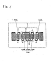
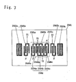
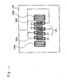
- FIG. 7 is a schematic view of the surface acoustic wave filter according to Embodiment A2.
- reference numeral 2501 denotes a piezoelectric substrate and it is possible to excite a surface acoustic wave by constructing comb-like electrode patterns crossing in strip-line form with a cyclic structure on this piezoelectric substrate 2501.
- a longitudinally coupled mode type surface acoustic wave filter comprising input IDT electrodes 2502a and 2502b, reflector electrodes 2503a and 2503b and an output IDT electrode 2504 is formed on the piezoelectric substrate 2501.
- the upper electrode of the input IDT electrode 2502a is connected to one input terminal S1 and the upper electrode of the input IDT electrode 2502b is connected to the other input terminal S2 and the lower electrodes of the input IDT electrodes 2502a and 2502b are grounded.
- This embodiment A2 is different from Embodiment A1 in that the input IDT electrodes 2502a and 2502b are of a balanced type.
- S1 and S2 constitute balanced type terminals and the signals input from S1 and S2 to the input IDT electrodes 2502a and 2502b have phases opposite each other. Furthermore, the adjacent electrode fingers of the input IDT electrode 2502a and the divisional IDT electrode 2504a are led out from the lower bus bar electrode and upper bus bar electrode in directions crossing each other and the adjacent electrode fingers of the input IDT electrode 2502b and the divisional IDT electrode 2504c are led out from the upper bus bar electrodes in the same directions.
- This positional relationship varies depending on the number of electrode fingers and a positional relationship different from this positional relationship may also be used as far as it at least allows surface acoustic waves to be excited without canceling out each other.
- the output IDT electrode 2504 is constructed of three groups, first, second and third divisional IDT electrodes 2504a, 2504b and 2504c.
- the first divisional IDT electrode 2504a, second divisional IDT electrode 2504b and third divisional IDT electrode 2504c are placed same phase with one another.
- the upper electrodes 2505a and 2505b of the first and second divisional IDT electrodes 2504a and 2504b are electrically connected and also connected to one terminal T1 of the balance type output terminal.
- the lower electrodes 2506b and 2506c of the second and third divisional IDT electrodes 2504b and 2504c are electrically connected and also connected to the other end T2 of the balanced type output terminal.
- the lower electrode 2506a of the first divisional IDT electrode 2504a and the lower electrode 2506c of the third divisional IDT electrode 2504c are grounded.
- Embodiment A2 configured as shown above is different from Embodiment A1 only in the balanced type input terminals and the locations of the input IDT electrodes, and the same in the method of division, operation and effects of the output IDT electrodes.
- signals to the input IDT electrodes 2502a and 2502b in the above configuration have phases opposite each other, it is possible to suppress characteristic deterioration due to spatial coupling and reduce deterioration of balancing due to direct coupling between the input IDT 2502a and 2502b and output IDT 2504.
- This embodiment assumes that the upper electrodes 2505a and 2505b of the first and second divisional IDT electrodes 2504a and 2504b are electrically connected, but the respective upper electrodes may also be united into one common upper electrode. Furthermore, this embodiment also assumes that the lower electrodes 2506b and 2506c of the second and third divisional IDT electrodes 2504b and 2504c are electrically connected, but the respective upper electrodes may also be united into one common lower electrode.
- the method of grounding the upper electrode 2505c of the divisional IDT electrode 2504c and the lower electrode 2506a of the divisional IDT electrode 2504a it is also possible to independently ground them apart from the grounding electrodes of the input IDT electrodes 2502a and 2502b or electrically connect the upper electrode 2505c of the divisional IDT electrode 2504c and the lower electrode 2506a of the divisional IDT electrode 2504a.
- FIG. 8 is a schematic view of the surface acoustic wave filter according to Embodiment A3.
- reference numeral 2601 denotes a piezoelectric substrate and it is possible to excite a surface acoustic wave by constructing electrode patterns crossing in strip-line form with a cyclic structure on this piezoelectric substrate 2601.
- a longitudinally coupled mode type surface acoustic wave filter comprising input IDT electrodes 2102a and 2102b, reflector electrodes 2103a and 2103b and an output IDT electrode 2104 is formed on the piezoelectric substrate 2601, and this embodiment in this configuration is the same as the surface acoustic wave filter shown in Embodiment A1 .
- the upper electrodes of the input IDT electrodes 2102a and 2102b are connected to an input terminal S via a surface acoustic wave resonator 2604 connected in series and formed of reflector electrodes 2602a, 2602b and an IDT electrode 2603. Furthermore, between the surface acoustic wave resonator 2604 and the upper electrodes of the input IDT electrodes 2102a and 2102b, a surface acoustic wave resonator 2607 formed of reflector electrodes 2605a and 2605b and an IDT electrode 2606 is connected in parallel and one end of the surface acoustic wave resonator 2607 is grounded.
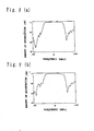
- FIG. 9 shows a passing characteristic of the above-described surface acoustic wave filter.
- FIG. 9a shows a configuration before the division, that is, a passing characteristic when the output IDT electrode 3004 of the conventional configuration shown in FIG . 12 is used instead of the output IDT electrode 2104 shown in Fig. 6 .
- the system is designed assuming that the number of pairs of output IDTs is 18 and output impedance is 50 ⁇ .
- FIG. 9b of shows a characteristic assuming that the numbers of pairs of the first, second and third divisional IDT electrodes 2104a, 2104b. and 2104c are 6 respectively and output impedance is 100 ⁇ .
- FIG. 9b show the results of evaluation with 50 ⁇ and 100 ⁇ respectively as the condition of impedance on the output side.
- the system is designed to have a total capacitance of the output IDT electrodes 1/2 and impedance of 100 ⁇ twice those before the division.
- FIG. 9b shows that output impedance is changed while the waveform of the surface acoustic wave filter using the divisional IDT electrode maintains the passing characteristic almost equivalent to that before the division in FIG. 9a .
- This embodiment places the surface acoustic wave resonator 2607 in series between the input IDT electrodes 2102a and 2102b and input terminal S and in parallel with the surface acoustic wave resonator 2604, but it is also possible to place a longitudinally coupledmode type surface acoustic wave filter as shown in FIG. 10 and form a surface acoustic wave filter in two-stage configuration.
- reference numeral 2801 denotes a piezoelectric substrate
- a first-stage surface acoustic wave filter 2802 is constructed of an input IDT electrode 2803, reflector electrodes 2804a and 2804b and output IDT electrodes 2805a and 2805b.
- the upper electrode of the input IDT electrode 2803 is connected to the input terminal S and the lower electrode is grounded.
- the upper electrode of the output IDT electrode 2805a is grounded and the lower electrode is connected to the input IDT electrode 2102a of a second-stage surface acoustic wave filter 2806.
- the upper electrode of the output IDT electrode 2805b is grounded and the lower electrode is connected to the input IDT electrode 2102b of the second-stage surface acoustic wave filter 2806.
- the second-stage surface acoustic wave filter 2806 has the same configuration as that in FIG. A1 shown in Embodiment A1.
- the adjacent electrode fingers of the input IDT electrode 2803 and output IDT electrode 2805a of the first-stage surface acoustic wave filter 2802 are led out from the lower bus bar electrodes in the same direction and the adjacent electrode fingers of the input IDT electrode 2803 and output IDT electrode 2805c are led out from the lower bus bar electrodes in the same direction.
- same phase signals are transmitted from the output IDT electrodes 2805a and 2805b of the first-stage surface acoustic wave filter 2801 to the second-stage surface acoustic wave filter 2806.
- this embodiment assumes that the adj acent electrode fingers of the input IDT electrode 2803 and output IDT electrode 2805a of the first-stage surface acoustic wave filter 2802 are led out from the lower electrodes in the same direction and the adjacent electrode fingers of the input IDT electrode 2803 and output IDT electrode 2805b are led out from the lower bus bar electrodes in the same direction, but even if the adjacent electrode fingers of the input IDT electrode 2805 and output IDT electrode 2805a are led out from the respective electrodes in directions crossing each other and the adjacent electrode fingers of the input IDT electrode 2803 and output IDT electrode 2805b are led out from the respective electrodes in directions crossing each other, the same characteristic as the surface acoustic wave filter can be obtained likewise as far as the output IDT electrodes 2805a and 2805b are in such a phase relationship that surface acoustic waves do not cancel out each other.
- This positional relationship varies depending on the number of electrode fingers, etc. and a positional relationship different from this positional relationship may also be used as far as it provides at least a phase relationship whereby surface acoustic waves are excited without canceling out each other.
- this embodiment places the surface acoustic wave resonator 2607 in series between the input IDT electrodes 2102a and 2102b and input terminal S, and in parallel with the surface acoustic wave resonator 2604, but it is also possible to place a longitudinally coupled mode type surface acoustic wave filter as shown in FIG. 11 to form a surface acoustic wave filter in a two-stage configuration.
- reference numeral 2901 denotes a piezoelectric substrate
- a first-stage surface acoustic wave filter 2902 is constructed of an input IDT electrode 2903, reflector electrodes 2904a and 2904b and output IDT electrodes 2905a and 2905b.
- the upper electrode of the input IDT electrode 2903 is connected to the input terminal S and the lower electrode is grounded.
- the upper electrode of the output IDT electrode 2905a is grounded and the lower electrode is connected to the input IDT electrode 2502a of a second-stage surface acoustic wave filter 2906.
- the upper electrode of the output IDT electrode 2905b is grounded and the lower electrode is connected to the input IDT electrode 2502b of the second-stage surface acoustic wave filter 2906.
- the second-stage surface acoustic wave filter 2906 has the same configuration as that in Embodiment A2.
- the output IDT electrodes 2905a and 2905b of the first-stage surface acoustic wave filter 2902 are in a positional relationship having phases opposite each other. That is, reverse phase signals are transmitted from the output IDT electrodes 2905a and 2905b of the first-stage surface acoustic wave filter 2902 to the second-stage surface acoustic wave filter 2906.
- the above-described configuration makes the signals from the output IDT electrodes 2905a and 2905b of the first-stage surface acoustic wave filter 2902 opposite each other, making it possible to suppress characteristic degradation due to spatial coupling in the route up to the second-stage surface acoustic wave filter and reduce balancing deterioration due to direct coupling between the input IDT electrodes 2502a and 2502b and the output IDT 2504 of the second-stage surface acoustic wave filter 2906.
- this embodiment can control impedance on both the input side and output side.
- the surface acoustic wave filter of the present invention can control impedance and using this surface acoustic wave filter for a mobile unit communication apparatus facilitates impedance matching of IC, etc. and makes it possible to realize a high performance communication apparatus.
- this embodiment has an advantage of providing a longitudinally coupled mode type surface acoustic wave filter with balanced type terminals, capable of controlling input/output impedance.
- a communication apparatus using the surface acoustic wave filter of the present invention for a transmission circuit and/or reception circuit also belongs to the present invention.
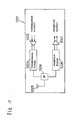
- FIG. A17 is a block diagram of communication apparatus 1001 using the surface acoustic wave filter or balanced type filter of the present invention.
- a transmission signal output from a transmission circuit is passed through a transmission amplifier 1002, a transmission filter 1003 and a switch 1004 and sent out from an antenna 1005.
- a reception signal received by antenna 1005 is passed through the switch 1004, a reception filter 1006 and a reception amplifier 1007 and input to a reception circuit.
- the transmission filter 1003 has a configuration having an unbalanced - balanced type terminal. Furthermore, since the reception amplifier 1007 is of a balanced type and the switch 1004 is of an unbalanced type, the reception filter 1006 has a configuration having an unbalanced - balanced type terminal.
- Applying the surface acoustic wave filter or balanced type filter of this embodiment of the present invention to the transmission filter 1003 or reception filter 1006 of the communication apparatus 1001 can suppress deterioration in modulation accuracy during transmission due to deterioration of the balance characteristic and suppress deterioration in the sensitivity during reception due to deterioration of the balance characteristic, making it possible to realize a high performance communication apparatus.
- Embodiment A6 has been described assuming that the transmission filter 1003 and reception filter 1006 are of an unbalanced - balanced type, but when the switch 1004 is of a balanced type, it is possible to provide balanced type transmission filter 1003 and balanced type reception filter 1006.
- the switch 1004 is of a balanced type and the transmission amplifier 1002 or reception amplifier 1007 is of an unbalanced type, it is possible to obtain similar effects by switching between the balanced type and unbalanced type input/output terminals of the transmission filter 1003 or reception filter 1006.
- this embodiment has described the case where the switch 1004 is used as the means for switching between transmission and reception at communication apparatus 1001, but a duplexer can be used instead.
- the surface acoustic wave filter of this embodiment allows impedance matching without adding an inductance between the balanced type terminals as the matching circuit. Therefore, applying the surface acoustic wave filter of this embodiment to a mobile unit communication apparatus further makes it possible to reduce the size of the mobile unit communication apparatus.
- the piezoelectric substrate in the present invention use of an ST cut crystal having excellent temperature characteristics is preferable, but there may be used as substrates LiTaO 3 , LiNbO 3 , Li 2 B 4 O 7 , La 3 Ga 3 SiO 14 and the like.
- As an electrode material use of relatively low density aluminum whose film thickness control is easy is preferable, but use of gold electrode is also possible.
- the present invention is applicable to resonators using not only the SAW described above but also SSBW(Surface Skimming Balk Wave) which is one of the SAW or Pseudo surface waves, and the like.
- the present invention can provide a surface acoustic wave filter and communication apparatus with optimal balancing and capable of controlling input/output impedance.
- the present invention can also provide an inter-digital transducer, surface acoustic wave filter and communication apparatus having desired input/output impedance.
Landscapes
- Physics & Mathematics (AREA)
- Acoustics & Sound (AREA)
- Surface Acoustic Wave Elements And Circuit Networks Thereof (AREA)
Claims (18)
- Akustisches Oberflächenwellenfilter, umfassend:ein piezoelektrisches Substrat (2101);eine Vielzahl interdigitaler Wandlerelektroden, im folgenden IDT-Elektroden genannt (2102a, 2102b, 2104), die ein Paar bestehend aus einer oberen Sammelschienenelektrode und einer unteren Sammelschienenelektrode haben, die einander zugewandt auf dem piezoelektrischen Substrat angeordnet sind, sowie eine Vielzahl von Elektrodenfingern, die entweder aus der oberen Sammelschienenelektrode oder der unteren Sammelschienenelektrode zu der anderen Sammelschienenelektrode geleitet sind;eine Vielzahl Reflektorelektroden (2103a, 2103b), die auf dem piezoelektrischen Substrat angeordnet sind, undeinen symmetrischen Anschluss (T1, T2), der auf dem piezoelektrischen Substrat angeordnet ist,wobei das akustische Oberflächenwellenfilter ein akustisches Oberflächenwellenfilter vom Typ eines in Längsrichtung gekoppelten Modus' ist, bei dem die Vielzahl von IDT-Elektroden und die Vielzahl von Reflektorelektroden jeweils in den Ausbreitungsrichtungen akustischer Oberflächenwellen angeordnet sind,dadurch gekennzeichnet, dasswenigstens eine aus der Vielzahl von IDT-Elektroden aus wenigstens drei Teil-IDT-Elektroden (2104a, 2104b, 2104c) aufgebaut ist und diese Teil-IDT-Elektroden mit dem symmetrischen Anschluss verbunden sind undwenigstens zwei der Teil-IDT-Elektroden (2104b, 2104c) in Reihe geschaltet sind und wenigstens eine (2104a) der verbleibenden Teil-IDT-Elektroden mit den wenigstens zwei Teil-IDT-Elektroden parallel geschaltet ist.
- Akustisches Oberflächenwellenfilter nach Anspruch 1, bei dem das Verhältnis der Zahl der Elektrodenfinger innerhalb der Vielzahl von Teil-IDT-Elektroden (2104a, 2104b, 2104c) im Voraus eingestellt ist, um so einen vorbestimmten Impedanzwert zu haben.
- Akustisches Oberflächenwellenfilter nach Anspruch 2, bei dem die Vielzahl von Teil-IDT-Elektroden (2104a, 2104b, 2104c) in einer gleichphasigen/gegenphasigen Beziehung angeordnet ist, so dass sich Ladungen der Teil-IDT-Elektroden nicht gegenseitig aufheben.
- Akustisches Oberflächenwellenfilter nach Anspruch 1,
bei dem die zweite Teil-IDT-Elektrode (2104b) in einer gleichphasigen Beziehung zwischen der ersten Teil-IDT-Elektrode (2104a) und der dritten Teil-IDT-Elektrode (2104c) angeordnet ist,
der Teil der oberen Sammelschienenelektrode, der der ersten Teil-IDT-Elektrode entspricht, und der Teil der oberen Sammelschienenelektrode, der der zweiten Teil-IDT-Elektrode entspricht, mit einem Ende (T1) des symmetrischen Anschlusses verbunden sind und der Teil der unteren Sammelschienenelektrode, der der zweiten Teil-IDT-Elektrode entspricht, sowie der Teil der unteren Sammelschienenelektrode, der der dritten Teil-IDT-Elektrode entspricht, mit dem anderen Ende (T2) des symmetrischen Anschlusses verbunden sind und
der Teil der unteren Sammelschienenelektrode, der der ersten Teil-IDT-Elektrode entspricht, mit dem Teil der oberen Sammelschienenelektrode verbunden ist, der der dritten Teil-IDT-Elektrode entspricht. - Akustisches Oberflächenwellenfilter nach Anspruch 1, bei dem die zweite Teil-IDT-Elektrode (2104b) zwischen der ersten Teil-IDT-Elektrode (2104a) und der dritten Teil-IDT-Elektrode (2104c) angeordnet ist, der Teil der unteren Sammelschienenelektrode, der der ersten Teil-IDT-Elektrode entspricht, mit dem Teil der oberen Sammelschienenelektrode verbunden ist, der der zweiten Teil-IDT-Elektrode entspricht, und der Teil der unteren Sammelschienenelektrode, der der zweiten Teil-IDT-Elektrode entspricht, mit dem Teil der unteren Sammelschienenelektrode verbunden ist, der der dritten Teil-IDT-Elektrode entspricht und
die obere Sammelschienenelektrode der ersten Teil-IDT-Elektrode mit der unteren Sammelschienenelektrode der dritten Teil-IDT-Elektrode verbunden ist. - Akustisches Oberflächenwellenfilter nach Anspruch 3, bei dem die Vielzahl von Teil-IDT-Elektroden aus ersten (2104b1), zweiten (2104a), dritten (2104c) und vierten (2104b2) Teil-IDT-Elektroden aufgebaut ist.
- Akustisches Oberflächenwellenfilter nach Anspruch 6,
bei dem die Vielzahl von Teil-IDT-Elektroden in der Reihenfolge von erster (2104b1), zweiter (2104a), dritter (2104c) und vierter (2104b2) Teil-IDT-Elektroden angeordnet ist,
der Teil der oberen Sammelschienenelektrode, der der ersten Teil-IDT-Elektrode entspricht, der Teil der oberen Sammelschienenelektrode, der der dritten Teil-IDT-Elektrode entspricht, und der Teil der oberen Sammelschienenelektrode, der der vierten Teil-IDT-Elektrode entspricht, in gleichphasiger Beziehung verbunden sind, und
der Teil der unteren Sammelschienenelektrode, der der ersten Teil-IDT-Elektrode entspricht, der Teil der unteren Sammelschienenelektrode, der der zweiten Teil-IDT-Elektrode entspricht, und der Teil der unteren Sammelschienenelektrode, der der vierten Teil-IDT-Elektrode entspricht, miteinander verbunden sind. - Akustisches Oberflächenwellenfilter nach Anspruch 7,
bei dem aus der Vielzahl von Elektrodenfingern im wesentlichen sämtliche benachbarten Paare von Elektrodenfingern in phasengleicher Beziehung sind und im wesentlichen sämtliche der Vielzahl von Elektrodenfingern derart verbunden sind, dass sich entsprechende Ladungen nicht gegenseitig aufheben. - Akustisches Oberflächenwellenfilter nach Anspruch 7,
bei dem der Teil der oberen Sammelschienenelektrode, der der zweiten IDT-Elektrode (2104a) entspricht, geerdet ist und der Teil der unteren Sammelschienenelektrode, der der dritten IDT-Elektrode (2104c) entspricht, geerdet ist. - Akustisches Oberflächenwellenfilter nach Anspruch 7,
bei dem der Teil der oberen Sammelschienenelektrode, der der zweiten IDT-Elektrode (2104a) entspricht, mit dem Teil der unteren Sammelschienenelektrode verbunden ist, der der dritten IDT-Elektrode (2104c) entspricht. - Akustisches Oberflächenwellenfilter nach Anspruch 10,
bei dem "Verbindung" bedeutet, dass von benachbarten Elektrodenfingern der zweiten Teil-IDT-Elektrode (2104a) und der dritten Teil-IDT-Elektrode (2104c) der zweite Teil-IDT-Elektrodenfinger sowohl mit dem Teil der oberen Elektrode, der der zweiten Teil-IDT-Elektrode entspricht, als auch mit dem Teil der unteren Elektrode verbunden ist, der der dritten Teil-IDT-Elektrode entspricht, und
von benachbarten Elektrodenfingern der dritte Teil-IDT-Elektrodenfinger sowohl mit dem Teil der unteren Elektrode, der der dritten Teil-IDT-Elektrode (2104c) entspricht, als auch mit dem Teil der oberen Elektrode verbunden ist, der der zweiten Teil-IDT-Elektrode (2104a) entspricht. - Akustisches Oberflächenwellenfilter nach Anspruch 1,
bei dem die drei IDT-Elektroden erste, zweite und dritte IDT-Elektroden sind,
die zweite IDT-Elektrode (2102a) und die dritte IDT-Elektrode (2102b) jeweils auf beiden Seiten der ersten IDT-Elektrode (2104) angeordnet sind,
die Reflektorelektroden (2103a), (2103b) gegenüber der ersten IDT-Elektrode der zweiten IDT-Elektrode bzw. gegenüber der ersten IDT-Elektrode der dritten IDT-Elektrode angeordnet sind und
die erste IDT-Elektrode die IDT-Elektrode des interdigitalen Wandlers ist. - Akustisches Oberflächenwellenfilter nach Anspruch 12, bei dem die obere Sammelschienenelektrode der zweiten IDT-Elektrode (2102a) mit einem asymmetrischen Anschluss (S) verbunden ist, die untere Sammelschienenelektrode geerdet ist, die untere Sammelschienenelektrode (2102b) der dritten IDT-Elektrode mit dem asymmetrischen Anschluss verbunden ist und die obere Sammelschienenelektrode geerdet ist.
- Akustisches Oberflächenwellenfilter umfassend:ein piezoelektrisches Substrat (2101) undeine Vielzahl akustischer Oberflächenwellenfilter vom Typ eines in Längsrichtung gekoppelten Modus', die eine Vielzahl von IDT-Elektroden (2102a, 2102b, 2104) und eine Vielzahl von Reflektorelektroden (2103a, 2103b) haben, die auf dem piezoelektrischen Substrat angeordnet sind,wobei die Vielzahl von akustischen Oberflächenwellenfiltern in mehreren Stufen verbunden sind,von der Vielzahl akustischer Oberflächenwellenfilter wenigstens die akustischen Oberflächenwellenfilter auf der Eingangsseite und/oder die akustischen Oberflächenwellenfilter auf der Ausgangsseite die akustischen Oberflächenwellenfilter nach Anspruch 1 sind, unddie piezoelektrischen Substrate wenigstens der akustischen Oberflächenwellenfilter auf der Eingangsseite und/oder der akustischen Oberflächenwellenfilter auf der Ausgangseite aus der Vielzahl von akustischen Oberflächenwellenfiltern die piezoelektrischen Substrate der akustischen Oberflächenwellenfilter nach Anspruch 1 sind.
- Akustisches Oberflächenwellenfilter nach Anspruch 14,
bei dem die Vielzahl 2 bedeutet,
die Vielzahl akustischer Oberflächenwellenfilter ein erstes akustisches Oberflächenwellenfilter und ein zweites akustisches Oberflächenwellenfilter sind,
die ersten und zweiten akustischen Oberflächenwellenfilter jeweils wenigstens drei IDT-Elektroden (2102a, 2102b, 2104) umfassen,
die ersten und zweiten akustischen Oberflächenwellenfilter kaskadenartig verbunden sind,
die ersten und zweiten akustischen Oberflächenwellenfilter an zwei Punkten mit Hilfe wenigstens zweier IDT-Elektroden verbunden sind und
die Phase eines Signals der IDT-Elektrode der Phase des anderen Signals der IDT-Elektrode entgegengesetzt ist. - Akustisches Oberflächenwellenfilter nach Anspruch 1, bei dem die Zahl von IDT-Elektroden gleich zwei ist und
der Teil der oberen Sammelschienenelektrode der IDT-Elektrode, der der ersten Teil-IDT-Elektrode (2104a) entspricht und/oder der Teil der oberen Sammelschienenelektrode der IDT-Elektrode, der der zweiten Teil-IDT-Elektrode (2104b) entspricht, mit dem einem Ende (T1) des symmetrischen Anschlusses verbunden ist/sind und
der Teil der unteren Sammelschienenelektrode der IDT-Elektrode, der der zweiten Teil-IDT-Elektrode (2104b) entspricht, und/oder der Teil der unteren Sammelschienenelektrode der IDT-Elektrode, der der dritten Teil-IDT-Elektrode (2104c) entspricht, mit dem anderen Ende T2 des symmetrischen Anschlusses verbunden ist/sind. - Akustisches Oberflächenwellenfilter nach Anspruch 1, bei dem die Zahl von IDT-Elektroden gleich fünf ist und
der Teil der oberen Sammelschienenelektrode der IDT-Elektrode, der der ersten Teil-IDT-Elektrode (2104a) entspricht und/oder der Teil der oberen Sammelschienenelektrode der IDT-Elektrode, der der zweiten Teil-IDT-Elektrode (2104b) entspricht, mit dem einen Ende (T1) eines symmetrischen Anschlusses verbunden ist/sind und
der Teil der unteren Sammelschienenelektrode der IDT-Elektrode, der der zweiten Teil-IDT-Elektrode (2104b) entspricht, und/oder der Teil der unteren Sammelschienenelektrode der IDT-Elektrode, der der dritten Teil-IDT-Elektrode (2104c) entspricht, mit dem anderen Ende (T2) des symmetrischen Anschlusses verbunden ist/sind. - Kommunikationsgerät, umfassend:einen Sendeschaltkreis, der Sendewellen ausgibt, undeinen Empfangsschaltkreis, der Empfangswellen empfängt,wobei das akustische Oberflächenwellenfilter, das für den Sendeschaltkreis und/oder den Empfangsschaltkreis verwendet wird, das akustische Oberflächenwellenfilter nach Anspruch 1 ist.
Applications Claiming Priority (4)
| Application Number | Priority Date | Filing Date | Title |
|---|---|---|---|
| JP2001211345 | 2001-07-11 | ||
| JP2001211345 | 2001-07-11 | ||
| JP2002149802 | 2002-05-23 | ||
| JP2002149802A JP3564114B2 (ja) | 2001-07-11 | 2002-05-23 | 弾性表面波フィルタ、及びそれを用いた通信機器 |
Publications (3)
| Publication Number | Publication Date |
|---|---|
| EP1276236A2 EP1276236A2 (de) | 2003-01-15 |
| EP1276236A3 EP1276236A3 (de) | 2008-11-12 |
| EP1276236B1 true EP1276236B1 (de) | 2013-09-11 |
Family
ID=26618554
Family Applications (1)
| Application Number | Title | Priority Date | Filing Date |
|---|---|---|---|
| EP20020015358 Expired - Lifetime EP1276236B1 (de) | 2001-07-11 | 2002-07-10 | Interdigitaler Wandler, akustisches Oberflächenwellenfilter und diesen Wandler verwendendes Kommunikationsgerät |
Country Status (2)
| Country | Link |
|---|---|
| EP (1) | EP1276236B1 (de) |
| JP (1) | JP3564114B2 (de) |
Cited By (1)
| Publication number | Priority date | Publication date | Assignee | Title |
|---|---|---|---|---|
| WO2025218886A1 (en) * | 2024-04-17 | 2025-10-23 | Huawei Technologies Co., Ltd. | An acoustic resonator device, an electronic apparatus and a manufacturing method |
Families Citing this family (8)
| Publication number | Priority date | Publication date | Assignee | Title |
|---|---|---|---|---|
| JP4562517B2 (ja) * | 2004-12-27 | 2010-10-13 | 京セラ株式会社 | 弾性表面波素子および通信装置 |
| JPWO2006134959A1 (ja) | 2005-06-17 | 2009-01-08 | 松下電器産業株式会社 | 多重モード薄膜弾性波共振器フィルタ |
| EP2017961A4 (de) | 2006-05-08 | 2011-02-16 | Murata Manufacturing Co | Elastische wellenfiltervorrichtung und duplexer |
| DE112012000675B4 (de) | 2011-02-04 | 2017-09-21 | Murata Manufacturing Co., Ltd. | Filtermodul |
| WO2012105373A1 (ja) | 2011-02-04 | 2012-08-09 | 株式会社村田製作所 | デュプレクサモジュール |
| JP5753115B2 (ja) * | 2012-03-12 | 2015-07-22 | Jx日鉱日石金属株式会社 | プリント配線板用圧延銅箔 |
| RU2633658C2 (ru) * | 2016-03-09 | 2017-10-16 | Акционерное общество "Научно-производственное предприятие "Радар ммс" | Резонатор на поверхностных акустических волнах |
| CN116318042A (zh) * | 2023-02-27 | 2023-06-23 | 中电科技德清华莹电子有限公司 | 一种无介质桥的声表面波滤波器 |
Family Cites Families (3)
| Publication number | Priority date | Publication date | Assignee | Title |
|---|---|---|---|---|
| EP0921636B1 (de) * | 1996-05-23 | 2007-04-04 | Matsushita Electric Industrial Co., Ltd. | Akustisches Oberflächenwellenfilter und mehrstufiges akustisches Oberflächenwellenfilter |
| JP3315644B2 (ja) * | 1998-05-14 | 2002-08-19 | 富士通株式会社 | 弾性表面波素子 |
| DE19938748B4 (de) * | 1999-08-16 | 2007-02-01 | Epcos Ag | Dualmode-Oberflächenwellen-Filter mit verbesserter Symmetrie und erhöhter Sperrdämpfung |
-
2002
- 2002-05-23 JP JP2002149802A patent/JP3564114B2/ja not_active Expired - Lifetime
- 2002-07-10 EP EP20020015358 patent/EP1276236B1/de not_active Expired - Lifetime
Cited By (1)
| Publication number | Priority date | Publication date | Assignee | Title |
|---|---|---|---|---|
| WO2025218886A1 (en) * | 2024-04-17 | 2025-10-23 | Huawei Technologies Co., Ltd. | An acoustic resonator device, an electronic apparatus and a manufacturing method |
Also Published As
| Publication number | Publication date |
|---|---|
| EP1276236A3 (de) | 2008-11-12 |
| JP2003092526A (ja) | 2003-03-28 |
| EP1276236A2 (de) | 2003-01-15 |
| JP3564114B2 (ja) | 2004-09-08 |
Similar Documents
| Publication | Publication Date | Title |
|---|---|---|
| EP1126605B1 (de) | Oberflächenwellenfilteranordnung | |
| US7902940B2 (en) | Duplexer | |
| EP0809357B1 (de) | Akustischer Oberflächenwellenfilter und mehrstufiger akustischer Oberflächenwellenfilter | |
| US7283016B2 (en) | Balanced acoustic wave filter and acoustic wave filter | |
| US6483402B2 (en) | Surface acoustic wave device | |
| EP0924857A2 (de) | Akustisches Oberfächenwellenfilter | |
| EP1263137B1 (de) | Akustisches Oberflächenwellenfilter, symmetrisches Filter und Kommunikationsgerät | |
| EP2254244B1 (de) | Symmetrierfilter und Duplexer | |
| JP3534080B2 (ja) | 弾性表面波フィルタ装置 | |
| JP2001326557A (ja) | 弾性表面波装置 | |
| US20100026417A1 (en) | Surface Acoustic Wave Filter | |
| US7425879B2 (en) | Surface acoustic wave filter apparatus and branching filter | |
| US6816036B2 (en) | Surface acoustic wave filter and communication apparatus | |
| JP2002314371A (ja) | 弾性表面波フィルタ装置、通信装置 | |
| EP0981857B1 (de) | Oberflächenwellen balun resonatorfilter | |
| US6801100B2 (en) | Inter-digital transducer, surface acoustic wave filter and communication apparatus using the same | |
| JP2003069383A (ja) | 弾性表面波フィルタ | |
| US6756867B2 (en) | Surface acoustic wave filter and communication apparatus | |
| JP3564114B2 (ja) | 弾性表面波フィルタ、及びそれを用いた通信機器 | |
| US6348845B2 (en) | Surface acoustic wave filter and multistage surface acoustic wave filter | |
| JP2003092526A5 (de) | ||
| JP3999977B2 (ja) | 弾性表面波フィルタ装置 | |
| WO2018212025A1 (ja) | マルチプレクサ、送信装置および受信装置 |
Legal Events
| Date | Code | Title | Description |
|---|---|---|---|
| PUAI | Public reference made under article 153(3) epc to a published international application that has entered the european phase |
Free format text: ORIGINAL CODE: 0009012 |
|
| AK | Designated contracting states |
Kind code of ref document: A2 Designated state(s): AT BE BG CH CY CZ DE DK EE ES FI FR GB GR IE IT LI LU MC NL PT SE SK TR |
|
| AX | Request for extension of the european patent |
Free format text: AL;LT;LV;MK;RO;SI |
|
| PUAL | Search report despatched |
Free format text: ORIGINAL CODE: 0009013 |
|
| AK | Designated contracting states |
Kind code of ref document: A3 Designated state(s): AT BE BG CH CY CZ DE DK EE ES FI FR GB GR IE IT LI LU MC NL PT SE SK TR |
|
| AX | Request for extension of the european patent |
Extension state: AL LT LV MK RO SI |
|
| RAP1 | Party data changed (applicant data changed or rights of an application transferred) |
Owner name: PANASONIC CORPORATION |
|
| 17P | Request for examination filed |
Effective date: 20081204 |
|
| AKX | Designation fees paid |
Designated state(s): DE GB |
|
| 17Q | First examination report despatched |
Effective date: 20090901 |
|
| GRAP | Despatch of communication of intention to grant a patent |
Free format text: ORIGINAL CODE: EPIDOSNIGR1 |
|
| GRAS | Grant fee paid |
Free format text: ORIGINAL CODE: EPIDOSNIGR3 |
|
| GRAA | (expected) grant |
Free format text: ORIGINAL CODE: 0009210 |
|
| AK | Designated contracting states |
Kind code of ref document: B1 Designated state(s): DE GB |
|
| REG | Reference to a national code |
Ref country code: GB Ref legal event code: FG4D |
|
| REG | Reference to a national code |
Ref country code: DE Ref legal event code: R081 Ref document number: 60245499 Country of ref document: DE Owner name: SKYWORKS FILTER SOLUTIONS JAPAN CO., LTD., KAD, JP Free format text: FORMER OWNER: MATSUSHITA ELECTRIC INDUSTRIAL CO., LTD., KADOMA-SHI, OSAKA, JP |
|
| REG | Reference to a national code |
Ref country code: DE Ref legal event code: R096 Ref document number: 60245499 Country of ref document: DE Effective date: 20131107 |
|
| REG | Reference to a national code |
Ref country code: DE Ref legal event code: R097 Ref document number: 60245499 Country of ref document: DE |
|
| PLBE | No opposition filed within time limit |
Free format text: ORIGINAL CODE: 0009261 |
|
| STAA | Information on the status of an ep patent application or granted ep patent |
Free format text: STATUS: NO OPPOSITION FILED WITHIN TIME LIMIT |
|
| 26N | No opposition filed |
Effective date: 20140612 |
|
| REG | Reference to a national code |
Ref country code: DE Ref legal event code: R097 Ref document number: 60245499 Country of ref document: DE Effective date: 20140612 |
|
| REG | Reference to a national code |
Ref country code: DE Ref legal event code: R082 Ref document number: 60245499 Country of ref document: DE Representative=s name: ISARPATENT - PATENTANWAELTE- UND RECHTSANWAELT, DE Ref country code: DE Ref legal event code: R082 Ref document number: 60245499 Country of ref document: DE Representative=s name: ISARPATENT PATENTANWAELTE BEHNISCH, BARTH, CHA, DE Ref country code: DE Ref legal event code: R082 Ref document number: 60245499 Country of ref document: DE |
|
| GBPC | Gb: european patent ceased through non-payment of renewal fee |
Effective date: 20140710 |
|
| REG | Reference to a national code |
Ref country code: DE Ref legal event code: R082 Ref document number: 60245499 Country of ref document: DE Representative=s name: ISARPATENT PATENTANWAELTE BEHNISCH, BARTH, CHA, DE Ref country code: DE Ref legal event code: R082 Ref document number: 60245499 Country of ref document: DE Representative=s name: ISARPATENT - PATENTANWAELTE- UND RECHTSANWAELT, DE |
|
| PG25 | Lapsed in a contracting state [announced via postgrant information from national office to epo] |
Ref country code: GB Free format text: LAPSE BECAUSE OF NON-PAYMENT OF DUE FEES Effective date: 20140710 |
|
| REG | Reference to a national code |
Ref country code: DE Ref legal event code: R082 Ref document number: 60245499 Country of ref document: DE Representative=s name: ISARPATENT - PATENT- UND RECHTSANWAELTE BEHNIS, DE Ref country code: DE Ref legal event code: R082 Ref document number: 60245499 Country of ref document: DE Representative=s name: ISARPATENT - PATENT- UND RECHTSANWAELTE BARTH , DE Ref country code: DE Ref legal event code: R082 Ref document number: 60245499 Country of ref document: DE Representative=s name: ISARPATENT - PATENTANWAELTE- UND RECHTSANWAELT, DE Ref country code: DE Ref legal event code: R081 Ref document number: 60245499 Country of ref document: DE Owner name: SKYWORKS FILTER SOLUTIONS JAPAN CO., LTD., KAD, JP Free format text: FORMER OWNER: PANASONIC CORPORATION, KADOMA-SHI, OSAKA, JP |
|
| PGFP | Annual fee paid to national office [announced via postgrant information from national office to epo] |
Ref country code: DE Payment date: 20210728 Year of fee payment: 20 |
|
| REG | Reference to a national code |
Ref country code: DE Ref legal event code: R071 Ref document number: 60245499 Country of ref document: DE |