EP0401967A2 - Dispositif électrique à régler - Google Patents
Dispositif électrique à régler Download PDFInfo
- Publication number
- EP0401967A2 EP0401967A2 EP90304381A EP90304381A EP0401967A2 EP 0401967 A2 EP0401967 A2 EP 0401967A2 EP 90304381 A EP90304381 A EP 90304381A EP 90304381 A EP90304381 A EP 90304381A EP 0401967 A2 EP0401967 A2 EP 0401967A2
- Authority
- EP
- European Patent Office
- Prior art keywords
- electrode
- screw
- threaded portion
- housing
- slot
- Prior art date
- Legal status (The legal status is an assumption and is not a legal conclusion. Google has not performed a legal analysis and makes no representation as to the accuracy of the status listed.)
- Granted
Links
Images

Classifications
-
- H—ELECTRICITY
- H01—ELECTRIC ELEMENTS
- H01G—CAPACITORS; CAPACITORS, RECTIFIERS, DETECTORS, SWITCHING DEVICES, LIGHT-SENSITIVE OR TEMPERATURE-SENSITIVE DEVICES OF THE ELECTROLYTIC TYPE
- H01G5/00—Capacitors in which the capacitance is varied by mechanical means, e.g. by turning a shaft; Processes of their manufacture
- H01G5/04—Capacitors in which the capacitance is varied by mechanical means, e.g. by turning a shaft; Processes of their manufacture using variation of effective area of electrode
- H01G5/14—Capacitors in which the capacitance is varied by mechanical means, e.g. by turning a shaft; Processes of their manufacture using variation of effective area of electrode due to longitudinal movement of electrodes
Definitions
- the present invention relates to adjustable electrical devices, and in particular, but not exclusively, to adjustable capacitors.
- piston multi-turn trimmer capacitors which are configured to vary capacitance by the controlled insertion of a piston rotor electrode into a tubular stator, the movement usually being effected by a lead screw arrangement.
- a further example is the adjustment of an electrode extending into a wave guide.
- Such adjustable devices should be relatively wear free so that repeated adjustment may be effected without changing the torque which must itself remain high to prevent any vibrational effects. Furthermore, wear particles should not be generated, as they may interfere with the electrical performance of the device.
- Such devices should also have a low resistance and a low inductance in order to provide a high Q performance at high frequencies by increasing the self resonant frequency of the device.
- any adjusting member must ideally be independent of its position.
- One known way of achieving this, in the context of a trimmer capacitor, is to have a non-rotating piston which requires an electrically conductive bearing to detach the rotation of the lead screw from the rotor itself. Such an arrangement is complicated and more expensive, and does not fulfil all the other requirements as mentioned above.
- an adjustable electrical device comprises a housing and an electrode movable relative to the housing, the electrode comprising a screw-threaded portion which is resiliently deformable to allow threaded engagement with a complementarily screw-threaded portion of the housing.
- the screw-threaded adjustment action allows accurate adjustment, and the resiliently deformable, sprung screw-threaded portion produces sufficient torque to prevent inadvertent movement of the electrode during vibration, shock or other perturbation.
- the screw-threaded portion is split to allow deformation.
- the split may be in the form of a slot extending across the screw-threaded portion, preferably parallel to the rotational axis of the screw-threaded portion.
- the electrical device comprises a further slot located at the base of the screw-threaded portion, which interconnects with the first-mentioned slot.
- the electrode is provided with an actuating member having a head portion adapted to receive an adjusting tool (e.g. a screw driver) and a body portion which is an interference fit within the electrode.
- an adjusting tool e.g. a screw driver
- the electrode is in the form of a tubular electrode, and the body portion of the actuating member is an interference fit within the tubular electrode.
- the electrical device may be a trimmer capacitor, which further comprises a stator electrode having a cylindrical portion, the first-mentioned electrode being tubular and movable relative to the stator electrode.
- the present invention also includes an adjustable trimmer capacitor assembly comprising a stator electrode having a cylindrical portion, a rotor electrode assembly and a capacitor housing having an internally screw-threaded portion, the rotor electrode assembly comprising a tubular electrode having a resiliently deformable screw-threaded portion at one end thereof, the rotor assembly further comprising an electrode actuating member having a head portion adapted to receive an adjusting tool and a body portion which is an interference fit within the tubular electrode, whereby the screw-threaded portion of the rotor electrode assembly is resiliently deformed to allow threaded engagement with the screw-threaded portion of the housing, rotation being effected by means of the electrode actuating member.
- the screw-threaded portion is split to allow deformation.
- the split may be in the form of a slot extending across the screw-threaded portion, preferably parallel to the rotational axis of the screw-threaded portion.
- the electrical device comprises a further slot located at the base of the screw-threaded portion, which interconnects with the first-mentioned slot.
- the slot is part-circumferential.
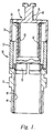
- the adjustable trimmer capacitor comprises a housing 10 in the form of a first, dielectric tubular section 12, and a second, metallic, internally screw-threaded, generally tubular electrode contact portion 14, which is an interference fit within the tubular portion 12.
- the free end of the electrode contact portion 14 is also provided with an external screw-thread 16 by means of which it may be electrically connected to other components, e.g. an electrical circuit.
- the capacitor is provided with a metallic stator electrode 18 having an inner tubular portion 20 and an outer, coaxial, tubular portion 22.
- An electrical connecting lug 24 extends from the outer surface of the circular base 26 of the stator electrode.
- the adjustable capacitor also comprises a movable, metallic "rotor" electrode having a tubular portion 30 radially outward of the inner tubular portion 20 of the stator electrode, the overlap of the tubes 20, 30 of the stator and rotor electrodes being controlled by means of a screw-threaded portion 32 of the rotor electrode assembly, which engages with the complementarily screw-threaded interior 15 of the generally tubular portion 14.
- the longitudinal axes of the electrode contact 14, the housing portion 12, the stator electrode tubes 20, 22, the rotor electrode tube 30, and the rotational axis of the screw-threaded portion 32 are all co-axial.
- the rotor electrode assembly is visible in more detail in Figs. 2 to 4.
- the assembly comprises a tubular electrode 30 having an enlarged, screw-threaded portion 32 at one end thereof.
- a slot 34 is provided, and extends for approximately half the circumference of the tubular portion 30.
- the screw-threaded portion is split by means of a further, wider, slot 36 extending parallel to the longitudinal axis of the tubular portion 30 of the electrode.
- the part-circumferential slot 34 and the longitudinal slot 36 intersect, as best seen in Figs. 2 and 3.
- the diameter of the screw-threaded portion 32 is larger than the internal diameter of the electrode contact 14. This may be because of the natural diameter of the threaded portion, or may be effected later by deformation once the slots 34, 36 are formed to increase the diameter of the threaded portion.
- the rotor electrode assembly also comprises an actuator in the form of a metal plug 38.
- the plug comprises a central cylindrical portion 40 of diameter sufficiently small to accommodate some inward deformation of the threaded portion 32 of the elctrode lying radially outwardly thereof, an enlarged head 42 having a screwdriver slot 44 disposed therein, and an enlarged base portion 46.
- the plug is inserted into the screw-threaded end of the rotor electrode, and the enlarged base 46 is an interference fit with the internal surface of the tubular portion 30 of the rotor electrode. Rotation of the plug by means of a screwdriver thereby rotates the tubular portion 30 of the rotor electrode.
- the rotor electrode assembly is inserted into the electrode contact portion 14 of the capacitor housing with the tubular portion 30 entering first.
- the screw-threaded portion 32 of the rotor electrode assembly must then be resiliently deformed to enable it to engage with the complementarily screw-threaded interior of the electrode contact portion 14 of the capacitor housing. Since the screw-threaded portion of the rotor electrode assembly is resiliently deformable, it urges itself radially outwardly into firm contact with the interior of the electrode contact portion 14 of the housing, thereby allowing rotation of the plug and the rotor electrode by means of a screwdriver, but preventing inadvertent rotation as a result of vibration, shock or other perturbations.
- a dielectric layer 48 is disposed between the stator and rotor electrodes in the embodiment illustrated, but the dielectric may be removed and may be formed by the air space between the rotor and stator electrodes.
- the spring-mounting of the rotor electrode allows the rotor to be positioned independently of the position of the rotor, thus ensuring that the capacitance of the device varies linearly with adjustment. Moreover, any small burrs produced in the formation of the longitudinal slot 36 do not bear on the thread of the electrode contact portion 14, since bending of the screw-threaded portion will tend to occur in the regions of the ends of the circumferential slot 34. Thus the edges of the slot 36 will tend to be slightly recessed from the female thread, producing a smooth torque with no generation of wear particles. Also, the effective current flow is direct to the rotor from the rotor contact 14, thus minimising contact resistance and inductance, and eliminating the need for any wear generating wiping contacts often required in conventional designs.
- the screw-threaded portion 32 may be constructed to have a natural diameter greater than the internal diameter of the contact 14, or may be outwardly deformed to increase its diameter once the slots 34, 36 have been made. In either case, the portion 32 is subject to radially inward resilient deformation when in threaded engagement with the contact 14.
Landscapes
- Engineering & Computer Science (AREA)
- Power Engineering (AREA)
- Microelectronics & Electronic Packaging (AREA)
- Fixed Capacitors And Capacitor Manufacturing Machines (AREA)
Applications Claiming Priority (2)
| Application Number | Priority Date | Filing Date | Title |
|---|---|---|---|
| GB8913362 | 1989-06-09 | ||
| GB8913362A GB2232531A (en) | 1989-06-09 | 1989-06-09 | Adjustable electrical device |
Publications (3)
| Publication Number | Publication Date |
|---|---|
| EP0401967A2 true EP0401967A2 (fr) | 1990-12-12 |
| EP0401967A3 EP0401967A3 (fr) | 1991-09-18 |
| EP0401967B1 EP0401967B1 (fr) | 1995-02-01 |
Family
ID=10658219
Family Applications (1)
| Application Number | Title | Priority Date | Filing Date |
|---|---|---|---|
| EP90304381A Expired - Lifetime EP0401967B1 (fr) | 1989-06-09 | 1990-04-24 | Dispositif électrique à régler |
Country Status (4)
| Country | Link |
|---|---|
| US (1) | US5060109A (fr) |
| EP (1) | EP0401967B1 (fr) |
| DE (1) | DE69016500D1 (fr) |
| GB (1) | GB2232531A (fr) |
Cited By (1)
| Publication number | Priority date | Publication date | Assignee | Title |
|---|---|---|---|---|
| EP0930511A3 (fr) * | 1998-01-15 | 1999-12-01 | Varian Associates, Inc. | Variable capacité externe pour sonde RMN |
Families Citing this family (3)
| Publication number | Priority date | Publication date | Assignee | Title |
|---|---|---|---|---|
| TWI394188B (zh) * | 2009-02-26 | 2013-04-21 | Asustek Comp Inc | 可拆式電容裝置 |
| US20100232083A1 (en) * | 2009-03-16 | 2010-09-16 | Mark Alan Imbimbo | Trimmer Capacitor |
| CN105843421B (zh) * | 2015-01-30 | 2018-08-21 | 禾瑞亚科技股份有限公司 | 力感应电容的组装方法 |
Family Cites Families (9)
| Publication number | Priority date | Publication date | Assignee | Title |
|---|---|---|---|---|
| US2271983A (en) * | 1937-11-30 | 1942-02-03 | Rca Corp | Capacitor |
| US3084313A (en) * | 1961-04-28 | 1963-04-02 | Erie Resistor Corp | Trimmer condenser |
| US3506894A (en) * | 1968-10-23 | 1970-04-14 | Johanson Mfg | Dual-dielectric capacitor |
| US4305113A (en) * | 1980-01-16 | 1981-12-08 | Shai Aviv B | Adjustable low loss capacitor with slotted rotor |
| US4464699A (en) * | 1982-06-22 | 1984-08-07 | Johanson Manufacturing Corporation | Shock proof adjustable low-loss capacitor |
| US4550361A (en) * | 1984-06-11 | 1985-10-29 | E. F. Johnson Company | Adjustable multiturn air dielectric capacitor |
| US4598334A (en) * | 1985-02-07 | 1986-07-01 | Tektronix, Inc. | Capacitive tuning screw |
| US4764843A (en) * | 1986-10-27 | 1988-08-16 | Voltronics Corporation | Variable electronic component |
| US4851961A (en) * | 1988-11-14 | 1989-07-25 | Funk Alexander L | Endless reactor |
-
1989
- 1989-06-09 GB GB8913362A patent/GB2232531A/en not_active Withdrawn
-
1990
- 1990-04-24 EP EP90304381A patent/EP0401967B1/fr not_active Expired - Lifetime
- 1990-04-24 DE DE69016500T patent/DE69016500D1/de not_active Expired - Lifetime
- 1990-05-09 US US07/520,723 patent/US5060109A/en not_active Expired - Fee Related
Cited By (1)
| Publication number | Priority date | Publication date | Assignee | Title |
|---|---|---|---|---|
| EP0930511A3 (fr) * | 1998-01-15 | 1999-12-01 | Varian Associates, Inc. | Variable capacité externe pour sonde RMN |
Also Published As
| Publication number | Publication date |
|---|---|
| GB2232531A (en) | 1990-12-12 |
| EP0401967B1 (fr) | 1995-02-01 |
| US5060109A (en) | 1991-10-22 |
| GB8913362D0 (en) | 1989-07-26 |
| DE69016500D1 (de) | 1995-03-16 |
| EP0401967A3 (fr) | 1991-09-18 |
Similar Documents
| Publication | Publication Date | Title |
|---|---|---|
| EP3671968B1 (fr) | Boîtier de connecteur électrique et connecteur électrique et ensemble de connecteur électrique | |
| US11381012B2 (en) | Electrical connector and electrical connector assembly | |
| US5060109A (en) | Adjustable electrical device | |
| USRE30406E (en) | Adjustable low-loss capacitor | |
| US4415949A (en) | Air trimmer capacitor | |
| CN1201426C (zh) | 滤波器 | |
| US2747147A (en) | Small capacity tubular adjustable condenser | |
| KR101381133B1 (ko) | 튜닝 요소 조립체 및 무선 주파수 구성 요소를 위한 튜닝 방법 | |
| US5659282A (en) | Cylindrical fuse holder with a socket movable axially in the holder | |
| US3329875A (en) | Variable trimmer capacitor | |
| EP1584137B1 (fr) | Systeme a vis mobile | |
| CN114243237A (zh) | 低通滤波结构及滤波器 | |
| CN120878464B (zh) | 高精度固定容值真空电容器 | |
| US3840786A (en) | Precision trimmer capacitor | |
| US3584271A (en) | Nonrotating piston trimmer capacitor | |
| CN109390139B (zh) | 点火线圈、以及将点火线圈和火花塞连接的连接构造 | |
| JPS6028121Y2 (ja) | エアトリマコンデンサ | |
| WO2006116607A2 (fr) | Condensateur a impedance non capacitive reduite | |
| US4472759A (en) | Air trimmer capacitor | |
| JPH0429555Y2 (fr) | ||
| TW382727B (en) | Deflection yoke device | |
| US3332139A (en) | Method of assembling an adjustment device for a trimmer capacitor | |
| US4584626A (en) | Electronic component having rotary mechanism | |
| JPS593562Y2 (ja) | エアトリマコンデンサ | |
| JPH0311962Y2 (fr) |
Legal Events
| Date | Code | Title | Description |
|---|---|---|---|
| PUAI | Public reference made under article 153(3) epc to a published international application that has entered the european phase |
Free format text: ORIGINAL CODE: 0009012 |
|
| AK | Designated contracting states |
Kind code of ref document: A2 Designated state(s): DE FR GB |
|
| PUAL | Search report despatched |
Free format text: ORIGINAL CODE: 0009013 |
|
| AK | Designated contracting states |
Kind code of ref document: A3 Designated state(s): DE FR GB |
|
| 17P | Request for examination filed |
Effective date: 19920310 |
|
| 17Q | First examination report despatched |
Effective date: 19930317 |
|
| GRAA | (expected) grant |
Free format text: ORIGINAL CODE: 0009210 |
|
| AK | Designated contracting states |
Kind code of ref document: B1 Designated state(s): DE FR GB |
|
| PG25 | Lapsed in a contracting state [announced via postgrant information from national office to epo] |
Ref country code: FR Effective date: 19950201 |
|
| REF | Corresponds to: |
Ref document number: 69016500 Country of ref document: DE Date of ref document: 19950316 |
|
| PG25 | Lapsed in a contracting state [announced via postgrant information from national office to epo] |
Ref country code: DE Effective date: 19950503 |
|
| EN | Fr: translation not filed | ||
| PLBE | No opposition filed within time limit |
Free format text: ORIGINAL CODE: 0009261 |
|
| STAA | Information on the status of an ep patent application or granted ep patent |
Free format text: STATUS: NO OPPOSITION FILED WITHIN TIME LIMIT |
|
| 26N | No opposition filed | ||
| PGFP | Annual fee paid to national office [announced via postgrant information from national office to epo] |
Ref country code: GB Payment date: 20010418 Year of fee payment: 12 |
|
| REG | Reference to a national code |
Ref country code: GB Ref legal event code: IF02 |
|
| PG25 | Lapsed in a contracting state [announced via postgrant information from national office to epo] |
Ref country code: GB Free format text: LAPSE BECAUSE OF NON-PAYMENT OF DUE FEES Effective date: 20020424 |
|
| GBPC | Gb: european patent ceased through non-payment of renewal fee |
Effective date: 20020424 |