EP0401984B1 - Drahtabisolierungsapparat - Google Patents
Drahtabisolierungsapparat Download PDFInfo
- Publication number
- EP0401984B1 EP0401984B1 EP90305210A EP90305210A EP0401984B1 EP 0401984 B1 EP0401984 B1 EP 0401984B1 EP 90305210 A EP90305210 A EP 90305210A EP 90305210 A EP90305210 A EP 90305210A EP 0401984 B1 EP0401984 B1 EP 0401984B1
- Authority
- EP
- European Patent Office
- Prior art keywords
- wire
- central axis
- stripping
- drive
- assemblies
- Prior art date
- Legal status (The legal status is an assumption and is not a legal conclusion. Google has not performed a legal analysis and makes no representation as to the accuracy of the status listed.)
- Expired - Lifetime
Links
- 230000000712 assembly Effects 0.000 claims abstract description 27
- 238000000429 assembly Methods 0.000 claims abstract description 27
- 230000007246 mechanism Effects 0.000 claims description 9
- 238000000576 coating method Methods 0.000 claims description 6
- 239000011248 coating agent Substances 0.000 claims description 5
- 230000002093 peripheral effect Effects 0.000 claims description 5
- 238000005096 rolling process Methods 0.000 abstract 1
- 238000009413 insulation Methods 0.000 description 14
- 238000005520 cutting process Methods 0.000 description 5
- 229920001971 elastomer Polymers 0.000 description 5
- 239000012858 resilient material Substances 0.000 description 4
- 239000000463 material Substances 0.000 description 3
- 239000002184 metal Substances 0.000 description 3
- 230000000694 effects Effects 0.000 description 2
- 239000004033 plastic Substances 0.000 description 2
- 229920003023 plastic Polymers 0.000 description 2
- 239000002966 varnish Substances 0.000 description 2
- 239000004677 Nylon Substances 0.000 description 1
- 239000004952 Polyamide Substances 0.000 description 1
- 239000004809 Teflon Substances 0.000 description 1
- 229920006362 Teflon® Polymers 0.000 description 1
- 239000000853 adhesive Substances 0.000 description 1
- 230000001070 adhesive effect Effects 0.000 description 1
- 238000013459 approach Methods 0.000 description 1
- 230000009286 beneficial effect Effects 0.000 description 1
- 238000004140 cleaning Methods 0.000 description 1
- 239000004020 conductor Substances 0.000 description 1
- 210000003298 dental enamel Anatomy 0.000 description 1
- 238000010586 diagram Methods 0.000 description 1
- 238000006073 displacement reaction Methods 0.000 description 1
- 239000000428 dust Substances 0.000 description 1
- 239000011521 glass Substances 0.000 description 1
- 239000010410 layer Substances 0.000 description 1
- 238000004519 manufacturing process Methods 0.000 description 1
- 238000000034 method Methods 0.000 description 1
- 229920001778 nylon Polymers 0.000 description 1
- 229920001084 poly(chloroprene) Polymers 0.000 description 1
- 229920002647 polyamide Polymers 0.000 description 1
- 230000008439 repair process Effects 0.000 description 1
- 239000000126 substance Substances 0.000 description 1
- 239000002344 surface layer Substances 0.000 description 1
Images

Classifications
-
- B—PERFORMING OPERATIONS; TRANSPORTING
- B24—GRINDING; POLISHING
- B24B—MACHINES, DEVICES, OR PROCESSES FOR GRINDING OR POLISHING; DRESSING OR CONDITIONING OF ABRADING SURFACES; FEEDING OF GRINDING, POLISHING, OR LAPPING AGENTS
- B24B29/00—Machines or devices for polishing surfaces on work by means of tools made of soft or flexible material with or without the application of solid or liquid polishing agents
- B24B29/005—Machines or devices for polishing surfaces on work by means of tools made of soft or flexible material with or without the application of solid or liquid polishing agents using brushes
-
- B—PERFORMING OPERATIONS; TRANSPORTING
- B24—GRINDING; POLISHING
- B24B—MACHINES, DEVICES, OR PROCESSES FOR GRINDING OR POLISHING; DRESSING OR CONDITIONING OF ABRADING SURFACES; FEEDING OF GRINDING, POLISHING, OR LAPPING AGENTS
- B24B5/00—Machines or devices designed for grinding surfaces of revolution on work, including those which also grind adjacent plane surfaces; Accessories therefor
- B24B5/36—Single-purpose machines or devices
- B24B5/38—Single-purpose machines or devices for externally grinding travelling elongated stock, e.g. wire
-
- H—ELECTRICITY
- H02—GENERATION; CONVERSION OR DISTRIBUTION OF ELECTRIC POWER
- H02G—INSTALLATION OF ELECTRIC CABLES OR LINES, OR OF COMBINED OPTICAL AND ELECTRIC CABLES OR LINES
- H02G1/00—Methods or apparatus specially adapted for installing, maintaining, repairing or dismantling electric cables or lines
- H02G1/12—Methods or apparatus specially adapted for installing, maintaining, repairing or dismantling electric cables or lines for removing insulation or armouring from cables, e.g. from the end thereof
- H02G1/1285—Methods or apparatus specially adapted for installing, maintaining, repairing or dismantling electric cables or lines for removing insulation or armouring from cables, e.g. from the end thereof by friction, e.g. abrading, grinding, brushing
Definitions
- This invention relates to wire stripping apparatus for removing insulating coating from electrical conductor wire.
- Magnet wire, transformer wire, etc. is commonly coated with a varnish insulation. Some of these wires are extremely fine, as small as about 0.0762 mm (.003 inches) in diameter. Removal of the insulation is sometimes difficult with known wire stripping apparatus. The wire may be dipped in a chemical etchant, but that is unacceptable in many instances because of the potentially corrosive residue which may remain on the wire.
- Insulating coatings other than varnish may comprise materials of enamel, plastic, nylon, woven glass, Teflon, P.V.C., neoprene, rubber, polyamide and the like.
- Stationary strippers for such insulation which have a wire guide into which the wire may be inserted for stripping contact between two oppositely rotating abrading wheels. Similar devices are used which have rotating brushes, rather than abrading wheels, to accomplish the stripping of insulation.
- GB-A-1,225,716 discloses a wire stripping apparatus including a frame member supported for rotation about a central axis, a pair of opposed assemblies mounted on the frame member for rotation therewith, each assembly including a wire stripping element mounted for rotation about an axis orthogonal to the central axis in order to strip a coating from an adjacent surface of a wire, the axis of rotation of each wire stripping element being displaced from the central axis such that the relative movement of the peripheral surface of the wire stripping element with respect to the wire is in a direction parallel to the central axis when the wire stripping element is rotated about its axis, a mechanism in each assembly for driving the wire stripping element thereof to rotate about its axis as the assembly revolves with the frame member about the central axis while stripping coating from the surface of the wire.
- the wire stripping apparatus of the present invention is characterized by a housing at least partially enclosing the frame member and having a transverse wall at one end with an opening in line with the central axis for receiving the wire, an abrading wheel acting as the wire stripping element and abrading the wire surface in a direction parallel to the central axis and away from said opening.
- Embodiments of the present invention comprise a housing having a generally flat planar end with a central bore in which a wire entry guide is mounted. This guide is removable to permit replacement with guides of different sizes to accommodate different sizes of wire.
- a rotatable shaft mounted in support bearings. The shaft supports a pair of rotatably driven roller wheel assemblies in a juxtaposition such that the stripping wheels are positioned adjacent the wire guide and on opposite sides of the central axis.
- the radial position of the stripping wheels relative to the central axis of the housing is adjustable within a predetermined range to permit use of the device with different sizes of wire and insulation.
- a drive roller is mounted in each corresponding assembly to rotate the associated stripping wheel on its axis as the assembly is rotated about the central axis.
- the drive roller and stripping wheel are mounted for rotation on shaft axes which are parallel to but displaced from each other. These shaft axes are orthogonal to the direction of the central axis.
- the two shafts carry spur gears which intermesh so that rotation of the drive roller causes the stripping wheel to rotate.
- the drive roller shafts of the two assemblies are mounted so as to be in line with each other along a diameter of the housing.
- the drive rollers are mounted near the outboard ends of the assemblies adjacent the inner surface of the cylindrical bore of the housing.
- the inner face of the end of the housing is generally flat and planar across the end of the hollow cylindrical bore and forms a cup-shaped end portion of the housing which is threadably connected to the main portion of the housing.
- the cup-shaped end portion can be readily removed to permit adjustment of the radial position of the stripping wheels, cleaning of the stripping wheels, removal of debris and dust from the wire insulation, and the like.
- a flat annular ring member is mounted to the end wall inner face. This may be fabricated of rubber or some like frictional surface material, in which case it is affixed to the end wall inner surface by a suitable adhesive.
- the drive rollers may be of metal, possibly with a machined peripheral surface adapted to develop better frictional engagement with the annular member.
- the flat annular member may be machined as a portion of the inner face of the housing end portion, in which case the drive rollers should be of rubber or a similar resilient frictional material or of metal having an outer surface layer of rubber or similar resilient material.
- the embodiment just described serves to produce rotation of the abrasive stripping wheels in opposite directions when driven by the drive rollers.
- the entire unit within the housing comprising the drive shaft, associated support frame and the two drive roller/stripping wheel assemblies, rotates with the drive shaft.
- the drive rollers are driven to rotate through the frictional engagement with the flat annular end track, thus driving the stripping wheels to rotate through the intercoupled gearing arrangements.
- the stripping wheels revolve about the axis of the housing along which the wire being stripped extends.
- the abrading or stripping action occurs about all sides of the wire so that the insulation is removed evenly throughout the complete circumference of the wire. Since the wire does not have to be rotated manually to expose the insulation on all sides to the abrading wheels, a more even, delicate stripping operation is achieved, and the wire is less likely to be damaged by the stripping device, particularly where extremely fine wires are involved.
- the drive mechanism for the stripping wheel of the respective stripping wheel assemblies comprises a directly driven gearing arrangement instead of the frictional drive rollers of the first-mentioned embodiment.
- a pin gear plate mounted within the cylindrical housing, is a pin gear plate having a central bore through which the rotatable shaft supporting the two stripping wheel assemblies extends.
- each stripping wheel is directly driven by a gear mounted on the stripping wheel shaft.
- the gearing arrangement is similar to a rack and pinion gear, except that the rack portion extends in a circle, rather than being straight, and comprises a plurality of pins having rounded ends extending from the pin gear plate in place of gear teeth.
- the "pinion” gear has a plurality of teeth especially formed to accommodate intermeshing and sliding engagement with the individual pins as the stripping wheel assemblies revolve about the central axis, the stripping wheels being driven by their respective coaxial pinion gears which are rotated by engagement with the pins of the pin gear plate.
- the action of the stripping wheels in removing insulation from wires inserted between the stripping wheels along the central bore of the apparatus is the same as that described hereinabove for the first embodiment. It has been found, however, that this arrangement operates with substantially less friction, and therefore requires less driving power, than is encountered in the first-mentioned embodiment.
- the unit is a small, hand-held device with a self-contained electric motor coupled to rotatably drive the central shaft.
- a finger switch in the housing wall permits the operator to control power to the motor, either from a self-contained power pack or from local AC mains.
- the unit is designed to be bench-mounted and its central shaft is coupled to an external pulley which may be driven by an associated electric motor.
- the central drive shaft is hollow, having a bore which extends out the rear end of the device, through the drive pulley.
- the drive roller/stripping wheel assemblies are mounted to the shaft by means of actuators which extend and retract the stripping wheels from operative positions adjacent the central axis. This enables the device to remove insulation from selected portions of the wire as it is fed through the unit. After stripping in this manner, the wire is fed to a cutting machine to be cut at the stripped portions so that individual lengths of wire having stripped ends are provided.
- the wire may be fed and stripped rapidly at selected portions in a type of step-and-repeat operation with the stripping being effected at one portion about the circumference of the wire, after which the actuators retract the stripping wheels radially outwardly, the wire is fed through the device (in through the wire guide and out through the hollow bore of the shaft at the rear end thereof) by a predetermined distance according to the desired length of the stripped wire, and the actuators extend the stripping wheels radially inward to effect the stripping at the next portion of the wire.
- FIG. 1 shows a perspective view of a first embodiment of the present invention.
- a hand-held unit 10 is shown comprising a main housing portion 12 and an end housing portion 14 threadably connected via a threaded section 16.
- the main housing portion 12 includes a generally cylindrical hand grip 18 tapering at a cone-shaped portion 20 to a distal end to which an electrical lead 22 is attached.
- a finger switch 24 is connected in the circuit to a motor within the portion 18.
- the end portion 14 comprises a hollow bore housing section 30 terminating in a flat, planar, transverse end wall 32, in the center of which is an opening 34 containing a wire guide for admitting a wire to be stripped by the unit 10.
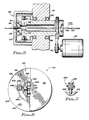
- FIGS. 2, 3 and 4 show details of the internal apparatus of the unit 10 of FIG. 1.
- a wire guide 36 is installed within the opening 34 in the end wall 32. Different wire guides 36 of different sizes may be installed to accommodate particular sizes of wire that are to be stripped.
- the cup-shaped end portion 14 is locked in place on threads 16 of the main housing 12 by means of a locknut 40.
- a motor 42 is shown within the main housing portion 12, having a shaft 44, 46 which is mounted in ball bearings 48 about the central axis 49 of the implement 10.
- Shaft 46 supports a rotatable frame 50 on which are mounted a pair of stripping assemblies 52.
- Each stripping assembly 52 includes a bracket 53 which supports a stripping wheel 54 mounted on a shaft 56 (see FIG.
- Bearing block 59 supports an additional shaft 60 on which a drive roller 62 is installed.
- the shafts 56 and 60 mount enmeshed spur gears 64, 66 in a drive arrangement which enables the rotation of the drive roller 62 to produce rotation of the associated stripping wheel 54.
- FIG. 4 is a partial sectional view taken along the line 4-4 of FIG. 3, looking in the direction of the arrows.
- the inner surface 70 of the end wall 32 is provided with an annular member 72.
- This serves as a frictional track or raceway for the drive roller 62 as the latter revolves about the central axis of the unit 10.
- the drive roller 62 is a metal wheel and the track 72 is in the form of an annular washer-like member of a resilient material such as plastic or rubber.
- the drive roller 62 may be formed of a resilient material or have a "tire" or outer layer of resilient material, in which case the annular member 72 can be dispensed with and the drive roller could merely bear against the inner surface 70 of the end wall 32.
- the operation of the device 10 can perhaps be best understood by reference to the view of FIG. 3.
- Rotation of the mounting frame 50, bearing the assemblies 52, in a counterclockwise direction as indicated by the arrows A within the end housing portion 14 produces a counterclockwise rotation of the left drive roller 62A as indicated by the arrow B, when viewed from the left-hand side of FIG. 3.
- the roller 62A moves downwardly, relative to the track 72, with rotation of the roller 62A shown in a clockwise direction (because it is viewed from the opposite end of its shaft 60).
- the lower stripping wheel 54B rotates in a clockwise direction, corresponding to the arrow C' (FIG. 3) as driven by the gear train and associated drive roller 62B, the direction of which when viewed from the right-hand side of FIG. 3 is indicated by arrow B'.
- the assemblies 52 can be adjusted in a radial direction on the rotatable frame 50 in order to accommodate different sizes of wire being stripped.
- Each of the assemblies 52 includes a bracket adjusting pin 80 and a bracket set screw 82 to control the radial position of the assembly 52.
- FIG. 5 shows a stationary frame 112 mounting a plurality of bearings 148 which rotatably support a hollow shaft 146.
- Frame 112 is adapted for mounting on a bench or the like in association with a separate drive motor 142.
- the motor 142 and shaft 146 are equipped with drive pulleys 147, 149 or equivalent sprockets so that the shaft 146 may be rotated by the motor 142 via suitable drive belts, gear belts or the like.
- Each stripping wheel 154 is coupled to, and is driven by, a suitable gear train and drive roller arrangement (not shown), the drive roller being forced to rotate in driving relationship as it moves along a raceway member 172 on the inner surface of the end wall 132.
- Each of the support assemblies 152 is mounted for radial displacement in a corresponding actuator 160 which is installed on the rotating shaft 146.
- the actuators 160 are controlled by electrical signals coupled into the rotating assembly of the device 100 by means of conventional current-conducting rings and brushes or wiper contacts, not shown.
- the apparatus of FIG. 5 is designed to be used in conjunction with a wire cutting machine (not shown) which operates in a step-and-repeat mode to draw wire 100 past a cutting knife by a predetermined length, stop the wire movement while the knife is activated to cut the wire, and then advance it again by the next length to be cut.
- a wire cutting machine not shown
- FIGS. 6 and 7 are schematic representations of a second embodiment of the drive mechanism for the wire stripping assemblies of the present invention.
- FIG. 6 schematically represents an end view of a wire stripping implement 10', having an end wall 32' in the form of a cover plate mounting a central opening 34' which contains a wire guide for admitting wire to be stripped by the unit 10'.
- the cover plate 32' is shown broken away along a vertical axis to illustrate the driving arrangement on the left half of FIG. 6.
- a transversely mounted pin plate 210 which may be in the form of a disk 212 mounted to the housing 214 by means of mounting screws 216.
- the disk 212 has a central opening 220 through which the respective stripping wheel assemblies 222 extend, mounted on suitable bearings (not shown) for rotation about the central axis of the implement 10' which is aligned with the wire guide 34'.
- Each of the wire stripping assemblies 222 comprises a mounting frame 224 having bearings (not shown) supporting a shaft 226 on which a stripping wheel 228 and a drive gear 230 are mounted so that the drive gear 230 may rotatably drive the stripping wheel 228 to develop the stripping action of a wire inserted through the wire guide 34'.
- the pin plate 210 has a plurality of pins 240 mounted in a circle thereon, preferably inserted in transverse holes drilled in the plate 210.
- One such pin 240 is shown in the schematic diagram of FIG. 7, illustrating the way in which it engages gear teeth of the drive gear 230 and causes the gear 230 to rotate on the axis of its shaft 226 as the wire stripping assembly 222 is rotatably driven to revolve about the central axis.
- the gear 230 is provided with a plurality of teeth 242, better shown in FIG. 7, which are especially curved so as to engage successive pins 240 as the gear 230 traverses the pin circle in the plate 210.
- the teeth 242 of the gear 230 must accommodate relative sliding movement of the pin 240 along the operative face of the engaged gear tooth 242, since a pin 240 enters the space between two adjacent teeth 242 near the radially inward end thereof, moves radially outward relative to the gear 230 and then moves radially inward again as it approaches the exit point.
- the gear teeth 242 are especially shaped so that the point of surface contact of the tooth is parallel to the point of surface contact of the contacting pin 240.
- This drive arrangements develops very little friction, as compared with the arrangement described in conjunction with FIGS. 2-5, and can be driven with less power.
- the effect of the wire stripping wheels 228 is the same as that described for the wire stripping wheels 54 of the other arrangement. Radial adjustment of the wire stripping assemblies is permitted in order to accommodate different sizes of wire to be stripped.
- the drive arrangement of FIGS. 6-7 can be used in place of the particular arrangement of FIGS. 2-4 in the version depicted in FIG. 5.
- Embodiments of the present invention advantageously provide for improvements in the efficiency and effectiveness of wire stripping apparatus.
- a particularly small, compact, hand-held wire stripper is provided which can be used as a portable tool for stripping wires in making circuit repairs at the site of electrical equipment, or it may be used at a work station on a production line.
- the operation of apparatus in accordance with the invention results in a complete, even removal of wire insulation all around the wire without the operator having to twist the wire as it is being stripped.
- the stripping of the insulation is accomplished by means of drawing forces only which are exerted on the wire, thus making it feasible to use the device with extremely fine, ductile wires down to as small as 0.0762 mm (.003 inches) in diameter.
- a second embodiment of the invention achieves similar beneficial results by using the equivalent wire stripping mechanism in a manner which permits drawing the wire entirely through the apparatus, thereby adapting the invention for use in conjunction with conventional step-and-repeat wire cutting machines.
Landscapes
- Engineering & Computer Science (AREA)
- Mechanical Engineering (AREA)
- Removal Of Insulation Or Armoring From Wires Or Cables (AREA)
- Coating With Molten Metal (AREA)
Claims (13)
- Drahtabisolierungsapparat (10), der ein zur Drehung um eine zentrale Achse (49) abgestütztes Rahmenbauteil (50), ein Paar von an dem Rahmenbauteil (50) zur Drehung mit diesem angebrachten gegenüberliegenden Baugruppen (52), wobei jede der Baugruppen (52) ein drahtabisolierendes Element (54) beinhaltet, das zur Drehung um eine zur zentralen Achse senkrechten Achse angebracht ist, um eine Beschichtung von einer angrenzenden Oberfläche eines Drahtes abzutragen, und die Drehachse von jedem drahtabisolierenden Element (54) bezüglich der zentralen Achse versetzt ist, so daß die Relativbewegung der Umfangsfläche des drahtabisolierenden Elementes (54) bezüglich des Drahtes in einer zur zentralen Achse parallelen Richtung stattfindet, wenn das drahtabisolierende Element um seine Achse gedreht wird, sowie einen Mechanismus (62, 64, 66) an jeder Baugruppe (52) zum Antrieb des drahtabisolierenden Elementes (54) beinhaltet, damit sich das drahtabisolierende Element (54) um seine Achse drehen kann, wenn sich die Baugruppe (52) mit dem Rahmenbauteil (50) um die zentrale Achse dreht und so lange eine Beschichtung der Oberfläche des Drahtes abgetragen wird,
dadurch gekennzeichnet, daß
ein Gehäuse (12) mindestens teilweise das Rahmenbauteil (50) enthält und eine Querwand (32) an einem Ende mit einer bezüglich der zentralen Achse fluchtenden Öffnung (34) zur Aufnahme des Drahtes besitzt, ein abschleifendes Rad (54) als das drahtabisolierende Element fungiert und die Drahtoberfläche in einer zur zentralen Achse parallelen und von der genannten Öffnung abgewandten Richtung abgeschliffen wird. - Drahtabisolierungsapparat nach Anspruch 1,
dadurch gekennzeichnet, daß
der Antriebsmechanismus eine Antriebsrolle (62) beinhaltet, die sich an der Querwand (32) abstützt und derart angekoppelt ist, daß sie das abschleifende Rad (54) drehbar antreibt. - Drahtabisolierungsapparat nach Anspruch 2,
dadurch gekennzeichnet, daß
die innere Oberfläche der Querwand (32) eine kreisförmige Laufbahn (72) besitzt, die am äußeren Umfang der Querwand (32) anliegend angeordnet ist und dazu dient, reibschlüssig an die Antriebsrollen (62) der Baugruppen (52) anzugreifen. - Drahtabisolierungsapparat nach Anspruch 1,
dadurch gekennzeichnet, daß
der Antriebsmechanismus mehrere Antriebselemente (240), die in einem Kreis angeordnet sind, der etwa senkrecht auf und konzentrisch zu der zentralen Achse orientiert ist, und ein Zahnrad (230), das an einer Welle (226) mit einem zugehörigen abschleifenden Rad (228) in einer Lage angebracht ist, in der es von den Antriebselementen gedreht wird, wenn sich die Baugruppe um die zentrale Achse dreht, beinhaltet. - Drahtabisolierungsapparat nach Anspruch 4,
dadurch gekennzeichnet, daß
die Antriebselemente (240) mehrere Antriebsstifte umfassen, die in Montagelöchern in einer quer angebrachten Stiftplatte (210) eingelassen sind. - Drahtabisolierungsapparat nach Anspruch 5,
dadurch gekennzeichnet, daß
das Zahnrad (230) mehrere Zähne (242) besitzt, die speziell geformt sind, um die relative Gleitbewegung zwischen den Zahnradzähnen (242) und den Antriebsstiften (240) anzupassen, wenn sich das Zahnrad über den Kreis aus Stiften bewegt. - Drahtabisolierungsapparat nach Anspruch 5 oder 6,
dadurch gekennzeichnet, daß
die Tangentialebene an der Kontaktoberfläche eines jeden Zahnradzahnes und die Tagentialebene an der Kontaktoberfläche eines jeden sich in Kontakt befindlichen Stiftes an jedem Berührungspunkt zwischen einem Zahn und einem Stift parallel zueinander sind. - Drahtabisolierungsapparat nach einem der Ansprüche 1 bis 7,
dadurch gekennzeichnet, daß
sich die abschleifenden Räder (54) komplett um die zentrale Achse drehen, während die Räder (54) um ihre betreffenden Achsen rotieren, um einen sich entlang der zentralen Achse erstreckenden Draht am Umfang des Drahtes komplett abzuchleifen. - Drahtabisolierungsapparat nach einem der Ansprüche 1 bis 8,
dadurch gekennzeichnet, daß
die Drehrichtung beider abschleifender Räder (54) um ihre betreffenden Achsen derart angelegt ist, daß an einen durch die Öffnung in der Querwand (32) eintretenden Draht eine Spannung angelegt wird, um den Draht in das Gehäuse (12) zu ziehen, während die äußere Oberfläche des Drahtes abgeschliffen wird. - Drahtabisolierungsapparat nach einem der Ansprüche 1 bis 9,
dadurch gekennzeichnet, daß
er eine in der Querwand (32) demontierbar angebrachte Drahtführung (36) beinhaltet und eine Führungsöffnung aufweist, die ausgewählt wurde, um mit der Größe des abzuschleifenden Drahtes zusammenzupassen. - Drahtabisolierungsapparat nach einem der Ansprüchge 1 bis 10,
dadurch gekennzeichnet, daß
er einen Motor (42) und eine zentrale Motorwelle (44) beinhaltet, die in dem genannten Gehäuse bezüglich der zentralen Achse in einer Linie ausgerichtet und angekuppelt ist, um das Rahmenbauteil (50) in Drehung um die zentrale Achse zu versetzen. - Drahtabisolierungsapparat nach einem der Ansprüche 1 bis 10, der darüber hinaus einen außerhalb des Gehäuses (12) angebrachten Motor beinhaltet, der angekuppelt ist, um das Rahmenbauteil (50) zur Drehung um die zentrale Achse anzutreiben,
dadurch gekennzeichnet, daß
das Gehäuse eine von der Querwandöffnung (34) entfernt angeordnete Ausgangs-Endöffnung aufweist, um es dem Draht zu ermöglichen, aus dem genannten Apparat (10) herausgeführt zu werden, nachdem er abgeschliffen worden ist. - Drahtabisolierungsapparat nach einem der Ansprüche 1 bis 12,
dadurch gekennzeichnet, daß
die Baugruppen (52) bezüglich des Rahmenbauteils (50) radial einstellbar sind und er außerdem einen Mechanismus (80, 82, 160) zum Einstellen der Lage der Baugruppen (52) an dem Rahmenbauteil (50) bezüglich der zentralen Achse beinhaltet.
Priority Applications (1)
| Application Number | Priority Date | Filing Date | Title |
|---|---|---|---|
| AT90305210T ATE95645T1 (de) | 1989-06-06 | 1990-05-15 | Drahtabisolierungsapparat. |
Applications Claiming Priority (2)
| Application Number | Priority Date | Filing Date | Title |
|---|---|---|---|
| US07/362,088 US5016398A (en) | 1989-06-06 | 1989-06-06 | Wire stripping apparatus |
| US362088 | 1989-06-06 |
Publications (2)
| Publication Number | Publication Date |
|---|---|
| EP0401984A1 EP0401984A1 (de) | 1990-12-12 |
| EP0401984B1 true EP0401984B1 (de) | 1993-10-06 |
Family
ID=23424658
Family Applications (1)
| Application Number | Title | Priority Date | Filing Date |
|---|---|---|---|
| EP90305210A Expired - Lifetime EP0401984B1 (de) | 1989-06-06 | 1990-05-15 | Drahtabisolierungsapparat |
Country Status (5)
| Country | Link |
|---|---|
| US (1) | US5016398A (de) |
| EP (1) | EP0401984B1 (de) |
| JP (1) | JPH0691695B2 (de) |
| AT (1) | ATE95645T1 (de) |
| DE (1) | DE69003742T2 (de) |
Cited By (1)
| Publication number | Priority date | Publication date | Assignee | Title |
|---|---|---|---|---|
| CN105680290A (zh) * | 2016-01-13 | 2016-06-15 | 西华大学 | 矩形漆包线线头柔性刷刮旋铣剥皮系统 |
Families Citing this family (31)
| Publication number | Priority date | Publication date | Assignee | Title |
|---|---|---|---|---|
| DE29716114U1 (de) * | 1997-09-08 | 1999-01-14 | MV Marketing und Vertriebs-GmbH & Co. KG Wieländer + Schill, 78054 Villingen-Schwenningen | Integrierter Doppelfalzschleifer für die handwerkgerechte Schweißvorrichtung |
| US6299518B1 (en) * | 1999-02-16 | 2001-10-09 | Thomas H. Daggett | Rotary abrasion device |
| GB2370426B (en) * | 2000-12-22 | 2003-07-09 | Antech Ltd | Cable stripping apparatus |
| WO2005056233A1 (de) * | 2003-12-12 | 2005-06-23 | Gemo G. Moritz Gmbh & Co Kg | Verfahren bzw. vorrichtung zur herstellung von verstellwellen |
| DE20319428U1 (de) * | 2003-12-12 | 2004-03-04 | Mechanik Center Erlangen Gmbh | Vorrichtung zur Herstellung von Verstellwellen |
| US8069521B2 (en) * | 2007-08-09 | 2011-12-06 | Hubbell Incorporated | Hand-held electrical conductor cleaning apparatus |
| US8272925B2 (en) * | 2009-01-07 | 2012-09-25 | Sears Brands, L.L.C. | Multi-drum sander and/or rasp |
| WO2012033746A2 (en) | 2010-09-07 | 2012-03-15 | Venmill Industries, Inc. | Illuminable wall socket plates and systems and methods thereof |
| US9917430B2 (en) | 2011-08-01 | 2018-03-13 | Snap Rays | Active cover plates |
| US11664631B2 (en) | 2011-08-01 | 2023-05-30 | Snaprays, Llc | Environment sensing active units |
| US11158982B2 (en) | 2011-08-01 | 2021-10-26 | Snaprays Llc | Active cover plates |
| US8912442B2 (en) | 2011-08-01 | 2014-12-16 | SnapPower | Active cover plate |
| US9035180B2 (en) | 2011-08-01 | 2015-05-19 | Snaprays Llc | Active cover plates |
| US9362728B2 (en) | 2011-08-01 | 2016-06-07 | SnapPower | Active cover plates |
| US10381788B2 (en) | 2011-08-01 | 2019-08-13 | Snaprays Llc | Active cover plates |
| US10381789B2 (en) | 2011-08-01 | 2019-08-13 | Snaprays Llc | Active cover plates |
| US12021335B2 (en) | 2017-02-17 | 2024-06-25 | Snaprays, Llc | Active cover plates |
| US11888301B2 (en) | 2011-08-01 | 2024-01-30 | Snaprays, Llc | Active cover plates |
| US9035181B2 (en) | 2011-08-01 | 2015-05-19 | Snaprays Llc | Modified electrical devices |
| US12142880B2 (en) | 2011-08-01 | 2024-11-12 | Snaprays, Llc | Active cover plates |
| USD882377S1 (en) | 2011-09-06 | 2020-04-28 | Snaprays Llc | Lighted wall plate |
| CN102916374B (zh) * | 2012-11-15 | 2015-04-29 | 重庆泰山电缆有限公司 | 低压电缆剥线机 |
| CN104092155B (zh) * | 2014-07-22 | 2016-08-24 | 台州美新源环保设备科技有限公司 | 一种刀辊 |
| US9966742B2 (en) | 2014-07-29 | 2018-05-08 | The Boeing Company | Apparatus for cable processing |
| US10373773B2 (en) | 2017-02-17 | 2019-08-06 | Snaprays Llc | Active cover plates |
| US10587101B2 (en) | 2017-03-29 | 2020-03-10 | The Boeing Company | Cable processing apparatus and method therefore |
| US10742005B2 (en) | 2017-04-25 | 2020-08-11 | The Boeing Company | Cable processing apparatus and method |
| CN109768506A (zh) * | 2017-11-09 | 2019-05-17 | 株式会社泉精器制作所 | 下层覆层用电线覆层剥除装置 |
| US11826868B2 (en) * | 2018-09-26 | 2023-11-28 | United States Of America As Represented By The Secretary Of The Air Force | Polishing side surfaces of fibers |
| US11381061B2 (en) | 2018-12-17 | 2022-07-05 | Ulc Technologies, Llc | System for servicing cable |
| CN113510301A (zh) * | 2021-08-20 | 2021-10-19 | 无锡旭邦精密机械有限公司 | 一种齿杆芯棒自动剥离设备 |
Family Cites Families (16)
| Publication number | Priority date | Publication date | Assignee | Title |
|---|---|---|---|---|
| US2008276A (en) * | 1934-04-17 | 1935-07-16 | Bell Telephone Labor Inc | Telephone plug cleaning machine |
| US2359568A (en) * | 1942-09-04 | 1944-10-03 | Western Electric Co | Apparatus for cleaning strands |
| US3385140A (en) * | 1967-06-15 | 1968-05-28 | Carpenter Mfg Co Inc | Flat multi-conductor stripping apparatus |
| DE1918467C3 (de) * | 1969-04-11 | 1978-10-19 | Jevgenij Nikolaevitsch Leningrad Voroncov (Sowjetunion) | Vorrichtung zum Entfernen der Abschirmung von den Enden von Leitungen oder Kabeln |
| GB1225716A (de) * | 1969-04-29 | 1971-03-24 | ||
| US3887702A (en) * | 1973-08-30 | 1975-06-03 | Mildred Baldwin | Composition and method for treating fingernails and toenails |
| US3906676A (en) * | 1974-05-31 | 1975-09-23 | Int Nickel Co | Rotary mechanical wire grinder |
| DE2540933A1 (de) * | 1975-09-13 | 1977-04-28 | Transformatoren Union Ag | Verfahren und vorrichtung zum entfernen von auf profildraehten aufgebrachten isoliermaterialien, schutzschichten und oxydationsschichten |
| US4125916A (en) * | 1977-01-17 | 1978-11-21 | Mcgraw-Edison Company | Tool for removing insulating material from electrical conductors |
| US4459881A (en) * | 1981-09-08 | 1984-07-17 | Hughes Jr Benjamin W | Cable coring and stripping tool and method |
| US4490908A (en) * | 1982-04-09 | 1985-01-01 | Associated Enterprises, Inc. | Wire stripper and method |
| US4594029A (en) * | 1982-08-17 | 1986-06-10 | Amp Incorporated | Method for trimming coaxial cable |
| US4730391A (en) * | 1985-12-23 | 1988-03-15 | Warren & Brown & Staff Pty. Ltd. | Wire stripper |
| US4729268A (en) * | 1987-02-13 | 1988-03-08 | Ben Hughes Communication Products Co. | Coaxial cable skiving tool |
| JPH062416Y2 (ja) * | 1987-05-23 | 1994-01-19 | 東神電気株式会社 | 被覆電線のセパレ−タ除去工具 |
| JPH01164209A (ja) * | 1987-12-21 | 1989-06-28 | Alps Electric Co Ltd | 電線の被覆剥離装置 |
-
1989
- 1989-06-06 US US07/362,088 patent/US5016398A/en not_active Expired - Lifetime
-
1990
- 1990-05-15 AT AT90305210T patent/ATE95645T1/de not_active IP Right Cessation
- 1990-05-15 EP EP90305210A patent/EP0401984B1/de not_active Expired - Lifetime
- 1990-05-15 DE DE90305210T patent/DE69003742T2/de not_active Expired - Fee Related
- 1990-06-05 JP JP2147186A patent/JPH0691695B2/ja not_active Expired - Fee Related
Cited By (2)
| Publication number | Priority date | Publication date | Assignee | Title |
|---|---|---|---|---|
| CN105680290A (zh) * | 2016-01-13 | 2016-06-15 | 西华大学 | 矩形漆包线线头柔性刷刮旋铣剥皮系统 |
| CN105680290B (zh) * | 2016-01-13 | 2018-08-21 | 西华大学 | 矩形漆包线线头柔性刷刮旋铣剥皮系统 |
Also Published As
| Publication number | Publication date |
|---|---|
| DE69003742D1 (de) | 1993-11-11 |
| DE69003742T2 (de) | 1994-04-28 |
| JPH0691695B2 (ja) | 1994-11-14 |
| ATE95645T1 (de) | 1993-10-15 |
| EP0401984A1 (de) | 1990-12-12 |
| US5016398A (en) | 1991-05-21 |
| JPH0322809A (ja) | 1991-01-31 |
Similar Documents
| Publication | Publication Date | Title |
|---|---|---|
| US5016398A (en) | Wire stripping apparatus | |
| US5542327A (en) | Wire stripping apparatus | |
| US6681656B2 (en) | Orbiting blade coaxial cable cutter/stripper | |
| US3976815A (en) | Method for cleaning and coating rod | |
| JPH06165336A (ja) | 高圧電線の端部外周研磨装置 | |
| US5573627A (en) | Portable taping machine | |
| KR100287812B1 (ko) | 전선껍질탈피장치 | |
| AU778357B2 (en) | Device for the manufacture of annular corrugated metal tubes | |
| KR100697219B1 (ko) | 에나멜선 탈피장치 | |
| JPS58107012A (ja) | 絶縁体剥取り装置 | |
| US3534422A (en) | Conductor stripper | |
| CN214813711U (zh) | 一种旋转除灰装置 | |
| US4261396A (en) | Machine for straightening metal wire | |
| JP2575821Y2 (ja) | ゴム、プラスチックケーブルの研磨機 | |
| CN115401575A (zh) | 一种用于电缆剥皮后铜导线旋转打磨装置 | |
| DE3124397C2 (de) | Handgerät zum staubfreien Abisolieren der Enden von Wicklungen in elektrischen Maschinen | |
| US3146526A (en) | Apparatus for preparing tubing for a sweated joint | |
| KR100736880B1 (ko) | 와이어의 버어 제거장치 | |
| CN221246156U (zh) | 一种线缆加工用表面处理装置 | |
| KR0170818B1 (ko) | 와이어 그라인딩 장치 | |
| CN222037988U (zh) | 一种金属制品表面处理设备 | |
| JP2004364439A (ja) | ケーブルの被覆削り装置 | |
| JPH03128612A (ja) | 自走式ケーブル外部導電層切削機 | |
| SU1018747A1 (ru) | Станок дл правки и очистки длинномерных цилиндрических изделий | |
| US2637864A (en) | Means for baring the ends of insulated electrical conductors |
Legal Events
| Date | Code | Title | Description |
|---|---|---|---|
| PUAI | Public reference made under article 153(3) epc to a published international application that has entered the european phase |
Free format text: ORIGINAL CODE: 0009012 |
|
| AK | Designated contracting states |
Kind code of ref document: A1 Designated state(s): AT CH DE ES FR GB IT LI SE |
|
| 17P | Request for examination filed |
Effective date: 19901213 |
|
| 17Q | First examination report despatched |
Effective date: 19920930 |
|
| GRAA | (expected) grant |
Free format text: ORIGINAL CODE: 0009210 |
|
| AK | Designated contracting states |
Kind code of ref document: B1 Designated state(s): AT CH DE ES FR GB IT LI SE |
|
| PG25 | Lapsed in a contracting state [announced via postgrant information from national office to epo] |
Ref country code: IT Free format text: LAPSE BECAUSE OF FAILURE TO SUBMIT A TRANSLATION OF THE DESCRIPTION OR TO PAY THE FEE WITHIN THE PRESCRIBED TIME-LIMIT;WARNING: LAPSES OF ITALIAN PATENTS WITH EFFECTIVE DATE BEFORE 2007 MAY HAVE OCCURRED AT ANY TIME BEFORE 2007. THE CORRECT EFFECTIVE DATE MAY BE DIFFERENT FROM THE ONE RECORDED. Effective date: 19931006 Ref country code: SE Effective date: 19931006 Ref country code: ES Free format text: THE PATENT HAS BEEN ANNULLED BY A DECISION OF A NATIONAL AUTHORITY Effective date: 19931006 |
|
| REF | Corresponds to: |
Ref document number: 95645 Country of ref document: AT Date of ref document: 19931015 Kind code of ref document: T |
|
| REF | Corresponds to: |
Ref document number: 69003742 Country of ref document: DE Date of ref document: 19931111 |
|
| ET | Fr: translation filed | ||
| PLBE | No opposition filed within time limit |
Free format text: ORIGINAL CODE: 0009261 |
|
| STAA | Information on the status of an ep patent application or granted ep patent |
Free format text: STATUS: NO OPPOSITION FILED WITHIN TIME LIMIT |
|
| 26N | No opposition filed | ||
| REG | Reference to a national code |
Ref country code: GB Ref legal event code: IF02 |
|
| PGFP | Annual fee paid to national office [announced via postgrant information from national office to epo] |
Ref country code: GB Payment date: 20060510 Year of fee payment: 17 |
|
| PGFP | Annual fee paid to national office [announced via postgrant information from national office to epo] |
Ref country code: AT Payment date: 20060511 Year of fee payment: 17 Ref country code: DE Payment date: 20060511 Year of fee payment: 17 |
|
| PGFP | Annual fee paid to national office [announced via postgrant information from national office to epo] |
Ref country code: CH Payment date: 20060515 Year of fee payment: 17 Ref country code: FR Payment date: 20060515 Year of fee payment: 17 |
|
| REG | Reference to a national code |
Ref country code: CH Ref legal event code: PL |
|
| GBPC | Gb: european patent ceased through non-payment of renewal fee |
Effective date: 20070515 |
|
| PG25 | Lapsed in a contracting state [announced via postgrant information from national office to epo] |
Ref country code: LI Free format text: LAPSE BECAUSE OF NON-PAYMENT OF DUE FEES Effective date: 20070531 Ref country code: AT Free format text: LAPSE BECAUSE OF NON-PAYMENT OF DUE FEES Effective date: 20070515 Ref country code: CH Free format text: LAPSE BECAUSE OF NON-PAYMENT OF DUE FEES Effective date: 20070531 |
|
| REG | Reference to a national code |
Ref country code: FR Ref legal event code: ST Effective date: 20080131 |
|
| PG25 | Lapsed in a contracting state [announced via postgrant information from national office to epo] |
Ref country code: DE Free format text: LAPSE BECAUSE OF NON-PAYMENT OF DUE FEES Effective date: 20071201 |
|
| PG25 | Lapsed in a contracting state [announced via postgrant information from national office to epo] |
Ref country code: GB Free format text: LAPSE BECAUSE OF NON-PAYMENT OF DUE FEES Effective date: 20070515 |
|
| PG25 | Lapsed in a contracting state [announced via postgrant information from national office to epo] |
Ref country code: FR Free format text: LAPSE BECAUSE OF NON-PAYMENT OF DUE FEES Effective date: 20070531 |