EP0401986A2 - Fabrication d'un hologramme - Google Patents
Fabrication d'un hologramme Download PDFInfo
- Publication number
- EP0401986A2 EP0401986A2 EP90305281A EP90305281A EP0401986A2 EP 0401986 A2 EP0401986 A2 EP 0401986A2 EP 90305281 A EP90305281 A EP 90305281A EP 90305281 A EP90305281 A EP 90305281A EP 0401986 A2 EP0401986 A2 EP 0401986A2
- Authority
- EP
- European Patent Office
- Prior art keywords
- illuminating beam
- illuminating
- movement
- photosensitive film
- beams
- Prior art date
- Legal status (The legal status is an assumption and is not a legal conclusion. Google has not performed a legal analysis and makes no representation as to the accuracy of the status listed.)
- Withdrawn
Links
Images
Classifications
-
- G—PHYSICS
- G03—PHOTOGRAPHY; CINEMATOGRAPHY; ANALOGOUS TECHNIQUES USING WAVES OTHER THAN OPTICAL WAVES; ELECTROGRAPHY; HOLOGRAPHY
- G03H—HOLOGRAPHIC PROCESSES OR APPARATUS
- G03H1/00—Holographic processes or apparatus using light, infrared or ultraviolet waves for obtaining holograms or for obtaining an image from them; Details peculiar thereto
- G03H1/04—Processes or apparatus for producing holograms
Definitions
- the present invention relates to hologram construction and more particularly to a method and apparatus for constructing holograms and holograms made by use of such method and apparatus.
- a single beam of radiation emanating from a single beam source (usually a laser) is split into two separate expanded beams (object and reference beams) of radiation.
- the two separate beams which are conveniently of roughly equal intensity, are combined at the hologram plate which causes high contrast interference fringes to be generated in the region of overlap of the beams at the hologram plate.
- These fringes may be recorded on a suitable photosensitive material or film (e.g. dichromated gelatin photoresist, silver halide), overlaying the plate, by development and processing of the film. This constitutes the hologram.
- interference fringe shifts may be caused by vibration within the optical system, the effects of movement of the air in the system, the effects of heating of the system and so on.
- the effect on the recorded fringe pattern in these circumstances is generally proportional to the duration of exposure of the hologram.
- the laser beam intensity profile may take a number of different forms, the precise form depending on the operating mode of the laser and it is known that it is not easy to achieve a uniform exposure of the hologram over the hologram aperture with any of these modes.
- a solution which is normally adopted, however, is to use the central portion of the Gaussian beam intensity profile of a TEMoo mode of the laser.
- An aim of this invention is to provide a method and apparatus for constructing holograms which substantially reduce the effects of the aforementioned problems.
- a method of constructing a hologram including the steps of directing at least first and second separate illuminating beams towards a photosensitive film from separate independent substantially fixed apparent beam source positions respectively, overlapping the first and second illuminating beams where they are incident at the photosensitive film, generating stationary interference fringes in the region of the overlapping beams and moving the first and second illuminating beams relative to the photosensitive film in a manner which maintains said overlapping throughout exposure of the photosensitive film to record the stationary interference fringes.
- the first and second illuminating beam movement relative to the photosensitive film is desirably a pattern of movement such as a scanning movement which is preferably a raster scanning movement.
- Scanning movement of the first and second illuminating beams may be effected by separate single point scanning devices positioned at said substantially fixed apparent beam source positions respectively, the separate scanning devices being controlled by scanning information from respective independent control means.
- the method further comprises superimposing a third illuminating beam upon the first illuminating beam at a point in the first illuminating beam whereby the third illuminating beam path is coincident with the first illuminating beam path and the third illuminating beam follows the pattern of movement of the first illuminating beam exactly.
- the method further comprises scattering light from the third illuminating beam where it is incident at the photosensitive film and imaging a proportion of the scattered light by way of the single point scanning device related to the second illuminating beam towards a detection means which is adapted to provide scanning information concerning the pattern of movement of the proportion of scattered light from the third illuminating beam.
- the method further comprises controlling the independent control means associated with the second illuminating beam with said scanning information from the detection means to move the single point scanning device related to the second illuminating beam in a pattern of movement which tracks the proportion of scattered light from the third illuminating beam and thereby maintain the overlap of the second and first illuminating beams.
- the wavelength of the third illuminating beam is preferably 633 nm and is non-actinic in order not to expose the photosensitive film.
- the method comprises preventing the second illuminating beam imaging through the related single point scanning device, replacing the photosensitive film with a light scattering means, scattering light from the first illuminating beam where it is incident at the light scattering means and imaging a portion of the scattered light by way of the single point scanning device related to the second illuminating beam on to a detector means which is adapted to provide information concerning the pattern of movement of the proportion of scattered light from the first illuminating beam, controlling the independent control means associated with the second illuminating beam with scanning information from the detector means to move the single point scanning device related to the second illuminating beam to track the pattern of movement of the proportion of the scattered light from the first illuminating beam and memorising this scanning information together with scanning information from the independent control means associated with the single point scanning device related to the first illuminating beam.
- the method further comprises imaging the second illuminating beam through the related scanning device, replacing the light scattering means with the photosensitive film and using the respective memorised scanning information concurrently to control the pattern of movement of the respective single point scanning devices to thereby maintain the overlap of the second and first illuminating beams.
- the illuminating beams are preferably laser beams.
- the present invention further provides apparatus for constructing a hologram, the apparatus comprising at least one light emitter, beam splitting means for directing light emanating from said at least one light emitter into first and second separate illuminating beams, two separate moveable optical, preferably reflection, means which are arranged for directing the first and second illuminating beams from apparent beam source positions respectively towards a photosensitive film, and independent control means for controlling movement of the moveable optical means respectively, whereby the first and second separate illuminating beams are directed towards the two separate moveable optical means respectively and therefrom towards the photosensitive film where it is arranged that the beams overlap at the point where they are incident at the photosensitive film to thereby generate stationary interference fringes and the independent control means are adapted to move the first and second illuminating beams respectively relative to the photosensitive film in a manner which maintains said overlap throughout exposure of the photosensitive film to record the stationary interference fringes.
- the moveable optical, preferably reflection, means are preferably constituted by single point scanning devices which are arranged to move the first and second illuminating beams respectively relative to the photosensitive film in a scanning movement which is preferably of the raster type.
- Preferably scanning information for controlling movement of the single point scanning devices is provided by the independent control means respectively.
- Apparatus preferably comprises a further light emitter and a first wavelength filter means positioned in the path of the first illuminating beam between the beamsplitting means and the single point scanning means related to the first illuminating beam, whereby the further light emitter produces a third illuminating beam at a wavelength of preferably 633 nm which is non-actinic, whereby the third illuminating beam is superimposed upon the first illuminating beam by way of the first wavelength filter means such that the third illuminating beam follows the pattern of movement of the first illuminating beam exactly.
- Apparatus further preferably comprises a second wavelength filter means positioned in the path of the second illuminating beam between the beam splitting means and the single point scanning device related to the second illuminating beam and a detector means which provides scanning information, whereby a proportion of the scattered light from the third illuminating beam which is scattered where it is incident at the photosensitive film, is imaged by way of the single point scanning device related to the second illuminating beam on to the detector means by way of the second wavelength filter means and the scanning information, provided by the detector means, is concerned with the pattern of movement of the proportion of scattered light from the third illuminating beam.
- the independent control means associated with the second illuminating beam is controlled by the scanning information from the detection means to move the single point scanning device related to the second illuminating beam in a pattern of movement which tracks the portion of the scattered light from the third illuminating beam to maintain the overlap of the second and first illuminating beams.
- the apparatus comprises in the first stage operating means, which may be mechanical or electromechanical, for
- the said operating means a) effects replacement of the light scattering means with the photosensitive film, b) removes the beam stop from the second illuminating beam and c) removes the fixed reflection means from the second illuminating beam effectively switching the detector means out of use, whereby data signals representing the respective memorised scanning information are directed concurrently to the respective independent control means respectively to control the pattern of movement of the respective single point scanning devices to maintain the overlap of the second and first illuminating beams.
- the light emitters are preferably lasers.
- the invention provides either a reflection hologram or a transmission hologram made by a method and/or by use of apparatus as set forth above.
- a method for the construction of reflection holograms using a 'fixed source' scanning arrangement is disclosed in GB patent No. 2159979 where a single front surface scanning mirror is angularly moveable about two orthogonal axes of rotation which lie in the plane of the mirror and intersect at a point where light providing the illuminating beam is reflected from the mirror.
- the incident light is focussed onto the mirror at this point so that the illuminating beam for the hologram construction always appears to diverge from it. That point therefore constitutes a substantially fixed apparent beam source position which remains stationary relative to the film over which the beam is scanned.
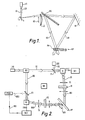
- a diffraction limited laser beam LB emanating from a laser LS is focussed by means of a lens L1 on to a single point scanning device S including a reflection means in the form of a scanning mirror (see patent GB 2159979 for type of scanner which is suitable) which provides for a raster type scanning RS movement of the beam across a lens L2 and beamsplitter BS.
- the scanning beam is split into two separate beams B1, the object beam, and B2, the reference beam and both beams are directed (beam B1 being reflected by plane mirror M) towards a hologram plate HP which carries a photosensitive film PM, where they are combined, i.e. overlap. Interference fringes are formed at the region of overlap and these are recorded by the film.
- each point on the hologram Due to the single point nature of the scanning technique, relatively no shift in interference fringes occurs during the scan as each point on the hologram receives radiation from the same two directions and with the same phase difference.
- each point on the hologram is exposed with a powerful laser beam for only a short period of time, as a consequence of which the system is far less susceptible to instability problems, especially those which would be due to longer term drifts e.g. movement of air and thermal effects.
- each point on the hologram should receive the same amount of exposure thereby improving uniformity of exposure.
- the main restriction on the use of a two-beam scanning arrangement as outlined above, is the requirement for there to be significant overlap of the two beams at the hologram plate at all points over the hologram aperture. For the system shown in Fig. 1, this may be satisfied providing the object beam B1 and the reference beam B2 are maintained incident at equal angles to the hologram plate.
- the techniques proposed by the present invention provide a solution to the problem of beam overlap enabling the application of a two-beam scanning technique to a generalised two-beam hologram configuration.
- each beam originates from a substantially fixed apparent beam source in the form of an independent single point scanning device (S1 and S2) of the type disclosed in patent GB 2159979 which incorporates a moveable reflection means in the form of a mirror in the manner previously explained.
- One of the scanning devices S1 is arranged to perform a conventional raster scanning movement RS of one of the beams through construction optics O1 on to the hologram plate HP while the other scanning device S2 is arranged to be synchronised with the scanning pattern generated at the hologram plate by the object beam B1.
- the scanning pattern may have become distorted by the construction optics O1
- the reference beam B2 will follow the distorted pattern exactly, e.g. it will automatically track the pattern by way of optics O2, regardless of however complex it is, so that an overlap of the beams is maintained at all points over the hologram aperture.
- this arrangement may be termed a "real time tracking" system as it is arranged for one of the scanning devices to automatically "lock-on" to the scanning pattern of the other.
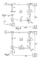
- the input beam from a light emitter in the form of a laser LS1 is split into two separate beams B1 and B2 by a beam splitter BS and each beam is directed to an accurately aligned and focussed single point scanning device S1 and S2 respectively.
- each scanner moves its respective beam in a raster type scanning pattern RS on to the hologram recording plate HP through respective optics O1 and O2 whereby the beams overlap at the hologram plate HP where stationary interference fringes are generated and recorded by a photosensitive film of the plate.
- the optics O1 and O2 are appropriate to the holographic optical element to be recorded and generally may be of a complicated arbitrary nature causing distortion of the raster scanning patterns.
- a third beam B3 emanating from a light emitter in the form of a laser LS2 is superimposed on to beam B1 by way of a wavelength filter F1 so that both beam paths are coincident.
- the third beam B3 is subjected to a raster scanning movement by scanning device S1 which is controlled by a raster scanning signal RSG emanating from an independent control means hereafter referred to as scanning control means SC1.
- Beam 83 is at a different wavelength ⁇ b to that of the exposure wavelength ⁇ a of beams B1 and B2, and is non-actinic (i.e. it will not expose the hologram).
- the wavelength ⁇ b is typically 633 nm when using dichromated gelatin as the photosensitive film.
- a proportion of beam B3 is scattered as indicated by the designation SB3 and a small proportion of this scattered light SB3 is directed by way of optics O2 and imaged through the scanning device S2 on to a wavelength filter F2 where the beam B3 is picked-off and directed to a position sensitive detector PSD for detection.
- the output of the position sensitive detector PSD is directed to a further independent control means hereafter referred to as scanning control means SC2 as a feed-back signal FBS which thereby controls through a tracking signal TSG the movement of the scanning device S2, ensuring that it follows or tracks the scattered light SB3 from the hologram. Since scanning device S2 is simultaneously directing beam B2 on to the hologram as a tracking scan TS, beam B2 will always overlap beams B1 and B3 throughout the exposure process.
- this arrangement may be termed a "memorised scan” system.
- This system is arranged to operate in two sequential stages, stage 1 where the scanning patterns are memorised and stage 2 where the memorised scanning patterns are "played-back" to control both the scanning devices to record the hologram.
- CM data storage or memory means
- processing control apparatus PC which enables the storage and manipulation of the data signals representing the scanning patterns from both scanning control means SC1 and SC2.
- beam B2 is suitably obstructed by means of an appropriately positioned beam stop BSP to prevent the illumination beam B2 being imaged through the related scanning device S2, and a plane mirror PM is substituted in the position occupied in the Figure 2 embodiment by the wavelength filter F2.
- the position normally occupied by the hologram plate is occupied by a diffuse scattering plate SP.
- the positioning of the beam stop BSP, the plane mirror PM and the diffuse scattering plate SP may be effected by operating means OM located at the appropriate parts of the apparatus.
- the operating means OM may for example be mechanically or electromechanically activated.
- the scanning signals which are controlling both scanning devices S1 and S2 are directed as signals MPSG1 and MPSG2 respectively to be memorised in the storage means CM.
- the scanning speed may be reduced to a rate sufficient to eliminate any tracking errors or other practical limitations of the tracking system during this stage of the sequence.
- the scattering plate SP is replaced by a hologram plate HP in which a hologram is to be recorded.
- the beam stop BSP and the plane mirror PM are removed and the beam B2 directed on to the scanning device S2.
- the position signal detector PSG is effectively switched-out of use.
- the storage means CM is arranged to send position data signals PSG1 and PSG2 representing the stored scanning patterns to the scanning control means SC1 and SC2 respectively.
- the raster scanning signal RSG and the tracking signal TSG now control the movement of the scanning devices S1 and S2 respectively ensuring that beams B1 and B2 will always overlap throughout the exposure process.
- Stage 1 of the sequence need only be performed once for any given optical arrangement in order to perform and track the scanning patterns.
- Stage 2 is then performed for each and every other hologram recording with this given optical arrangement.
- transmission type holograms may be readily constructed using the principles of this invention by rearranging the illuminating beam geometrics so that the illuminating beams are directed towards the hologram plate from one side only.
Landscapes
- Physics & Mathematics (AREA)
- General Physics & Mathematics (AREA)
- Holo Graphy (AREA)
- Mechanical Optical Scanning Systems (AREA)
Applications Claiming Priority (2)
| Application Number | Priority Date | Filing Date | Title |
|---|---|---|---|
| GB8911454 | 1989-05-18 | ||
| GB898911454A GB8911454D0 (en) | 1989-05-18 | 1989-05-18 | Hologram construction |
Publications (2)
| Publication Number | Publication Date |
|---|---|
| EP0401986A2 true EP0401986A2 (fr) | 1990-12-12 |
| EP0401986A3 EP0401986A3 (fr) | 1992-01-02 |
Family
ID=10656973
Family Applications (1)
| Application Number | Title | Priority Date | Filing Date |
|---|---|---|---|
| EP19900305281 Withdrawn EP0401986A3 (fr) | 1989-05-18 | 1990-05-16 | Fabrication d'un hologramme |
Country Status (4)
| Country | Link |
|---|---|
| US (2) | US5208123A (fr) |
| EP (1) | EP0401986A3 (fr) |
| JP (1) | JPH036585A (fr) |
| GB (2) | GB8911454D0 (fr) |
Cited By (2)
| Publication number | Priority date | Publication date | Assignee | Title |
|---|---|---|---|---|
| EP0499372A3 (en) * | 1991-02-11 | 1993-10-06 | Hughes Aircraft Company | System and technique for making holographic projection screens |
| CN100523916C (zh) * | 2006-10-20 | 2009-08-05 | 中山大学 | 一种全息印刷技术中光场的控制方法及其系统 |
Families Citing this family (18)
| Publication number | Priority date | Publication date | Assignee | Title |
|---|---|---|---|---|
| US5415835A (en) * | 1992-09-16 | 1995-05-16 | University Of New Mexico | Method for fine-line interferometric lithography |
| WO1998021629A2 (fr) * | 1996-11-15 | 1998-05-22 | Diffraction, Ltd. | Masque holographique en ligne destine au micro-usinage |
| US6360134B1 (en) | 1998-07-20 | 2002-03-19 | Photronics, Inc. | Method for creating and improved image on a photomask by negatively and positively overscanning the boundaries of an image pattern at inside corner locations |
| US6882477B1 (en) | 1999-11-10 | 2005-04-19 | Massachusetts Institute Of Technology | Method and system for interference lithography utilizing phase-locked scanning beams |
| JP4965052B2 (ja) * | 2000-06-15 | 2012-07-04 | スリーエム イノベイティブ プロパティズ カンパニー | 3次元光学素子の加工方法 |
| ATE440305T1 (de) * | 2000-06-15 | 2009-09-15 | 3M Innovative Properties Co | Erzeugung eines mehrfarbenbildes mittels eines multiphoton photochemischen verfahren |
| WO2001096959A2 (fr) * | 2000-06-15 | 2001-12-20 | 3M Innovative Properties Company | Procede d'absorption photoreactive multidirectionnelle |
| KR100795759B1 (ko) * | 2000-06-15 | 2008-01-21 | 쓰리엠 이노베이티브 프로퍼티즈 캄파니 | 미세유체 물품의 제조 방법 |
| JP2004503831A (ja) | 2000-06-15 | 2004-02-05 | スリーエム イノベイティブ プロパティズ カンパニー | マルチパス多光子吸収方法および装置 |
| WO2001096917A2 (fr) | 2000-06-15 | 2001-12-20 | 3M Innovative Properties Company | Polymerisation multiphotonique permettant d'obtenir des elements optiques encapsules |
| US6852766B1 (en) * | 2000-06-15 | 2005-02-08 | 3M Innovative Properties Company | Multiphoton photosensitization system |
| US6476944B1 (en) * | 2000-10-18 | 2002-11-05 | Joseph A. La Russa | Image-forming apparatus |
| US20040012872A1 (en) * | 2001-06-14 | 2004-01-22 | Fleming Patrick R | Multiphoton absorption method using patterned light |
| US6633385B2 (en) * | 2001-10-11 | 2003-10-14 | Teraxion Inc. | System and method for recording interference fringes in a photosensitive medium |
| GB2429865B (en) * | 2005-09-06 | 2011-02-23 | Cintel Internat Ltd | Optical scatter correction for film scanners |
| US7864388B2 (en) * | 2005-11-17 | 2011-01-04 | Raytheon Company | Method and apparatus for recoding holographic diffraction gratings |
| US8257885B1 (en) * | 2006-12-07 | 2012-09-04 | Hrl Laboratories, Llc | Recording reflection Bragg Gratings and apodizing reflection Bragg Gratings |
| CN102636004B (zh) * | 2012-03-26 | 2014-08-27 | 曲靖博浩生物科技股份有限公司 | 双悬浮间歇轮换排料的气流悬浮烘干装置 |
Family Cites Families (15)
| Publication number | Priority date | Publication date | Assignee | Title |
|---|---|---|---|---|
| US3572878A (en) * | 1967-09-11 | 1971-03-30 | Texas Instruments Inc | Complex spatial filter synthesis |
| US3650605A (en) * | 1970-10-15 | 1972-03-21 | Xerox Corp | Interferometric apparatus with controlled scanning means |
| US3829838A (en) * | 1970-11-05 | 1974-08-13 | Battelle Development Corp | Computer-controlled three-dimensional pattern generator |
| US3706080A (en) * | 1971-06-01 | 1972-12-12 | Honeywell Inc | Holographic optical memory having pivot lens apparatus |
| US3698789A (en) * | 1971-10-20 | 1972-10-17 | Bendix Corp | Apparatus employing a grating to provide and move the source of a wave energy distribution |
| US4093338A (en) * | 1976-01-12 | 1978-06-06 | Bell Telephone Laboratories, Incorporated | Apparatus for piecewise generation of grating-like patterns |
| DE2963917D1 (en) * | 1978-02-28 | 1982-12-02 | Shimano Industrial Co | A wheel hub for a spoked wheel and use thereof |
| CA1090630A (fr) * | 1978-11-27 | 1980-12-02 | Maurice Cormier | Corps plastique d'enregistrement en holographie |
| GB2071866B (en) * | 1980-03-13 | 1983-11-16 | Marconi Co Ltd | Colour selective holographic reflector |
| DE3142152C2 (de) * | 1981-10-23 | 1984-05-24 | Siemens AG, 1000 Berlin und 8000 München | Vorrichtung zum automatischen Abgleich der Kennlinie einer Ablenkeinheit |
| US4714309A (en) * | 1984-06-09 | 1987-12-22 | Pilkington P.E. Limited | Reflection holograms |
| JPS62501380A (ja) * | 1984-12-28 | 1987-06-04 | エヌ・シ−・ア−ル・コ−ポレ−シヨン | ガウス・レ−ザ・ビ−ム・フイルタの作成方法 |
| EP0218555A3 (fr) * | 1985-10-11 | 1989-05-17 | Gesellschaft zur Förderung der industrieorientierten Forschung an den Schweizerischen Hochschulen und weiteren Institutionen | Procédé et dispositif pour la déflexion variable de la lumière et/ou pour la modulation spatiale de la lumière par diffraction |
| US4863225A (en) * | 1986-03-26 | 1989-09-05 | Gec Avionics Limited | Reflection holograms formed by scanning |
| GB8803283D0 (en) * | 1988-02-12 | 1988-03-09 | Ciba Geigy Ag | Copying holograms |
-
1989
- 1989-05-18 GB GB898911454A patent/GB8911454D0/en active Pending
-
1990
- 1990-05-16 EP EP19900305281 patent/EP0401986A3/fr not_active Withdrawn
- 1990-05-16 GB GB9011018A patent/GB2231973B/en not_active Expired - Fee Related
- 1990-05-17 JP JP2128079A patent/JPH036585A/ja active Pending
- 1990-05-17 US US07/524,656 patent/US5208123A/en not_active Expired - Fee Related
-
1993
- 1993-04-30 US US08/055,961 patent/US5479273A/en not_active Expired - Fee Related
Cited By (2)
| Publication number | Priority date | Publication date | Assignee | Title |
|---|---|---|---|---|
| EP0499372A3 (en) * | 1991-02-11 | 1993-10-06 | Hughes Aircraft Company | System and technique for making holographic projection screens |
| CN100523916C (zh) * | 2006-10-20 | 2009-08-05 | 中山大学 | 一种全息印刷技术中光场的控制方法及其系统 |
Also Published As
| Publication number | Publication date |
|---|---|
| GB8911454D0 (en) | 1989-07-05 |
| GB2231973A (en) | 1990-11-28 |
| GB9011018D0 (en) | 1990-07-04 |
| EP0401986A3 (fr) | 1992-01-02 |
| US5208123A (en) | 1993-05-04 |
| JPH036585A (ja) | 1991-01-14 |
| GB2231973B (en) | 1993-11-17 |
| US5479273A (en) | 1995-12-26 |
Similar Documents
| Publication | Publication Date | Title |
|---|---|---|
| US5208123A (en) | Hologram construction | |
| US7372602B2 (en) | Method for recording and reproducing holographic data and an apparatus therefor | |
| US4998787A (en) | Method of fabricating a multiple holographic lens | |
| JP2001056944A (ja) | 光ディスク装置及び光ディスク装置のフォーカス制御方法 | |
| JP2774398B2 (ja) | ホログラム作成装置 | |
| JP2932262B2 (ja) | ホログラムメモリ装置 | |
| GB2043294A (en) | Optical device for holographic printing planar objects | |
| JP4205996B2 (ja) | ホログラフィック記録システム及び光学チョッパー | |
| US7333251B2 (en) | Holographic data recording apparatus and method | |
| JPS62232611A (ja) | 画像走査記録装置のレ−ザ露光装置 | |
| JP2803434B2 (ja) | 回折格子プロッター | |
| KR100378628B1 (ko) | 기록트랙을가지는기록매체에대한기록및/또는재생동안정보를비접촉광학주사하기위한장치 | |
| JP2006154603A (ja) | ホログラム記録装置 | |
| WO2006003457A1 (fr) | Dispositif optique, systeme optique et procede de fabrication d'un element optique holographique | |
| EP0292209A1 (fr) | Méthode pour réduire la granulation dans une reconstruction d'une image holographique par laser | |
| US3782825A (en) | Method and apparatus for checking the stability of a setup for making reflection type holograms | |
| JP2830530B2 (ja) | 回折格子プロッター | |
| JP2005309007A (ja) | ホログラフィック記録方法及びホログラフィック記録装置 | |
| JPS61294480A (ja) | ホログラム格子記録方法 | |
| KR20100104802A (ko) | 각도 다중화를 이용한 홀로그램 기록 장치 | |
| JPH06103615A (ja) | 光ディスク原盤露光装置 | |
| JPH0312914A (ja) | パターン露光方法 | |
| JPH0244429B2 (fr) | ||
| JPH02206041A (ja) | 露光装置 | |
| JPH1039125A (ja) | 回折格子の作製方法および二光束干渉露光装置 |
Legal Events
| Date | Code | Title | Description |
|---|---|---|---|
| PUAI | Public reference made under article 153(3) epc to a published international application that has entered the european phase |
Free format text: ORIGINAL CODE: 0009012 |
|
| AK | Designated contracting states |
Kind code of ref document: A2 Designated state(s): BE DE FR GB IT NL |
|
| PUAL | Search report despatched |
Free format text: ORIGINAL CODE: 0009013 |
|
| AK | Designated contracting states |
Kind code of ref document: A3 Designated state(s): BE DE FR GB IT NL |
|
| 17P | Request for examination filed |
Effective date: 19920629 |
|
| 17Q | First examination report despatched |
Effective date: 19940310 |
|
| RBV | Designated contracting states (corrected) |
Designated state(s): BE DE FR IT NL |
|
| STAA | Information on the status of an ep patent application or granted ep patent |
Free format text: STATUS: THE APPLICATION IS DEEMED TO BE WITHDRAWN |
|
| 18D | Application deemed to be withdrawn |
Effective date: 19951208 |