EP0402115B1 - Einrichtung und Verfahren zur Fehlererkennung und Fehlerkorrektur - Google Patents
Einrichtung und Verfahren zur Fehlererkennung und Fehlerkorrektur Download PDFInfo
- Publication number
- EP0402115B1 EP0402115B1 EP90306151A EP90306151A EP0402115B1 EP 0402115 B1 EP0402115 B1 EP 0402115B1 EP 90306151 A EP90306151 A EP 90306151A EP 90306151 A EP90306151 A EP 90306151A EP 0402115 B1 EP0402115 B1 EP 0402115B1
- Authority
- EP
- European Patent Office
- Prior art keywords
- error
- code
- error correction
- mode
- codes
- Prior art date
- Legal status (The legal status is an assumption and is not a legal conclusion. Google has not performed a legal analysis and makes no representation as to the accuracy of the status listed.)
- Expired - Lifetime
Links
- 238000012937 correction Methods 0.000 title claims description 119
- 238000000034 method Methods 0.000 title claims description 38
- 238000001514 detection method Methods 0.000 title claims description 23
- 208000011580 syndromic disease Diseases 0.000 claims description 30
- 230000005540 biological transmission Effects 0.000 claims description 23
- 238000004364 calculation method Methods 0.000 description 18
- 238000010586 diagram Methods 0.000 description 9
- 230000006866 deterioration Effects 0.000 description 5
- 230000000694 effects Effects 0.000 description 3
- 238000000926 separation method Methods 0.000 description 2
- 230000001360 synchronised effect Effects 0.000 description 2
Images


Classifications
-
- H—ELECTRICITY
- H03—ELECTRONIC CIRCUITRY
- H03M—CODING; DECODING; CODE CONVERSION IN GENERAL
- H03M13/00—Coding, decoding or code conversion, for error detection or error correction; Coding theory basic assumptions; Coding bounds; Error probability evaluation methods; Channel models; Simulation or testing of codes
- H03M13/29—Coding, decoding or code conversion, for error detection or error correction; Coding theory basic assumptions; Coding bounds; Error probability evaluation methods; Channel models; Simulation or testing of codes combining two or more codes or code structures, e.g. product codes, generalised product codes, concatenated codes, inner and outer codes
- H03M13/2906—Coding, decoding or code conversion, for error detection or error correction; Coding theory basic assumptions; Coding bounds; Error probability evaluation methods; Channel models; Simulation or testing of codes combining two or more codes or code structures, e.g. product codes, generalised product codes, concatenated codes, inner and outer codes using block codes
-
- G—PHYSICS
- G11—INFORMATION STORAGE
- G11B—INFORMATION STORAGE BASED ON RELATIVE MOVEMENT BETWEEN RECORD CARRIER AND TRANSDUCER
- G11B20/00—Signal processing not specific to the method of recording or reproducing; Circuits therefor
- G11B20/10—Digital recording or reproducing
- G11B20/18—Error detection or correction; Testing, e.g. of drop-outs
- G11B20/1833—Error detection or correction; Testing, e.g. of drop-outs by adding special lists or symbols to the coded information
-
- H—ELECTRICITY
- H03—ELECTRONIC CIRCUITRY
- H03M—CODING; DECODING; CODE CONVERSION IN GENERAL
- H03M13/00—Coding, decoding or code conversion, for error detection or error correction; Coding theory basic assumptions; Coding bounds; Error probability evaluation methods; Channel models; Simulation or testing of codes
- H03M13/03—Error detection or forward error correction by redundancy in data representation, i.e. code words containing more digits than the source words
- H03M13/05—Error detection or forward error correction by redundancy in data representation, i.e. code words containing more digits than the source words using block codes, i.e. a predetermined number of check bits joined to a predetermined number of information bits
-
- H—ELECTRICITY
- H03—ELECTRONIC CIRCUITRY
- H03M—CODING; DECODING; CODE CONVERSION IN GENERAL
- H03M13/00—Coding, decoding or code conversion, for error detection or error correction; Coding theory basic assumptions; Coding bounds; Error probability evaluation methods; Channel models; Simulation or testing of codes
- H03M13/29—Coding, decoding or code conversion, for error detection or error correction; Coding theory basic assumptions; Coding bounds; Error probability evaluation methods; Channel models; Simulation or testing of codes combining two or more codes or code structures, e.g. product codes, generalised product codes, concatenated codes, inner and outer codes
Definitions
- the present invention relates to an error detection and correction circuit, and more particularly to a circuit for detecting and correcting an error of a code train transmitted via a transmission path such as a magnetic recording/reproducing system. It also relates to the corresponding method.
- a recording/reproducing system for digital data i.e., in a data transmission system
- error detection and correction codes are generally used for correcting an error code generated during the data transmission.
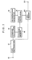
- Fig.1 is a block diagram showing an example of the circuit arrangement of a conventional error detection and correction circuit.
- Digital data (code train) is inputted to an input terminal 10, the digital data having been error-correction coded at the recording (or transmitting) side and passed through a transmission system and may include a transmission error.
- a data reproduction circuit 12 causes the input data at the input terminal 10 to be subjected to demodulation, synchronous separation, ID recognition, and other processes to thereby reproduce each data (code) and output the reproduced data.
- This reproduced data (code train) is directly written in a data memory 20 in accordance with the recognized ID information, and is also applied to a syndrome calculation circuit 14 for error correction.
- the syndrome calculation circuit 14 executes a syndrome calculation for each error correction code constructed of a plurality of transmission codes, and sequentially writes a plurality of syndromes for each error correction code into a syndrome memory 16.
- An error position and error pattern calculation circuit 18 reads syndromes written in the syndrome memory 16 and decodes the error correction code.
- the circuit 18 may be constructed of a general arithmetic operation processing circuit, and the operation thereof is controlled by a microprogram 19. If an error is detected and it is judged that the error is correctable, then the error position and error pattern are calculated, and using the calculated results the data (code) in the data memory 20 is corrected. If it is judged that the error is not correctable, the corresponding data (code) in the data memory 20 is maintained unchanged, and a correction flag indicative of a presence of an error is entered in the data memory 20 while performing other necessary processes.
- the error-corrected data (codes) in the data memory 20 is outputted from an output terminal 22.
- EP-A-0136604 discloses a decoding system capable of high speed decoding using an inner code and an outer code.
- the decoding system performs a first decoding using the inner code.
- a number of decoding modes are decided between on the basis of a statistical processing of the error number flags issued from the first decoder.
- US-A-4541091 describes a code error detection and correction method and apparatus in which a code error rate counter detects the error code rate of an input code train. When the code error counter detects more than a predetermined number of code errors, the code error correction is inhibited.
- EP-A-0102782 describes a method of correcting errors in a digital television signal.
- a parity word is formed from correction units derived from the data words of the television signal.
- an error detection and correction device comprising:
- an error detection and correction method comprising steps of:
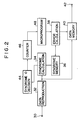
- Fig.2 is a block diagram showing the arrangement of the error correction circuit according to the embodiment of this invention.
- digital data code train
- a data reproduction circuit 32 causes the input data at the input terminal 30 to be subjected to demodulation, synchronous separation, ID recognition, and other processes to thereby reproduce each data (code) and output the reproduced data.
- This reproduced data is directly written in a data memory 40 in accordance with the recognized ID information, and is also applied to a syndrome calculation circuit 34 for error correction.
- the syndrome calculation circuit 34 executes a syndrome calculation for each error correction code constructed of a plurality of transmission codes, and sequentially writes a plurality of syndrome for each error correction code into a syndrome memory 36.
- the calculation results obtained by the syndrome calculation circuit 34 are also supplied to a syndrome 0 detection circuit 44.
- This circuit 44 judges whether the plurality of syndromes for each error correction code are all 0 or not.
- a counter 46 counts the number of error correction codes whose syndrome are not all 0, i.e., counts during a predetermined time duration the number of error correction codes having an error.
- the count value of the counter 46 at the predetermined time duration corresponds to the information representative of the transmission error rate.
- the counter 46 generates and outputs a mode selection signal for selecting an error correction algorithm to be described later.
- the mode selection signal it uses one bit information which takes a value 1 for the transmission error rate equal to or larger than a predetermined value, and 0 for the transmission error rate smaller than the predetermined value.
- An error position and error pattern calculation circuit 38 is constructed of a general arithmetic operation processing circuit, and is controlled by a microprogram generator 48. As will be described later, the microprogram generator 48 is provided with a plurality of program modules each having a different decoding algorithm. The error position and error pattern calculation circuit 38 is controlled by a module selected by a mode selection signal supplied from the counter 46. Specifically, the circuit 38 executes an error correction suitable for reproducing image data with less image deterioration, by using the optimum decoding algorithm for the current transmission error rate.
- the current error correction code is a two errors correctable code, and that two types of decoding modes for different transmission error rates have been set in the microprogram generator 48.
- the error position and error pattern calculation circuit 38 executes an error correction process, and executes not an error correction process but an uncorrectable error process if three or more error codes are generated.
- the error correction process means to calculate the error position and error pattern, and by using the calculated results, correct the error code in the data memory 40.
- the uncorrectable error process means to judge the error as uncorrectable, maintain unchanged the corresponding error correction code in the data memory 40, enter a correction flag indicative of a presence of an error in the data memory, and perform other necessary processes.
- the microprogram generator 48 selects a program module for a specific mode in accordance with a mode selection signal supplied thereto. For example, an error correction process is executed only if there is one error code in each error correction code, and an uncorrectable error process is executed if there are two error codes or more.
- a line 1 indicates the uncorrectable probability during the normal mode, i.e., during a mode for correcting up to two error codes
- a line 2 indicates the error correction probability during the normal mode
- a line 3 indicates the uncorrectable probability during the specific mode used with a bad error rate, i.e., during a mode for correcting only one error code
- a line 4 indicates the error correction probability during the specific mode.
- the uncorrectable probability increases, i.e., becomes bad
- the error correction probability becomes small. Accordingly, by using the normal mode while the error rate is small and the specific mode while it is large, the error correction probability can be restricted within an allowable range except a considerably large error rate.
- the error position and error pattern calculation circuit 38 reads syndromes written in the syndrome memory 36 to execute a decoding process for the error correction code. If all syndromes for the corresponding error correction code are 0, it is judged that there is no error to thereby terminate the processing for that code. On the other hand, all syndromes are not 0, there is an error and if the error is judged as correctable, the circuit 38 calculates the error position and error pattern, and using the calculated results, the code stored in the data memory is corrected. If the error is judged as uncorrectable, the corresponding code in the data memory is remained unchanged, a flag indicative of a presence of an error is entered in the data memory 40, and other necessary processes are executed.
- Fig.4 is a block diagram showing the arrangement of an error detection and correction device according to another embodiment of this invention. Like elements to those shown in Fig.2 are represented by identical reference numerals, and the description therefor is omitted.
- the present invention is applied to a digital VTR having a transmission path of a magnetic recording and reproducing system.
- T represents a magnetic tape
- Ha and Hb represent a rotary magnetic head.
- the rotary magnetic heads Ha and Hb alternately trace the magnetic tape T and alternately output a reproduced signal.
- a switch 31 selects the outputs of the heads Ha and Hb, and supplies it as the reproduced data (code train) to a data reproduction circuit 32.
- the VTR of this embodiment has two modes, one being the normal reproduction mode for running the magnetic tape T at the speed same as that during the recording, and the other being the specific reproduction mode for running the magnetic tape T at the speed different from that during the recording. These reproduction modes are selected by an operator from an operation unit 52.
- a system controller 50 outputs a mode setting signal to control the circuits of the device. Specifically, the system controller 50 supplies the mode setting signal to a capstan controller 54 to control a capstan C so that during the normal reproduction mode magnetic tape T is caused to run at the speed same as that during the recording, whereas during the specific reproduction mode, it is caused to run at a preset speed different from that during the recording.
- the system controller supplies the mode setting signal also to a microprogram generator 48 which selects a program for the normal mode during the normal reproduction mode, and a program for the specific mode during the specific reproduction mode.
- an error correction process is executed if there are two or less error codes, and an uncorrectable process is executed if there are three of more error codes.
- an error correction process is executed if there is one error code, and an uncorrectable process if there is three or more error codes.
- the tracing loci of the rotary heads Ha and Hb are generally parallel with the recorded helical track and the tracking control is executed. Therefore, there seldom occurs a high error code rate of a reproduced code train from the switch 31.
- the tracing loci of the rotary heads Ha and Hb intersect with the recorded helical track so that the error code rate of a reproduced code train becomes high.
- a normal error correction is executed during the normal reproduction mode, and an error correction capability is lowered during the specific reproduction mode to thereby make the error correction probability equal to or lower than a predetermined value.
- the embodiment device shown in Fig.4 has similar advantageous effects to the embodiment shown in Fig. 2.
- the embodiment device applied to a reproducing system can make the circuit for switching between the normal mode and specific mode considerably simple, as compared with the embodiment shown in Fig.2.
- Fig.5 is a block diagram showing the arrangement of an error detection and correction device according to a still further embodiment of this invention. Like elements to those shown in Fig.2 are represented by identical reference numerals, and the detailed description therefor is omitted.
- the embodiment shown in Fig.5 assumes to use as the correction coding system a so-called chain coding system which has as the error correction code so-called inner and outer codes.
- Reference numeral 35 represents a syndrome calculation circuit for an inner code, 37 a syndrome memory for an inner code, 39 an error calculation circuit for an inner code, 49 a microprogram generator for an inner code. These circuits perform, for an inner code, similar operations to those of the circuits 34, 36, 38 and 48 shown in Fig.2.
- Reference numeral 55 represents a syndrome calculation circuit for an outer code, 57 a syndrome memory for an outer code, 59 an error calculation circuit for an outer code, and 51 a microprogram generator for an outer code. These circuits perform, for an outer code, similar operations to those of the circuits 34, 36, 38 and 48 shown in Fig.2.
- the microprogram generator 49 for an inner code is always set at a normal mode.
- the results calculated by the syndrome calculation circuit 55 for an outer code are supplied to a syndrome 0 decision circuit lls to decide whether or not all of a plurality of syndromes for each outer code are 0.
- a counter 47 similar to the counter 46 shown in Fig.2, causes the microprogram generator 51 for an outer code to select a program module which performs an error correction process if there are two or less error codes and performs an uncorrectable process if there are three or more error codes, respectively when the number of outer codes with error is equal to or smaller than a predetermined threshold value during a predetermined time duration.
- the counter also causes the microprogram generator 51 for an outer code to select a program module which always performs not an error correction process but an uncorrectable process when the number of outer codes with error exceeds the predetermined threshold value.
- a sufficient error correction is executed if the error code rate is low, and another error correction process for an outer code is executed if the error code rate is high. Namely, if the error code rate is high, the error correction capability is lowered as a whole to restrict the occurrence of error corrections equal to or lower than a predetermined value, to thereby prevent large deterioration of the reproduced data (code train).
- the microprogram generator 51 for an outer code selects a program module for executing another process. For instance, advantageous effects can be obtained by selecting a program module which executes an error correction process only when there is one error code and executes an uncorrectable process which there are two or more error codes.
Landscapes
- Engineering & Computer Science (AREA)
- Physics & Mathematics (AREA)
- Probability & Statistics with Applications (AREA)
- Theoretical Computer Science (AREA)
- Signal Processing (AREA)
- Error Detection And Correction (AREA)
- Detection And Prevention Of Errors In Transmission (AREA)
Claims (13)
- Einrichtung zur Fehlererfassung und Fehlerkorrektur, mita) einer Eingabeeinrichtung (32) zur Eingabe einer Codefolge, die eine Anzahl von Fehlerkorrekturcodes enthält, die jeweils aus einer Vielzahl von Codes bestehen;b) einer Fehlerkorrektureinrichtung (38, 59) zur Korrektur von fehlerhaften Codes unter Verwendung eines Fehlerkorrekturcodes innerhalb der Codefolge; undc) einer Auswahleinrichtung (48, 51) zur Auswahl einer Betriebsart aus einer Vielzahl von erste und zweite Betriebsarten umfassenden Betriebsarten als die Funktionsbetriebsart der Fehlerkorrektureinrichtung (38, 59), wobei die zweite Betriebsart ausgewählt wird, wenn eine die Anzahl fehlerhafter Codes der Codefolge wiedergebende Fehlerinformation einen vorbestimmten Wert überschreitet, und die erste Betriebsart ausgewählt wird, wenn die Fehlerinformation kleiner als der vorbestimmte Wert ist;dadurch gekennzeichnet, daß
es sich bei der ersten Betriebsart um eine Betriebsart handelt, bei der eine Fehlerkorrektur erfolgt, wenn die Anzahl der fehlerhaften Codes kleiner als oder gleich m ist, und bei der sonst keine Fehlerkorrektur erfolgt, und es sich bei der zweiten Betriebsart um eine Betriebsart handelt, bei der eine Fehlerkorrektur erfolgt, wenn die Anzahl der fehlerhaften Codes kleiner als oder gleich n ist, und bei der sonst keine Fehlerkorrektur erfolgt, wobei m und n unterschiedliche von Null verschiedene natürliche Zahlen sind, und wobei m größer als n ist, und die erste und die zweite Betriebsart den jeweils selben Fehlerkorrekturcode verwenden. - Einrichtung nach Anspruch 1,
gekenzeichnet durch
eine Erfassungseinrichtung (44, 46, 45, 47) zur Erfassung von die Anzahl fehlerhafter Codes der Codefolge wiedergebenden Fehlerinformation, wobei die Auswahleinrichtung (48) die erste und die zweite Betriebsart entsprechend einem Ausgangssignal der Erfassungseinrichtung (44, 46, 45, 47) auswählt. - Einrichtung nach Anspruch 1 oder 2,
dadurch gekennzeichnet, daß
der Fehlerkorrekturcode derart beschaffen ist, daß mit jedem Fehlerkorrekturcode zwei fehlerhafte Codes korrigiert werden können, und die Fehlerkorrektureinrichtung (38) eine Fehlerkorrekturverarbeitung in der ersten Betriebsart ausführt, wenn es zwei oder weniger fehlerhafte Codes bei jedem Fehlerkorrekturcode gibt, und eine Fehlerkorrekturverarbeitung in der zweiten Betriebsart ausführt, wenn es nur einen fehlerhaften Code bei jedem Fehlerkorrekturcode gibt. - Einrichtung nach Anspruch 1 oder 2,
dadurch gekennzeichnet, daß
der Fehlerkorrekturcode erste und zweite Fehlerkorrekturcodes umfaßt. - Einrichtung nach Anspruch 4,
dadurch gekennzeichnet, daß
es sich bei dem ersten Fehlerkorrekturcode um einen Code handelt, der an einem äußereren Teil einer Übertragungsstrekke der Codefolge als der zweite Fehlerkorrekturcode kodiert und dekodiert wird. - Einrichtung nach Anspruch 2,
dadurch gekennzeichnet, daß
die Erfassungseinrichtung (44, 46, 45, 47) eine Erfassungsschaltung (44, 45) zur Erfassung des Vorhandenseins oder des Fehlens eines fehlerhaften Codes in jedem Fehlerkorrekturcode gemäß einer Vielzahl von Merkmalsgruppen für jeden Fehlerkorrekturcode aufweist. - Einrichtung nach Anspruch 6,
dadurch gekennzeichnet, daß
die Erfassungsschaltung (44, 45) erfaßt, ob alle der Vielzahl von Merkmalsgruppen Null sind. - Einrichtung nach Anspruch 6,
dadurch gekennzeichnet, daß
die Erfassungseinrichtung (44, 46, 45, 47) eine Zählerschaltung (46, 47) zum Zählen der Anzahl von einen fehlerhaften Code aufweisenden Fehlererfassungscodes während einer vorbestimmten Zeitdauer unter Verwendung eines Erfassungsausgangssignals der Erfassungsschaltung (44, 45) umfaßt. - Einrichtung nach Anspruch 1,
dadurch gekennzeichnet, daßdie Eingabeeinrichtung einen Wiedergabekopf (Ha, Hb) zur Wiedergabe der Codefolge von einer Anzahl von auf einem Bandaufzeichnungsträger (T) ausgebildeten helikalen Spuren aufweist, wobei die Einrichtung zudem aufweist:eine Erzeugungseinrichtung (50) zur Erzeugung einer der Anzahl fehlerhafter Codes der Codefolge zugeordneten die Betriebsart einstellenden Information;eine Transporteinrichtung (54, C) zum Transport des Bandaufzeichnungsträgers (T), wobei die Transporteinrichtung (54, C) als Transportgeschwindigkeit des Bandaufzeichnungsträgers (T) aus einer Vielzahl von erste und zweite Geschwindigkeiten umfassenden Geschwindigkeiten, entsprechend der die Betriebsart einstellenden Information von der Erzeugungseinrichtung (50) auswählt, wobei der Wiedergabekopf (Ha, Hb) dem Bandaufzeichnungsträger (T) im wesentlichen parallel zur Längsrichtung der helikalen Spur folgt, wenn der Bandaufzeichnungsträger (T) mit der ersten Geschwindigkeit transportiert wird, und der Wiedergabekopf (Ha, Hb) dem Bandaufzeichnungsträger (T) in der die Längsrichtung der helikalen Spur kreuzenden Richtung folgt, wenn der Bandaufzeichnungsträger (T) mit der zweiten Geschwindigkeit transportiert wird. - Einrichtung nach Anspruch 9,
dadurch gekennzeichnet, daß
die Auswahleinrichtung (48, 51) die erste Betriebsart auswählt, wenn die Transporteinrichtung den Bandaufzeichnungsträger (T) mit der ersten Geschwindigkeit transportiert, und die zweite Betriebsart auswählt, wenn die Transporteinrichtung den Bandaufzeichnungsträger (T) mit der zweiten Geschwindigkeit transportiert. - Einrichtung nach Anspruch 1,
dadurch gekennzeichnet, daß
die Eingabeeinrichtung (32) einen Wiedergabekopf (Ha, Hb) zur Wiedergabe der Codefolge von einem Bandaufzeichnungsträger (T) umfaßt. - Einrichtung nach Anspruch 11,
gekennzeichnet durch
eine Einstelleinrichtung zur Einstellung einer Wiedergabebetriebsart des Wiedergabekopfs, wobei die Auswahleinrichtung die ersten und die zweiten Betriebsarten der Fehlerkorrektureinrichtung gemäß einem Ausgangssignal der Einstelleinrichtung auswählt. - Verfahren zur Fehlererfassung und Fehlerkorrektur mit den Schritten:Eingeben einer Codefolge mit einer Anzahl von jeweils aus einer Vielzahl von Codes bestehenden Fehlerkorrekturcodes über eine Übertragungsstrecke,Korrigieren von fehlerhaften Codes unter Verwendung des Fehlerkorrekturcodes innerhalb der Codefolge, undAuswählen einer Betriebsart aus einer Vielzahl von erste und zweite Betriebsarten umfassenden Betriebsarten als die Funktionsbetriebsart der Fehlerkorrektureinrichtung, wobei die zweite Betriebsart ausgewählt wird, wenn eine die Anzahl fehlerhafter Codes der Codefolge wiedergebende Fehlerinformation einen vorbestimmten Wert überschreitet, und die erste Betriebsart ausgewählt wird, wenn die Fehlerinformation kleiner als der vorbestimmte Wert ist;gekennzeichnet durch die Schritte:
Korrigieren der fehlerhaften Codes in der ersten Betriebsart, wenn die Anzahl der fehlerhaften Codes kleiner als oder gleich m ist, und bei der sonst keine Fehlerkorrektur erfolgt, und Korrigieren der fehlerhaften Codes in der zweiten Betriebsart, wenn die Anzahl der fehlerhaften Codes kleiner als oder gleich n ist, und bei der sonst keine Fehlerkorrektur erfolgt, wobei m und n unterschiedliche von Null verschiedene natürliche Zahlen sind, und wobei m größer als n ist, und die erste und die zweite Betriebsart den jeweils selben Fehlerkorrekturcode verwenden.
Applications Claiming Priority (2)
| Application Number | Priority Date | Filing Date | Title |
|---|---|---|---|
| JP144530/89 | 1989-06-07 | ||
| JP01144530A JP3137119B2 (ja) | 1989-06-07 | 1989-06-07 | 誤り訂正装置 |
Publications (3)
| Publication Number | Publication Date |
|---|---|
| EP0402115A2 EP0402115A2 (de) | 1990-12-12 |
| EP0402115A3 EP0402115A3 (de) | 1991-06-26 |
| EP0402115B1 true EP0402115B1 (de) | 1997-08-20 |
Family
ID=15364464
Family Applications (1)
| Application Number | Title | Priority Date | Filing Date |
|---|---|---|---|
| EP90306151A Expired - Lifetime EP0402115B1 (de) | 1989-06-07 | 1990-06-06 | Einrichtung und Verfahren zur Fehlererkennung und Fehlerkorrektur |
Country Status (4)
| Country | Link |
|---|---|
| US (2) | US5687182A (de) |
| EP (1) | EP0402115B1 (de) |
| JP (1) | JP3137119B2 (de) |
| DE (1) | DE69031294T2 (de) |
Cited By (4)
| Publication number | Priority date | Publication date | Assignee | Title |
|---|---|---|---|---|
| US5436917A (en) * | 1992-05-18 | 1995-07-25 | Canon Kabushiki Kaisha | Data processing apparatus having error detection/correction codes |
| US5784356A (en) * | 1995-10-27 | 1998-07-21 | Kabushiki Kaisha Toshiba | Optical disk reproducing apparatus equipped with variable gain amplifier capable of adjusting amplitude of reproduction signal |
| EP0730795B1 (de) * | 1993-11-22 | 2003-02-19 | Thomson Consumer Electronics, Inc. | Schaltgerät für satellitenempfängercoderate |
| US6564343B1 (en) | 1999-02-19 | 2003-05-13 | Fujitsu Limited | Bit interleave circuit and bit deinterleave circuit |
Families Citing this family (34)
| Publication number | Priority date | Publication date | Assignee | Title |
|---|---|---|---|---|
| JPH03166826A (ja) * | 1989-11-25 | 1991-07-18 | Victor Co Of Japan Ltd | 誤り検出訂正装置 |
| JPH06104773A (ja) * | 1992-07-20 | 1994-04-15 | Internatl Business Mach Corp <Ibm> | 線形代数符号のキー式の解を求めるためのプログラム可能な逐次形キー式求解回路及び方法 |
| KR19990071860A (ko) * | 1996-09-30 | 1999-09-27 | 이데이 노부유끼 | 재생장치,에러정정장치,및에러정정방법 |
| US5974580A (en) * | 1997-07-23 | 1999-10-26 | Cirrus Logic, Inc. | Concurrent row/column syndrome generator for a product code |
| JPH1166762A (ja) * | 1997-08-08 | 1999-03-09 | Alps Electric Co Ltd | フロッピディスクシステム |
| US6457156B1 (en) * | 1998-01-29 | 2002-09-24 | Adaptec, Inc. | Error correction method |
| US6272659B1 (en) * | 1998-05-18 | 2001-08-07 | Cirrus Logic, Inc. | Error correction code processor employing adjustable correction power for miscorrection minimization |
| US6308298B1 (en) * | 1998-11-16 | 2001-10-23 | Ecrix Corporation | Method of reacquiring clock synchronization on a non-tracking helical scan tape device |
| JP2000251419A (ja) * | 1999-02-26 | 2000-09-14 | Sony Corp | 読み出し制御装置、再生装置、記録装置およびその方法 |
| US6405340B1 (en) * | 1999-07-02 | 2002-06-11 | Ericsson Inc. | Flexible method of error protection in communications systems |
| JP3450756B2 (ja) * | 1999-09-08 | 2003-09-29 | 松下電器産業株式会社 | 誤り訂正方法および誤り訂正装置 |
| US6662335B1 (en) * | 2000-01-25 | 2003-12-09 | Mediatek Inc. | Method and apparatus for accessing DVD data |
| JP3352659B2 (ja) * | 2000-03-27 | 2002-12-03 | 松下電器産業株式会社 | 復号装置及び復号方法 |
| KR20020065788A (ko) * | 2001-02-07 | 2002-08-14 | 삼성전자 주식회사 | 엠 또는 이엠 비트 데이터 처리 겸용 리드 솔로몬 복호기및 그 복호 방법 |
| US7290184B2 (en) * | 2001-08-23 | 2007-10-30 | Seagate Technology Llc | Emulation system for evaluating digital data channel configurations |
| EP1569348A1 (de) * | 2004-02-13 | 2005-08-31 | Alcatel | Multidimensionale iterative Dekodierung |
| US7707588B2 (en) * | 2004-03-02 | 2010-04-27 | Avicode, Inc. | Software application action monitoring |
| US20070260961A1 (en) * | 2006-04-21 | 2007-11-08 | Kuo-Lung Chien | Error correction system and related method thereof |
| US20070260960A1 (en) * | 2006-04-21 | 2007-11-08 | Kuo-Lung Chien | Error correction system and related method thereof |
| US20070260963A1 (en) * | 2006-04-21 | 2007-11-08 | Kuo-Lung Chien | Error correction system and related method thereof |
| US8964831B2 (en) | 2007-05-16 | 2015-02-24 | Thomson Licensing | Apparatus and method for encoding and decoding signals |
| US20090070655A1 (en) * | 2007-09-11 | 2009-03-12 | Silicon Motion, Inc. | Method for Generating an ECC Code for a Memory Device |
| KR101532315B1 (ko) | 2007-10-15 | 2015-06-30 | 톰슨 라이센싱 | 모바일 역량을 지닌 고선명 텔레비전 송신 |
| KR101513283B1 (ko) | 2007-10-15 | 2015-04-17 | 톰슨 라이센싱 | 버스트 모드 활동을 통신하기 위한 장치 및 방법 |
| US9104794B2 (en) * | 2008-07-15 | 2015-08-11 | Microsoft Technology Licensing, Llc | Automatic incremental application dependency discovery through code instrumentation |
| US8051332B2 (en) | 2008-07-15 | 2011-11-01 | Avicode Inc. | Exposing application performance counters for .NET applications through code instrumentation |
| US8296620B2 (en) * | 2008-08-26 | 2012-10-23 | Seagate Technology Llc | Data devices including multiple error correction codes and methods of utilizing |
| US9323609B2 (en) * | 2013-11-15 | 2016-04-26 | Intel Corporation | Data storage and variable length error correction information |
| US9983972B2 (en) | 2015-06-01 | 2018-05-29 | Cisco Technology, Inc. | Predictive in-field memory repair scheme |
| US10140180B1 (en) * | 2016-11-04 | 2018-11-27 | Seagate Technology Llc | Segment-based outer code recovery |
| US10177791B1 (en) * | 2016-11-08 | 2019-01-08 | Seagate Technology Llc | Syndrome update and maintenance |
| US10831596B2 (en) * | 2018-01-22 | 2020-11-10 | Micron Technology, Inc. | Enhanced error correcting code capability using variable logical to physical associations of a data block |
| DE102022111623A1 (de) * | 2022-05-10 | 2023-11-16 | Infineon Technologies Ag | Fehlerkorrektur mit schneller Syndromberechnung |
| DE102022111624B4 (de) | 2022-05-10 | 2024-06-13 | Infineon Technologies Ag | Fehlerkorrektur mit schneller Syndromberechnung |
Citations (1)
| Publication number | Priority date | Publication date | Assignee | Title |
|---|---|---|---|---|
| EP0136604A2 (de) * | 1983-09-14 | 1985-04-10 | Matsushita Electric Industrial Co., Ltd. | Dekodierverfahren und Vorrichtung dafür. |
Family Cites Families (19)
| Publication number | Priority date | Publication date | Assignee | Title |
|---|---|---|---|---|
| US3078443A (en) * | 1959-01-22 | 1963-02-19 | Alan C Rose | Compound error correction system |
| US3638182A (en) * | 1970-01-02 | 1972-01-25 | Bell Telephone Labor Inc | Random and burst error-correcting arrangement with guard space error correction |
| US4404673A (en) * | 1981-02-09 | 1983-09-13 | National Semiconductor Corporation | Error correcting network |
| NL8200207A (nl) * | 1982-01-21 | 1983-08-16 | Philips Nv | Werkwijze met foutkorrektie voor het overdragen van blokken databits, een inrichting voor het uitvoeren van een dergelijke werkwijze, een dekodeur voor gebruik bij een dergelijke werkwijze, en een inrichting bevattende een dergelijke dekodeur. |
| US4541091A (en) * | 1982-06-11 | 1985-09-10 | Hitachi, Ltd. | Code error detection and correction method and apparatus |
| GB2126760B (en) * | 1982-08-20 | 1985-08-29 | Sony Corp | Error correction of digital television signals |
| JPS59200547A (ja) * | 1983-04-26 | 1984-11-13 | Nec Corp | 回線品質監視方式 |
| JPS59228440A (ja) * | 1983-06-09 | 1984-12-21 | Fujitsu Ltd | デ−タ伝送方式 |
| ATE78383T1 (de) * | 1985-05-21 | 1992-08-15 | Sony Corp | Anordnung zur dekodierung eines fehler korrigierenden codes. |
| DE3776161D1 (de) * | 1986-03-04 | 1992-03-05 | Sony Corp | Digitalwiedergabegeraet. |
| EP0566215B1 (de) * | 1986-09-30 | 1996-11-20 | Canon Kabushiki Kaisha | Fehlerkorrekturgerät |
| US4953019A (en) * | 1987-11-27 | 1990-08-28 | Canon Kabushiki Kaisha | Image signal encoding apparatus |
| US5070503A (en) * | 1988-03-09 | 1991-12-03 | Canon Kabushiki Kaisha | Digital information transmitting and receiving system |
| US4866719A (en) * | 1988-03-21 | 1989-09-12 | Sony Corporation | System and method for performing error correction on still frame audio tape format video signals |
| JP2638091B2 (ja) * | 1988-06-24 | 1997-08-06 | ソニー株式会社 | データ伝送方法 |
| US5068855A (en) * | 1988-07-18 | 1991-11-26 | Canon Kabushiki Kaisha | Error correcting method and apparatus |
| US4979174A (en) * | 1988-12-29 | 1990-12-18 | At&T Bell Laboratories | Error correction and detection apparatus and method |
| US5212695A (en) * | 1989-04-28 | 1993-05-18 | Canon Kabushiki Kaisha | Error check or erro correction code coding device |
| JP2751415B2 (ja) | 1989-06-07 | 1998-05-18 | キヤノン株式会社 | 誤り検出訂正回路 |
-
1989
- 1989-06-07 JP JP01144530A patent/JP3137119B2/ja not_active Expired - Lifetime
-
1990
- 1990-06-06 DE DE69031294T patent/DE69031294T2/de not_active Expired - Fee Related
- 1990-06-06 EP EP90306151A patent/EP0402115B1/de not_active Expired - Lifetime
-
1994
- 1994-12-14 US US08/355,986 patent/US5687182A/en not_active Expired - Lifetime
-
1997
- 1997-07-17 US US08/895,819 patent/US5996109A/en not_active Expired - Fee Related
Patent Citations (1)
| Publication number | Priority date | Publication date | Assignee | Title |
|---|---|---|---|---|
| EP0136604A2 (de) * | 1983-09-14 | 1985-04-10 | Matsushita Electric Industrial Co., Ltd. | Dekodierverfahren und Vorrichtung dafür. |
Non-Patent Citations (1)
| Title |
|---|
| & JP-A- 59 200547 * |
Cited By (4)
| Publication number | Priority date | Publication date | Assignee | Title |
|---|---|---|---|---|
| US5436917A (en) * | 1992-05-18 | 1995-07-25 | Canon Kabushiki Kaisha | Data processing apparatus having error detection/correction codes |
| EP0730795B1 (de) * | 1993-11-22 | 2003-02-19 | Thomson Consumer Electronics, Inc. | Schaltgerät für satellitenempfängercoderate |
| US5784356A (en) * | 1995-10-27 | 1998-07-21 | Kabushiki Kaisha Toshiba | Optical disk reproducing apparatus equipped with variable gain amplifier capable of adjusting amplitude of reproduction signal |
| US6564343B1 (en) | 1999-02-19 | 2003-05-13 | Fujitsu Limited | Bit interleave circuit and bit deinterleave circuit |
Also Published As
| Publication number | Publication date |
|---|---|
| EP0402115A3 (de) | 1991-06-26 |
| JP3137119B2 (ja) | 2001-02-19 |
| DE69031294D1 (de) | 1997-09-25 |
| JPH0310422A (ja) | 1991-01-18 |
| DE69031294T2 (de) | 1997-12-18 |
| US5996109A (en) | 1999-11-30 |
| EP0402115A2 (de) | 1990-12-12 |
| US5687182A (en) | 1997-11-11 |
Similar Documents
| Publication | Publication Date | Title |
|---|---|---|
| EP0402115B1 (de) | Einrichtung und Verfahren zur Fehlererkennung und Fehlerkorrektur | |
| EP0571096B1 (de) | Datenverarbeitungsvorrichtung | |
| EP0217292B1 (de) | Verfahren zur Kode-Fehlerkorrektur | |
| US5247523A (en) | Code error correction apparatus | |
| US4972416A (en) | Error detection and correction method | |
| JPH0520105A (ja) | デジタルデータのエラー訂正装置 | |
| JP2558994B2 (ja) | デジタル画像信号の誤り補正方法及び誤り補正装置 | |
| US6522831B2 (en) | Reproducing apparatus | |
| US6047398A (en) | Reproducing method, reproducing apparatus and recording and reproducing apparatus using the same reproducing method, and recording medium having the same method recorded therein | |
| JPH0634313B2 (ja) | エラ−訂正方法 | |
| JP2574740B2 (ja) | Pcm信号再生装置 | |
| KR100223821B1 (ko) | 디지탈 비데오 디스크 시스템의 에러정정 회로 및 방법 | |
| JP3210002B2 (ja) | 誤り訂正装置 | |
| JP3277062B2 (ja) | 誤り訂正符号の復号装置 | |
| JP2751415B2 (ja) | 誤り検出訂正回路 | |
| JP2924017B2 (ja) | ビデオ信号処理回路 | |
| KR0160603B1 (ko) | 오류발생형태 적응형 오류정정장치 | |
| JPH0628343B2 (ja) | 積符号の復号方法 | |
| JP3302183B2 (ja) | トラッキング制御装置 | |
| JPH05328290A (ja) | データ再生処理回路 | |
| JPH0831114A (ja) | ディジタル情報記録再生装置 | |
| JPS63187471A (ja) | ディジタルデータ記録装置及び記録再生装置 | |
| JPS6366097B2 (de) | ||
| JPH0442621A (ja) | 誤り検出訂正回路 | |
| JPH08329622A (ja) | データ再生装置 |
Legal Events
| Date | Code | Title | Description |
|---|---|---|---|
| PUAI | Public reference made under article 153(3) epc to a published international application that has entered the european phase |
Free format text: ORIGINAL CODE: 0009012 |
|
| AK | Designated contracting states |
Kind code of ref document: A2 Designated state(s): DE ES FR GB IT NL |
|
| 17P | Request for examination filed |
Effective date: 19901231 |
|
| PUAL | Search report despatched |
Free format text: ORIGINAL CODE: 0009013 |
|
| AK | Designated contracting states |
Kind code of ref document: A3 Designated state(s): DE ES FR GB IT NL |
|
| 17Q | First examination report despatched |
Effective date: 19930927 |
|
| GRAG | Despatch of communication of intention to grant |
Free format text: ORIGINAL CODE: EPIDOS AGRA |
|
| GRAH | Despatch of communication of intention to grant a patent |
Free format text: ORIGINAL CODE: EPIDOS IGRA |
|
| GRAH | Despatch of communication of intention to grant a patent |
Free format text: ORIGINAL CODE: EPIDOS IGRA |
|
| GRAA | (expected) grant |
Free format text: ORIGINAL CODE: 0009210 |
|
| AK | Designated contracting states |
Kind code of ref document: B1 Designated state(s): DE ES FR GB IT NL |
|
| PG25 | Lapsed in a contracting state [announced via postgrant information from national office to epo] |
Ref country code: IT Free format text: LAPSE BECAUSE OF FAILURE TO SUBMIT A TRANSLATION OF THE DESCRIPTION OR TO PAY THE FEE WITHIN THE PRE;WARNING: LAPSES OF ITALIAN PATENTS WITH EFFECTIVE DATE BEFORE 2007 MAY HAVE OCCURRED AT ANY TIME BEFORE 2007. THE CORRECT EFFECTIVE DATE MAY BE DIFFERENT FROM THE ONE RECORDED.SCRIBED TIME-LIMIT Effective date: 19970820 Ref country code: ES Free format text: THE PATENT HAS BEEN ANNULLED BY A DECISION OF A NATIONAL AUTHORITY Effective date: 19970820 |
|
| REF | Corresponds to: |
Ref document number: 69031294 Country of ref document: DE Date of ref document: 19970925 |
|
| ET | Fr: translation filed | ||
| PLBE | No opposition filed within time limit |
Free format text: ORIGINAL CODE: 0009261 |
|
| STAA | Information on the status of an ep patent application or granted ep patent |
Free format text: STATUS: NO OPPOSITION FILED WITHIN TIME LIMIT |
|
| 26N | No opposition filed | ||
| REG | Reference to a national code |
Ref country code: GB Ref legal event code: IF02 |
|
| PGFP | Annual fee paid to national office [announced via postgrant information from national office to epo] |
Ref country code: DE Payment date: 20080630 Year of fee payment: 19 Ref country code: NL Payment date: 20080618 Year of fee payment: 19 |
|
| PGFP | Annual fee paid to national office [announced via postgrant information from national office to epo] |
Ref country code: FR Payment date: 20080625 Year of fee payment: 19 |
|
| PGFP | Annual fee paid to national office [announced via postgrant information from national office to epo] |
Ref country code: GB Payment date: 20080627 Year of fee payment: 19 |
|
| GBPC | Gb: european patent ceased through non-payment of renewal fee |
Effective date: 20090606 |
|
| NLV4 | Nl: lapsed or anulled due to non-payment of the annual fee |
Effective date: 20100101 |
|
| REG | Reference to a national code |
Ref country code: FR Ref legal event code: ST Effective date: 20100226 |
|
| PG25 | Lapsed in a contracting state [announced via postgrant information from national office to epo] |
Ref country code: FR Free format text: LAPSE BECAUSE OF NON-PAYMENT OF DUE FEES Effective date: 20090630 |
|
| PG25 | Lapsed in a contracting state [announced via postgrant information from national office to epo] |
Ref country code: GB Free format text: LAPSE BECAUSE OF NON-PAYMENT OF DUE FEES Effective date: 20090606 |
|
| PG25 | Lapsed in a contracting state [announced via postgrant information from national office to epo] |
Ref country code: DE Free format text: LAPSE BECAUSE OF NON-PAYMENT OF DUE FEES Effective date: 20100101 |
|
| PG25 | Lapsed in a contracting state [announced via postgrant information from national office to epo] |
Ref country code: NL Free format text: LAPSE BECAUSE OF NON-PAYMENT OF DUE FEES Effective date: 20100101 |