EP0402413B1 - Racleur de bande de manutention - Google Patents
Racleur de bande de manutention Download PDFInfo
- Publication number
- EP0402413B1 EP0402413B1 EP89904106A EP89904106A EP0402413B1 EP 0402413 B1 EP0402413 B1 EP 0402413B1 EP 89904106 A EP89904106 A EP 89904106A EP 89904106 A EP89904106 A EP 89904106A EP 0402413 B1 EP0402413 B1 EP 0402413B1
- Authority
- EP
- European Patent Office
- Prior art keywords
- wear element
- pressure
- seal
- opening
- further characterised
- Prior art date
- Legal status (The legal status is an assumption and is not a legal conclusion. Google has not performed a legal analysis and makes no representation as to the accuracy of the status listed.)
- Expired - Lifetime
Links
Images


Classifications
-
- B—PERFORMING OPERATIONS; TRANSPORTING
- B65—CONVEYING; PACKING; STORING; HANDLING THIN OR FILAMENTARY MATERIAL
- B65G—TRANSPORT OR STORAGE DEVICES, e.g. CONVEYORS FOR LOADING OR TIPPING, SHOP CONVEYOR SYSTEMS OR PNEUMATIC TUBE CONVEYORS
- B65G45/00—Lubricating, cleaning, or clearing devices
- B65G45/10—Cleaning devices
- B65G45/12—Cleaning devices comprising scrapers
-
- B—PERFORMING OPERATIONS; TRANSPORTING
- B65—CONVEYING; PACKING; STORING; HANDLING THIN OR FILAMENTARY MATERIAL
- B65G—TRANSPORT OR STORAGE DEVICES, e.g. CONVEYORS FOR LOADING OR TIPPING, SHOP CONVEYOR SYSTEMS OR PNEUMATIC TUBE CONVEYORS
- B65G45/00—Lubricating, cleaning, or clearing devices
- B65G45/10—Cleaning devices
- B65G45/12—Cleaning devices comprising scrapers
- B65G45/16—Cleaning devices comprising scrapers with scraper biasing means
Definitions
- One type comprises a scraper element made of a block of rubber about a foot long and of a width conforming to the width of the conveyor belt, which is urged against the moving belt by a hinge and counter-weight arrangement.
- the scraper blade is connected to an arm which is urged against the conveyor belt by a torque applying mechanism such as a spring steel arm or air cylinder.
- the scraper blade is biassed towards the conveyor belt by means of a coil spring.
- the conveyor belt cleaning device disclosed in US 4290520 avoids the need for independent suspension springs or other mechanical adjustments of the mounting of the scraper blade by utilizing a pressurized air bag.
- the use of this design limits the length of the scraper blade since the scraper unit must be compact in order to fit into the space provided in typical conveyor chutes.
- the RHODES conveyor scraper also entails relatively high maintenace costs, caused by relatively frequent service intervals, as well as a high percentage of waste by volume of the wear element.
- the applicant has found that the disadvantages of the prior art can be overcome by apparatus adapted to apply compressed air or other fluid directly on to a relatively lengthy wear element, which is coiled or otherwise stored in a scraper housing.
- the apparatus of the present invention is compact and contains no mechanical parts in its blade dispenser. It has the capability of dispensing a relatively long scraper element, which entails very little wastage.
- the scraper of the present invention is expected to significantly reduce maintenance costs (both parts and labour) as compared to known prior art scrapers.
- the arrangement of the present invention functions to naintain a suitable pressure between the scraper wear element and the conveyor belt. Moreover, by varying the pressure inside the housing, optimum scraping/wear ratios can be obtained.
- the present invention is directed to apparatus for removing particulate material from a conveyor belt, comprising a flexible wear element and a housing.
- the wear element bears against the working surface of a moving conveyor belt and removes particulate material therefrom.
- the housing is shaped and dimensioned for dispensing one end of the wear element against the conveyor belt and for storing the rest of the wear element within the interior of the housing.
- the housing is pressure-tight up to a given operating pressure, when the wear element is within the housing.
- the housing is adapted to be filled by a fluid (i.e. a gas such as air or a liquid such as water) which when compressed acts directly on the wear element within the housing to force the wear element against the conveyor belt and to maintain the wear element against the conveyor belt as the wear element wears.
- a fluid i.e. a gas such as air or a liquid such as water
- the housing comprises dispensing means for dispensing one end of the wear element against the conveyor belt and a storage chamber configured to store the rest of the wear element within the interior of the housing, preferably in a coiled fashion.
- the dispensing means includes sealing means for pressure sealing the interface between the interior of the housing and the wear element so that the housing is substantially pressure-tight.
- the sealing means preferably takes the form of a floating double lip pressure seal.
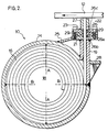
- conveyor scraper 10 comprises housing 14 and wear element 16.
- Housing 14 includes a storage chamber 18 and dispensing means 22.
- Wear element 16 is adapted to be stored in storage chamber 18 and dispensed through dispensing means 22.
- Housing 14 has a closed end 15 and an open end 17 which is adapted to be sealed in a pressure-tight fashion by access flange 24, which may take the form of a Victaulic (trademark) coupling.
- Storage chamber 18 is preferably made from a section of large diameter metal pipe of sufficient strength to withstand suitable operating pressures, which may range up to 100 psi (690 kN/sm) or more.
- Dispensing means 22 of housing 14 comprises a lower section 19 welded to storage portion 18, seal flange 21 welded onto the top of lower section 19, removable seal retainer plate 23, and top section 27.
- Lower section 19 has a slot therein for receiving wear element 16.
- Seal flange 21 includes a cavity for receiving pressure sealing means in the form of a lip seal 26 which seals off storage chamber 18 of housing 14 from the outside when wear element is within the slot of dispensing means 22.
- Seal retainer plate 23 includes a cavity for receiving lip seal 26, and is designed to be coupled to seal flange 21 by a plurality of cap screws 29.
- Top section 27 is welded onto the top of seal retainer 23, and is provided with a dispensing slot which is in alignment with the slot of lower section 19 when seal retainer 23 is screwed in place.
- Lip seal 26 is a continous seal which extends around the entire periphery of the dispensing slot.
- Lip seal 26 comprises a body portion 26a which is clamped securely between seal flange 21 and seal retainer 23, inside pressure sealing lip 26b and outside dust and water sealing lip 26c.
- Reinforcement members 25 and 28 provide dispensing means 22 with sufficient structural rigidity to prevent it from flexing when housing 14 is pressurized.
- Lip seal 26 is preferably made from polyurethane, but other materials, such as rubber, could be used.
- Wear element 16 is a sheet of flexible material capable of being stored in the storage chamber 18 of housing 14, preferably in a coiled fashion. Wear element 16 is preferably made from a polyurethane, such Thompson Gordon Thor-Flex 109H - A, which has been found to provide good scraping action without damage to the conveyor belt surface, and long wear life. As shown in Fig 1, the edges 32 of wear element 16 have rounded corners which mate with the corners of lip seal 26 in a pressure-tight fashion.
- wear element 16 will vary, depending upon the applications, but just to give one example, a 1/4 inch (6mm) thick polyurethane wear element having a width of 32 inches (81cm) and a length of approximately 118 inches (3m) may be stored in a storage chamber having a diameter of 8 inches (20cm), and has been found to be suitable for a number of conveyor applications.
- a 1/4 inch (6mm) thick polyurethane wear element having a width of 32 inches (81cm) and a length of approximately 118 inches (3m) may be stored in a storage chamber having a diameter of 8 inches (20cm), and has been found to be suitable for a number of conveyor applications.
- housing 14 Closed end 15 of housing 14 is provided with an air inlet valve 34, to allow housing 14 to be filled with compressed air.
- Housing 14 is pressure-tight up to a suitable internal operating pressure, when open end 17 is sealed by access flange 24 and wear element 16 is within lip seal 26, and housing 14 is filled with a compressed fluid, such as air, and here it should be understood that the term "fluid” refers to both gases and liquids.
- a compressed fluid such as air
- An internal operating air pressures of 20-100 psi (138-690 kN/sm) has been found to be suitable, but higher or lower pressures may be appropriate, depending upon the desired scraping pressure.
- the transverse dimensions A and B of storage chamber 18 are selected to be less than the length of wear element 16, so as to result in a relatively compact scraper capable of storing a relatively long wear element in a coiled fashion.
- the inside surface of storage chamber 18 is cylindrical, in which case the aforesaid transverse dimensions A and B would of course represent the inside diameter of the cylinder, but housings having inside surfaces of non-cylindrical geometry could also be used.
- conveyor scraper 10 is mounted in its working position adjacent conveyor belt 12, as shown in Fig 2 (the arrow represents the direction of conveyor belt travel) such that wear element 16 extends across the width of the conveyor belt.
- Housing 14 is then pressurized by compressed air from an outside source, through a pressure regulating valve up to a suitable internal operating pressure (which as discussed above may be 100 psi (690 kN/sm) or more).
- a 100 psi pressure produces a force of up to 800 pounds (3560 N) on a 1/4 inch (6mm) by 32 inch (81cm) wear element.
- the compressed air inside storage chamber 18 acts directly on the wear element so as to uncoil the wear element and to force it out of housing 14 and against the surface of conveyor belt 12.
- the pressure seal provided by lip seal 26 inside dispensing means 22 maintains the inside air pressure while at the same time allowing for movement of the wear element relative to the dispensing means 22 of the housing 14.
- the compressed air forces the coiled wear element to uncoil and its outside end to be urged against the conveyor belt, at an acceptably high relatively constant scraping pressure (the actual pressure being exerted by the wear element on the conveyor belt) throughout the lifetime of the wear element.
- a suitable scraping pressure might be 60 psi (414 kN/sm), depending upon the material being conveyed, the speed of the belt, the angle of scraper contact, desired wear element lifetime and other factors.
- Wear element 16 can be loaded into housing 14 in a number of ways. For example, wear element 16 could be annually loaded by removing access flange 24 and placing wear element 16 inside storage chamber 18 in a pre-coiled state, and then by feeding the outside end of wear element 16 into dispensing means 22 past seal 26. Alternatively, wear element 16 could be fed backwards through the slot in dispensing means 22 while housing 14 is unpressurized, and then coiled up upon itself, preferably by a mechanical loading device.
- a suitable loading device is an elongated bar, having a longitudinal slot for holding the inside end of wear element 16, and being provided at one end with a hand crank and at the other end with means for mating with a centering nipple or the like extending from the inside surface of closed end 15 of housing 14.
- Figs 3, 4 and 5 illustrate the presently preferred embodiment of the pressure sealing means of the present invention.
- Such pressure sealing means takes the form of floating double lip pressure sealing means 40, comprising seal body 41 and pressure lips 42 and 43.
- Body 41 is a continuous ring of a suitably rigid sealing material such as urethane, in the shape of an elongate oval conforming to the the circumference of wear element 16.
- the cross-section of body 41 is dimensioned to be slidingly received within cavity 44 which is formed when seal retainer 45 is coupled to seal flange 46.
- seal body 41 takes the form of a block of urethane, having lips 42 and 43 extending from diagonally opposed corners of the block. Lip 42 extends from the inside corner of body 41 proximate wear element 16 (i.e.
- lip 43 extends from the diagonally opposed corner of body 41 and is formed to bear against the portion of seal retainer 45 which forms the ceiling of cavity 44. Also shown in figs 4 and 5 is dust seal 47, in the form of a resilient boot, which inhibits dust from coming in contact with pressure sealing means 40.
- a floating seal such as sealing means 40 is necessary in such environments, since the coefficient of thermal expansion of urethane is much higher than that for steel, brass and other common metals, and the width of wear element 16, which is preferably made of urethane, will vary considerably, as temperature changes occur. However, since the thickness of wear element 16 is much less than its width, e.g. 1/4 inch (6mm) compared to 32 inches (81cm), it is not necessary to adapt sealing means 40 to "float” any appreciable distance along the side of wear element 16. Therefore, as best shown in Fig 5, cavity 44 need not be as deep along the sides of wear element 16 as it is at the corners of wear element 16, and seal body 41 will be correspondingly reduced in depth.
- Wear element 16 is preferably coated with a high viscosity lubricant as the wear element is being stored within housing 14, to reduce the internal drag pressure.
- the interior surface of storage chamber 18 could be provided with grooves or lands or other means for offsetting the wear element from the inside surface of the housing.
- the wear element is made up of two layers of polyurethane having different wear characteristics. Since the scraping action occurs at the leading edge of the wear element, the leading edge is preferably made from a layer of polyurethane which is relatively hard, for resisting abrasion.
- the trailing edge of the wear element is preferably made from a relatively soft polyurethane, to remove the dirt and other particulate matter that gets past the hard leading edge, while at the same time providing support of a rigidity sufficient to prevent excessive deflection of the thinner hard wearing element.
- housing 14 could be filled with compressed water or other fluid, in which case the forces acting directly on the portion of the wear element coiled inside the housing would be hydraulic rather than pneumatic. It will also be appreciated that other pressure sealing arrangements could be used in place of lip seal 26, or floating seal 40, such as one or more O-rings. It should be clear as well that while the housing of the preferred embodiment has a storage chamber which is cylindrical in shape, storage chambers having other geometrical configurations could conceivably be used.
Landscapes
- Engineering & Computer Science (AREA)
- Mechanical Engineering (AREA)
- Sealing With Elastic Sealing Lips (AREA)
- Sealing Devices (AREA)
- Filling Or Emptying Of Bunkers, Hoppers, And Tanks (AREA)
Abstract
Claims (17)
- Un appareil pour racler une bande de manutention, dans lequel:
l'appareil comprend un élément d'usure (16) dont la partie terminale est arrangée pour s'engager directement contre la surface de travail d'une bande de manutention (12) en opération;
l'appareil comprend des parois qui définissent une chambre d'emmagasinage (14) étanche, avec un interieur creux (18);
l'appareil comprend des moyens (34) pour l'admission d'un fluide sous pression dans l'intérieur creux de la chambre (14);
caractérisé:
en ce que les parois qui définissent la chambre (14) définissent une ouverture dans cette chambre, cette ouverture ayant une forme et des dimensions telles qu'elles permettent à l'élément d'usure de passer à travers cette ouverture;
en ce que l'appareil est agencé de telle sorte que le bout d'extrémité de l'élément d'usure (16) projette hors de l'ouverture, le reste de l'élément d'usure (16) se trouvant enfermé dans l'intérieur creux (18) de la chambre d'emmagasinage (14);
en ce que l'appareil comprend des moyens d'étanchéité (26), arrangés de telle sorte qu'ils assurent un joint étanche aux fluides entre l'élément d'usure (16) et les parois de l'ouverture, et qu'ils maintiennent ce joint étanche tout en permettant à l'élément d'usure (16) de passer à travers l'ouverture;
en ce que l'arrangement de l'appareil est tel que lorsqu'on applique la pression du fluide à l'intérieur creux (18) de la chambre, cette même pression agit sur l'élément d'usure pour pousser l'élément (16) hors de la chambre (14), à travers l'ouverture;
en ce que l'arrangement de l'appareil est tel que lorsqu'on applique la pression du fluide à l'intérieur creux (18) de la chambre (14), cette même pression agit directement sur le joint (26), et l'arrangement est tel que le joint (26) sert à prévenir la fuite du liquid sous pression par l'ouverture et hors de l'intérieur creux (18) de la chambre (14);
et en ce que l'arrangement de l'appareil est tel que l'élément d'usure (16) travaille à la manière d'un piston actionné par la pression d'un fluide, ce piston étant capable de glisser de façon étanche, par rapport à l'ouverture. - Un appareil selon la revendication 1, caractérisé, de plus:
en ce que l'élément d'usure est fait en un matériau laminé (16);
en ce que l'élément d'usure (16) possède une longueur de travail, cette dimension du matériau laminé étant celle qui diminue lorsque l'élément d'usure (16) s'use;
en ce que la forme en section droite, et les dimensions du matériau laminé, lorsqu'on les mesure dans un plan perpendiculaire à la longueur de travail, sont complementaires de la forme en section droite, et des dimensions de l'ouverture;
et en ce que la forme en section droite et les dimensions du matériau laminé sont les mêmes en tous points le long de la longueur de travail. - Un appareil selon la revendication 1., caractérisé, de plus, en ce que l'élément d'usure est formé d'une seule pièce de matériau laminé (16), et en ce que cette seule pièce est de largeur suffisante pour s'étendre à travers toute la largeur de la bande de manutention (12)
- Un appareil selon la revendication 1., caractérisé, de plus, en ce que les parois de l'ouverture sont pourvues de moyens de renforcement (25, 28) dont la force et la rigidité sont substantiellement suffisantes pour éviter que ces parois de l'ouverture ne se déforment sous l'effet de la pression appliquée.
- Un appareil selon la revendication 1, caractérisé, de plus, en ce que la chambre d'emmagasinage (14) étanche aux fluides comprend une ouverture d'accès normalement fermée par une bride (24) détachable, et par laquelle on peut insérer l'élément (16) dans la chambre (14).
- Un appareil selon la revendication 1., caractérisé, de plus:
en ce que les moyens d'étanchéité comprennent un joint (40) fait d'une matière élastomère, monté à l'intérieur des parois de l'ouverture;
en ce que l'élément d'étanchéité comprend une lèvre d'étanchéité (42) arrangée et formé de manière à se trouver en contact avec l'élément d'usure (16) tout au long de la périphérie de la section droite de l'élément d'usure (16);
et en ce que la forme et les dimentsions de l'élément d'usure sont telles qu'elles assurent une force de contact modérée entre la lèvre d'étanchéité (42) et l'élément d'usure (16), et que la configuration de l'appareil est telle que la force de contact augmente lorsqu'on augmente la pression du fluide. - Un appareil selon la revendication 6., caractérisé, de plus, en ce que l'appareil comprend une lèvre d'étanchéité supplémentaire (47), placée entre la lèvre d'étanchéité (42) et la bande (12), la lèvre supplémentaire (47) étant configurée et arrangée de manière à empêcher l'entrée des poussières et de la saleté jusqu'à la lèvre (42).
- Un appareil selon la revendication 1., caractérisé, de plus, en ce que le matériau de l'élément d'usure (16) est flexible.
- Un appareil selon la revendication 1., caractérisé, de plus en ce que le fluide compressé force l'élément d'usure (16) contre la bande de manutention (12) avec une pression substantiellement constante et supérieure à 15 psi (100 kN/m²) au-dessus d'une valeur de raclage minimum et pré-sélectionnée.
- Un appareil selon la revendication 9, caractérisé, de plus, en ce que les moyen d'étanchéité comprennent un joint par lèvres dont le corps est formé pour être fixé aux dites parois qui définissent l'ouverture, et une première lèvre (42) formée de sorte à prendre appui contre la périphérie de l'élément d'usure (16) et maintenue en place par la pression, tout en assurant le mouvement de l'élément d'usure (16) par rapport aux dites parois, alors que l'élément d'usure (16) s'use.
- Un appareil selon la revendication 1., caractérisé en ce que les moyens d'étanchéité comprennent des moyens d'étanchéité flottants, qui incluent un joint d'étanchéité sous pression à double lèvre dont le corps est adapté pour lui permettre un mouvement libre à l'intérieur d'une cavité de joint formée dans une portion des parois qui définissent l'ouverture qui retient le joint, une première lèvre sous pression s'étendant à partir du corps et étant formée de façon à prendre appui contre l'élément d'usure de manière à permettre l'étanchéité par pression, et une seconde lèvre sous pression s'étendant à partir du corps et formée de manière à prendre appui contre un plafond de la cavité du joint, de manière à permettre l'étanchéité par pression.
- Un appareil selon la revendication 1, caractérisé, de plus, en ce que les moyens d'étanchéité comprennent des moyens d'étanchéité flottants, qui comprennent un joint de pression à double lèvre dont le corps est adapté à se mouvoir librement dans la cavité du joint formée dans une portion des parois formant l'ouverture et retenant le joint, une première lèvre sous pression s'étendant à partir du corps et formée de manière à prendre appui contre l'élément d'usure, d'une manière commune dans l'étanchéité par pression, and une seconde lèvre sous pression s'étendant à partir du corps and formée de manière à venir appuyer contre un plafond de la cavité du joint d'une manière commune dans l'étanchéité par pression.
- Un appareil selon la revendication 12, caractérisé, de plus, en ce que la première lèvre sous pression s'étend à partir du coin du corps situé le plus près de la chambre d'emmagasinage, et que la seconde lèvre sous pression s'étend à partir du coin du corps diagonalement opposé au premier coin.
- Un appareil selon la revendication 1., caractérisé, de plus, en ce que l'élément d'usure porte, sur son arête avant, une couche faite d'un matériau relativement dur, et a une arête arrière faite d'un matériau moins dur.
- Un appareil selon la revendication 1., caractérisé, de plus, en ce que la chambre d'emmagasinage comprend des moyens pour décaler l'élément d'usure par rapport à la surface intérieure du bâti.
- Un appareil selon la revendication 1., caractérisé, de plus, en ce que les dimensions transversales de l'intérieur du bâti sont plus courtes que la longueur de l'élément d'usure.
- Un appareil selon la revendication 16, caractérisé, de plus, en ce que la chambre d'emmagasinage a une configuration telle qu'elle permet l'emmagasinage de l'élément d'usure sous une forme enroulée.
Priority Applications (1)
| Application Number | Priority Date | Filing Date | Title |
|---|---|---|---|
| AT89904106T ATE90066T1 (de) | 1988-03-03 | 1989-03-02 | Kratzer fuer foerderbaender. |
Applications Claiming Priority (2)
| Application Number | Priority Date | Filing Date | Title |
|---|---|---|---|
| CA560512 | 1988-03-03 | ||
| CA000560512A CA1284307C (fr) | 1988-03-03 | 1988-03-03 | Grattoir pour couroie transporteuse |
Publications (2)
| Publication Number | Publication Date |
|---|---|
| EP0402413A1 EP0402413A1 (fr) | 1990-12-19 |
| EP0402413B1 true EP0402413B1 (fr) | 1993-06-02 |
Family
ID=4137560
Family Applications (1)
| Application Number | Title | Priority Date | Filing Date |
|---|---|---|---|
| EP89904106A Expired - Lifetime EP0402413B1 (fr) | 1988-03-03 | 1989-03-02 | Racleur de bande de manutention |
Country Status (8)
| Country | Link |
|---|---|
| US (2) | US4877122A (fr) |
| EP (1) | EP0402413B1 (fr) |
| AU (1) | AU615289B2 (fr) |
| BR (1) | BR8907307A (fr) |
| CA (1) | CA1284307C (fr) |
| DE (1) | DE68906887T2 (fr) |
| WO (1) | WO1989008065A1 (fr) |
| ZA (1) | ZA891611B (fr) |
Families Citing this family (12)
| Publication number | Priority date | Publication date | Assignee | Title |
|---|---|---|---|---|
| US4944386A (en) * | 1990-01-08 | 1990-07-31 | Martin Engineering Company | Scraper for conveyor belts |
| DE4022097A1 (de) * | 1990-07-11 | 1992-01-16 | Voith Gmbh J M | Rakelhalterung fuer eine streicheinrichtung |
| EP0486112A1 (fr) * | 1990-11-15 | 1992-05-20 | Horyo Corporation | Dispositif racleur pour bandes transporteuses |
| GR1001463B (el) * | 1992-05-27 | 1994-01-31 | Christoforos Mayromatidis | Ανακυκλωμένος πλαστικός αποξέστης ιμάντων ταινιοδρόμων,προερχόμενος από μέ?οδο επεξεργασίας δι'αυτογενούς ?ερμικής συγκόλλησης, υπολειμμάτων πλαστικών αποξεστών από ελαστομερή πολυουρε?άνη. |
| GB9221426D0 (en) * | 1992-10-13 | 1992-11-25 | Morin Normand J | Conveyor belt scraper |
| GB9221901D0 (en) * | 1992-10-19 | 1992-12-02 | Morin Normand J | Conveyor belt scraper |
| GB9221902D0 (en) * | 1992-10-19 | 1992-12-02 | Morin Normand J | Coiled blade assembly for belt scraper |
| US5782976A (en) * | 1997-06-27 | 1998-07-21 | Westvaco Corporation | Continuous coater blade |
| ATE240893T1 (de) * | 1998-03-31 | 2003-06-15 | Maschb Krumscheid Gmbh | Vorrichtung zur reinigung von förderbändern |
| US7798310B2 (en) * | 2005-12-21 | 2010-09-21 | Martin Engineering Company | Conveyor belt cleaner including a scraper blade mounting apparatus having a biasing member |
| JP5645206B2 (ja) * | 2009-07-23 | 2014-12-24 | アレバ インコーポレイティドAREVA Inc. | 進歩した燃料crudサンプリングツール方法 |
| CN114875227A (zh) * | 2022-04-11 | 2022-08-09 | 安徽澳新工具有限公司 | 锤头加工用热处理工装 |
Family Cites Families (26)
| Publication number | Priority date | Publication date | Assignee | Title |
|---|---|---|---|---|
| US2545882A (en) * | 1946-10-25 | 1951-03-20 | Hall Harry | Apparatus for scraping and cleaning conveyer belts |
| DE1051725B (de) * | 1955-03-02 | 1959-02-26 | Esch Werke K G Maschinenfabrik | Reinigungsvorrichtung fuer Gurtfoerderer |
| FR1378871A (fr) * | 1963-07-18 | 1964-11-20 | Michelin & Cie | Perfectionnement aux installations de transporteurs à courroie |
| DE2012598A1 (de) * | 1970-03-17 | 1971-10-21 | Voith Gmbh J M | Glättschaber-Streicheinrichtung |
| US3688336A (en) * | 1970-07-16 | 1972-09-05 | Lodding Engineering Corp | Extended-life doctoring apparatus |
| GB1416161A (en) * | 1972-01-01 | 1975-12-03 | Winterburn Ltd Joseph | Roll doctor apparatus |
| DE7238495U (de) * | 1972-10-20 | 1973-01-18 | Pott R | Abstreifer fuer foerderanlagen |
| US3949866A (en) * | 1973-09-03 | 1976-04-13 | Contico Industries Ltd. | Conveyer scraper with continuously applied constant surface pressure |
| US4036351A (en) * | 1976-02-12 | 1977-07-19 | Material Control, Inc. | Conveyor belt cleaner |
| US4257517A (en) * | 1976-12-06 | 1981-03-24 | Uniroyal Ltd. | Scraper bars for use with conveyor belting and the like |
| SE423703B (sv) * | 1976-12-17 | 1982-05-24 | Trelleborg Ab | Avskrapningsanordning for endlosa transportband |
| US4105109A (en) * | 1977-03-04 | 1978-08-08 | Schultz John J | Scraper cleaning apparatus for endless conveyor belt |
| US4202437A (en) * | 1977-10-06 | 1980-05-13 | Gordon James R | Scraper assembly for a conveyor belt |
| GB1549608A (en) * | 1978-02-24 | 1979-08-08 | Gilpin J | Scrapers for conveyor belts |
| ZA783442B (en) * | 1978-06-15 | 1979-07-25 | W Veenhof | Improved conveyor belt cleaner |
| US4328888A (en) * | 1978-06-20 | 1982-05-11 | Luke Richard F | Conveyor belt scraper blades |
| FR2439148A1 (fr) * | 1978-10-20 | 1980-05-16 | Salgar Supplies | Dispositif racleur reglable pour le nettoyage des bandes transporteuses |
| US4349098A (en) * | 1979-09-07 | 1982-09-14 | Veenhof Willem D | Conveyor belt cleaning or scraping devices |
| US4269301A (en) * | 1979-10-22 | 1981-05-26 | Gibbs Alfred S | Conveyor belt scraper system |
| US4367120A (en) * | 1980-03-13 | 1983-01-04 | Vickerys Limited | Doctor blade mounting assembly |
| DE3022955C2 (de) * | 1980-06-19 | 1982-12-16 | Jagenberg-Werke AG, 4000 Düsseldorf | Vorrichtung zum Regeln der Auftragsstärke beim Beschichten laufender Materialbahnen |
| US4520917A (en) * | 1982-03-03 | 1985-06-04 | Thomas J. Wright | Conveyor belt cleaning methods and apparatuses therefor |
| US4489823A (en) * | 1982-08-09 | 1984-12-25 | Gordon James R | Scraper blade for a belt conveyor |
| US4541523A (en) * | 1983-08-04 | 1985-09-17 | Stockton Neville R T | Conveyor belt scraper |
| US4598823A (en) * | 1984-02-13 | 1986-07-08 | Martin Engineering Company | Conveyor belt cleaner |
| SU1239051A2 (ru) * | 1984-12-24 | 1986-06-23 | Белгородский филиал Всесоюзного проектно-конструкторского технологического института атомного машиностроения и котлостроения | Устройство дл очистки ленты конвейера |
-
1988
- 1988-03-03 CA CA000560512A patent/CA1284307C/fr not_active Expired - Lifetime
- 1988-05-02 US US07/189,239 patent/US4877122A/en not_active Expired - Fee Related
-
1989
- 1989-03-02 WO PCT/GB1989/000218 patent/WO1989008065A1/fr not_active Ceased
- 1989-03-02 AU AU33420/89A patent/AU615289B2/en not_active Ceased
- 1989-03-02 BR BR898907307A patent/BR8907307A/pt not_active IP Right Cessation
- 1989-03-02 DE DE89904106T patent/DE68906887T2/de not_active Expired - Fee Related
- 1989-03-02 EP EP89904106A patent/EP0402413B1/fr not_active Expired - Lifetime
- 1989-03-02 ZA ZA891611A patent/ZA891611B/xx unknown
- 1989-08-31 US US07/367,361 patent/US5048667A/en not_active Expired - Fee Related
Also Published As
| Publication number | Publication date |
|---|---|
| DE68906887D1 (de) | 1993-07-08 |
| CA1284307C (fr) | 1991-05-21 |
| US4877122A (en) | 1989-10-31 |
| AU3342089A (en) | 1989-09-22 |
| DE68906887T2 (de) | 1994-01-05 |
| WO1989008065A1 (fr) | 1989-09-08 |
| BR8907307A (pt) | 1991-03-19 |
| EP0402413A1 (fr) | 1990-12-19 |
| US5048667A (en) | 1991-09-17 |
| AU615289B2 (en) | 1991-09-26 |
| ZA891611B (en) | 1990-11-28 |
Similar Documents
| Publication | Publication Date | Title |
|---|---|---|
| EP0402413B1 (fr) | Racleur de bande de manutention | |
| US5114054A (en) | Tank piston with teflon sheathed packing member | |
| US4694952A (en) | Scraper cleaning apparatus for reversible conveyor belts | |
| US5169160A (en) | Lubricating seal for pneumatic cylinder | |
| EP0513480A1 (fr) | Dispositif d'encrage pour presse à imprimer et procédé | |
| US5468376A (en) | Pressure sealed chain | |
| US5983797A (en) | End seal engaging bearer of anilox roller assembly | |
| CN115210155A (zh) | 输送带清洁设备 | |
| US7648019B2 (en) | Conveyor belt scraper | |
| GB2081662A (en) | Conveyor belt cleaning device | |
| JPH06328671A (ja) | 印刷機械用楔型インキ収納部装置 | |
| EP0035854B1 (fr) | Soupape à réglage d'écoulement | |
| RU2031064C1 (ru) | Устройство для очистки конвейерной ленты | |
| US20010021284A1 (en) | Hydrostatic bearing device | |
| US7000899B2 (en) | Shutoff device | |
| US6821097B2 (en) | Concrete pump with S-tube valve assembly with wear ring-spring-retainer ring construction | |
| US5372244A (en) | Conveyor belt scraper | |
| AU6857781A (en) | Slurry pump | |
| EP0881417B1 (fr) | Ensemble de vanne d'aération | |
| EP0776435B1 (fr) | Dispositif destine a bloquer un element traversant | |
| EP0502810A1 (fr) | Moteur linéaire avec vérin à piston sans tige | |
| JPH03505567A (ja) | コンベヤベルトスクレーパ | |
| JP6993103B2 (ja) | 環状ダストリップ及び密封装置 | |
| SU870826A1 (ru) | Запорно-регулирующий пр моточный клапан | |
| EP0498627A2 (fr) | Joint d'étanchéité |
Legal Events
| Date | Code | Title | Description |
|---|---|---|---|
| PUAI | Public reference made under article 153(3) epc to a published international application that has entered the european phase |
Free format text: ORIGINAL CODE: 0009012 |
|
| 17P | Request for examination filed |
Effective date: 19900831 |
|
| AK | Designated contracting states |
Kind code of ref document: A1 Designated state(s): AT BE DE FR GB IT SE |
|
| 17Q | First examination report despatched |
Effective date: 19911028 |
|
| RAP1 | Party data changed (applicant data changed or rights of an application transferred) |
Owner name: MORIN, NORMAND JOSEPH Owner name: ASQUITH, ANTHONY |
|
| RAP3 | Party data changed (applicant data changed or rights of an application transferred) |
Owner name: MORIN, NORMAND JOSEPH Owner name: ASQUITH, ANTHONY |
|
| GRAA | (expected) grant |
Free format text: ORIGINAL CODE: 0009210 |
|
| AK | Designated contracting states |
Kind code of ref document: B1 Designated state(s): AT BE DE FR GB IT SE |
|
| REF | Corresponds to: |
Ref document number: 90066 Country of ref document: AT Date of ref document: 19930615 Kind code of ref document: T |
|
| REF | Corresponds to: |
Ref document number: 68906887 Country of ref document: DE Date of ref document: 19930708 |
|
| ITF | It: translation for a ep patent filed | ||
| ET | Fr: translation filed | ||
| PGFP | Annual fee paid to national office [announced via postgrant information from national office to epo] |
Ref country code: BE Payment date: 19940314 Year of fee payment: 6 |
|
| PLBE | No opposition filed within time limit |
Free format text: ORIGINAL CODE: 0009261 |
|
| STAA | Information on the status of an ep patent application or granted ep patent |
Free format text: STATUS: NO OPPOSITION FILED WITHIN TIME LIMIT |
|
| 26N | No opposition filed | ||
| EAL | Se: european patent in force in sweden |
Ref document number: 89904106.5 |
|
| PG25 | Lapsed in a contracting state [announced via postgrant information from national office to epo] |
Ref country code: BE Effective date: 19950331 |
|
| BERE | Be: lapsed |
Owner name: MORIN NORMAND JOSEPH Effective date: 19950331 Owner name: ASQUITH ANTHONY Effective date: 19950331 |
|
| PGFP | Annual fee paid to national office [announced via postgrant information from national office to epo] |
Ref country code: GB Payment date: 19960229 Year of fee payment: 8 |
|
| PGFP | Annual fee paid to national office [announced via postgrant information from national office to epo] |
Ref country code: AT Payment date: 19960327 Year of fee payment: 8 |
|
| PG25 | Lapsed in a contracting state [announced via postgrant information from national office to epo] |
Ref country code: GB Effective date: 19970302 Ref country code: AT Effective date: 19970302 |
|
| PGFP | Annual fee paid to national office [announced via postgrant information from national office to epo] |
Ref country code: SE Payment date: 19970306 Year of fee payment: 9 |
|
| GBPC | Gb: european patent ceased through non-payment of renewal fee |
Effective date: 19970302 |
|
| PGFP | Annual fee paid to national office [announced via postgrant information from national office to epo] |
Ref country code: FR Payment date: 19980206 Year of fee payment: 10 |
|
| PG25 | Lapsed in a contracting state [announced via postgrant information from national office to epo] |
Ref country code: SE Free format text: LAPSE BECAUSE OF NON-PAYMENT OF DUE FEES Effective date: 19980303 |
|
| EUG | Se: european patent has lapsed |
Ref document number: 89904106.5 |
|
| PGFP | Annual fee paid to national office [announced via postgrant information from national office to epo] |
Ref country code: DE Payment date: 19990305 Year of fee payment: 11 |
|
| PG25 | Lapsed in a contracting state [announced via postgrant information from national office to epo] |
Ref country code: FR Free format text: LAPSE BECAUSE OF NON-PAYMENT OF DUE FEES Effective date: 19991130 |
|
| REG | Reference to a national code |
Ref country code: FR Ref legal event code: ST |
|
| PG25 | Lapsed in a contracting state [announced via postgrant information from national office to epo] |
Ref country code: DE Free format text: LAPSE BECAUSE OF NON-PAYMENT OF DUE FEES Effective date: 20010103 |
|
| PG25 | Lapsed in a contracting state [announced via postgrant information from national office to epo] |
Ref country code: IT Free format text: LAPSE BECAUSE OF NON-PAYMENT OF DUE FEES;WARNING: LAPSES OF ITALIAN PATENTS WITH EFFECTIVE DATE BEFORE 2007 MAY HAVE OCCURRED AT ANY TIME BEFORE 2007. THE CORRECT EFFECTIVE DATE MAY BE DIFFERENT FROM THE ONE RECORDED. Effective date: 20050302 |