EP0502810A1 - Moteur linéaire avec vérin à piston sans tige - Google Patents
Moteur linéaire avec vérin à piston sans tige Download PDFInfo
- Publication number
- EP0502810A1 EP0502810A1 EP92630023A EP92630023A EP0502810A1 EP 0502810 A1 EP0502810 A1 EP 0502810A1 EP 92630023 A EP92630023 A EP 92630023A EP 92630023 A EP92630023 A EP 92630023A EP 0502810 A1 EP0502810 A1 EP 0502810A1
- Authority
- EP
- European Patent Office
- Prior art keywords
- slot
- cylinder
- seal
- track
- carriage
- Prior art date
- Legal status (The legal status is an assumption and is not a legal conclusion. Google has not performed a legal analysis and makes no representation as to the accuracy of the status listed.)
- Withdrawn
Links
Images




Classifications
-
- F—MECHANICAL ENGINEERING; LIGHTING; HEATING; WEAPONS; BLASTING
- F15—FLUID-PRESSURE ACTUATORS; HYDRAULICS OR PNEUMATICS IN GENERAL
- F15B—SYSTEMS ACTING BY MEANS OF FLUIDS IN GENERAL; FLUID-PRESSURE ACTUATORS, e.g. SERVOMOTORS; DETAILS OF FLUID-PRESSURE SYSTEMS, NOT OTHERWISE PROVIDED FOR
- F15B15/00—Fluid-actuated devices for displacing a member from one position to another; Gearing associated therewith
- F15B15/08—Characterised by the construction of the motor unit
- F15B15/082—Characterised by the construction of the motor unit the motor being of the slotted cylinder type
Definitions
- This invention relates generally to a fluid operated linear drive for effecting reciprocable translation movement to an application, and is particularly adapted to effect the repeated application of force to a particular application, such as the repeated movement of a robotic arm or the like.
- a fluid operated linear drive for effecting reciprocable translation movement to an application
- a linear drive or dual acting fluid pressure cylinder having a elongate piston disposed within the cylinder and a mounting plate extending outwardly through a slot of the cylinder.
- a sealing strip is provided to seal the slot and yet to permit the mounting plate to pass through the slot and to move lengthwise thereof.
- U.S. Patent 4,373,427 describes a fluid pressure cylinder which is generally similar to the fluid pressure cylinder disclosed in the above noted U.S. Patent 3,820,446 having an elongate piston moveable with the cylinder and a mounting plate or force transmitting bracket.
- the seal for the cylinder slot is of a two piece laminated construction of a partially magnetized elastomeric material for magnetic attraction to the cylinder wall adjacent the slot.
- U.S. Patent 4,545,290 discloses another pressure cylinder similar to the above described units in which the seal is an inverted T-shaped member lower seal member which closes the cylinder slot and which may be disengaged therefrom for passage of the force transmitting bracket along the path.
- An upper seal closes the cylinder slot from above.
- a fluid powered linear drive in which a bearing body is located within the main body and is slidably journalled relative to the main body so as to effectively constrain the bearing body relative to the cylinder body and to transfer reaction forces to the cylinder body which would cause binding of the piston within the cylinder with minimum friction as the piston and carriage move lengthwise of the cylinder throughout its stroke;
- a linear drive of the present invention comprises a one piece main body having an elongate cylinder therewithin.
- a piston is slidably, sealably disposed within the cylinder and is moveable longitudinally of the cylinder throughout its stroke by pressurized fluid introduced into the cylinder and acting against one face of the piston.
- the main body has an elongate cylinder slot extending lengthwise thereof in communication with the cylinder along substantially the entire length of the cylinder.
- a carriage is moveable along the main body on the exterior thereof.
- the force transmitting means is coupled to the piston intermediate its ends extends radially outwardly from the cylinder through the cylinder slot.
- An elongate bearing cavity is provided within the main body intermediate the cylinder slot and the carriage.
- a bearing body is received within the bearing cavity and is coupled to the piston and to the carriage by the force transmitting means for reacting forces into the main body as the piston and the carriage are moved longitudinally of the main body.
- the bearing body has a plurality of bearings for constraining the bearing body within the bearing cavity and for transferring reaction forces to the main body with minimum friction.
- An external and internal seal or a combined external/internal seal is used with the linear drive.
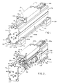
- the linear drive comprises a one piece main body 3 preferably constituted by an integral extrusion of aluminum or other similar material.
- Drive body 3 preferably has an elongate cylinder 5 therewithin receiving a cylinder sleeve 7 preferably of a material harder than main body 3.
- cylinder sleeve 7 may be of hard coated aluminum, steel or the like. It will be understood, however, that in certain linear drives of the present invention, the cylinder may be constituted by a bore in drive body 3 and a cylinder sleeve may not be necessary.
- a piston assembly as generally indicated at 9, is slidably, sealably moveable within the bore of cylinder sleeve 7 from one end thereof to the other constituting its stroke.
- a suitable pressurized fluid e.g., pressurized air
- the piston moves longitudinally within the cylinder sleeve.
- a cylinder slot as generally indicated at 11, is provided within the main body and within the cylinder sleeve 7 and extends generally lengthwise of the main body and cylinder sleeve and is in communication with the interior of the bore of the cylinder sleeve along substantially the entire length thereof.
- a carriage, as generally indicated at 13, on the exterior of the linear drive is moveable lengthwise thereof.
- Carriage 13 is reciprocally mounted on main body 3.
- the carriage is reciprocably mounted on a carriage track 15 integral with main body 3.
- carriage track 15 may not be required.
- Means, as generally indicated at 17, is coupled to piston assembly 9 and extends generally radially outwardly from the cylinder through cylinder slot 11 and is further coupled to carriage 13 for transmitting force from the piston to the carriage for effecting movement of the carriage along carriage track 15 on the exterior of main body 3 in response to movement of piston assembly 9.
- a bearing cavity 19 is provided within main body 3 and extends longitudinally of the main body in an axial direction co-linear to cylinder 5 between cylinder 5 and carriage track 15 with cylinder slot 11 extending between cylinder 5 and bearing cavity 19.
- a carriage or track slot 21 extends from bearing cavity 19 through carriage track 15 to the outer most face of the carriage track.
- piston assembly 9 is shown to comprise a piston body 23 spacing apart pistons 25a, 25b at each end thereof, each piston carrying a respective circumferential piston seal 27a, 27b for sealing its piston to the bore of cylinder sleeve 7.
- Force transmitting member 17 is attached to piston body 23 intermediate pistons 25a, 25b. The force transmitting member extends radially outwardly of cylinder sleeve 7 through cylinder slot 11.
- An elongate, cruciform-shaped bearing body, as generally indicated at 29, is secured to (or is integral with) force transmitting member 17.
- Bearing body 29 is received in bearing cavity 19 and is constrained against lateral and vertical movement relative to the bearing cavity by bearing means, as generally indicated at 31, for reacting forces into main body 3 as piston 9 and carriage 13 are moved longitudinally of the main body and as force is transferred from piston 9 to the application (not shown) coupled to carriage 13 or vice versa.
- Bearing body bearing means 31 permit longitudinal movement of the bearing body within bearing cavity 19 with minimal friction while accurately constraining the bearing body within the bearing cavity and reacting out the above-noted forces.
- bearing body 29 has an upper reach 32 which is rigidly secured to carriage 13. Upper bearing body portion 32 extends radially outwardly of the main body through carriage track slot 21 and constitutes a portion of force transmitting means 17.
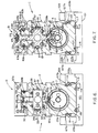
- bearing body bearing means 31 is shown to comprise a plurality of elongate strips or bars 33 of suitable low friction plastic resin bearing material, such as a non-metallic high pressure bearing material commercially available under the trade designation Murlubric from Murtfeld Plastics of Germany. These bearing bars 33 are inserted in grooves 35 on the side, top, and bottom faces of bearing body 29. Bearing bars are held longitudinally in grooves 35 by means of removable bearing member end plates 36 held in place on bearing body 29 by screws 36a (see FIGS. 3 and 6) at each end thereof.
- suitable low friction plastic resin bearing material such as a non-metallic high pressure bearing material commercially available under the trade designation Murlubric from Murtfeld Plastics of Germany.
- main body 3 carries a plurality of bearing members, as generally indicated at 37, in generally circular grooves 39 formed in the portion of main body 3 defining bearing body cavity 19. Grooves 39 are perhaps best illustrated in FIGS. 4 and 5.
- bearing body cavity bearings 37 comprise elongate steel wires inserted in grooves 39 with the diameter of the wires and the location of grooves 39 relative to bearing body cavity 19 being such that at least a portion of the bearing wires extend inwardly of the bearing cavity beyond the surfaces of main body 3 defining the bearing cavity.
- the bearing wires are in register with the elongate bearing body bearing members 33.
- low friction bearing members 33 positively engage bearing wires 37 so as to constrain the bearing body in both vertical and lateral direction, as viewed in FIGS. 6 and 7, with minimal backlash or "slop" while permitting axial movement of force transmitting member 17 and the carriage in lengthwise direction with piston assembly 9 with minimal friction.
- bearing body 29 effectively transfers force from piston assembly 9 to carriage 13, and, at the same time, is tightly constrained relative to main body 3 and reacts out reaction forces that may be applied to carriage 13 by its application (not shown). Thus, reaction forces are not transmitted to piston assembly 9 which may cause binding of the piston assembly within cylinder sleeve 7.
- low friction bearing members 33 may be shimmed relative to bearing body 29 so that the outer faces of bearing members 33 snugly engage bearing wires 37 so as to take up dimensional tolerances and to properly constrain the bearing member within bearing cavity 19.
- cylinder sleeve 7 has an elongate beveled slot 39 extending lengthwise thereof which constitutes at least a portion of cylinder slot 11.
- a dove-tail shaped pliable cylinder slot seal as generally indicated at 41, preferably, of a pliant elastomeric material, such as Nylon 6 commercially available from Bayer.
- Seal 41 has an inner part circular face 43, and beveled side faces 45a, 45b adapted to sealably mate with beveled side faces 39a, 39b of cylinder sleeve 7 defining cylinder slot 39.
- the ends of seal 41 are attached to end plates 73a, 73b (as hereinafter described) by attachment screws 42.
- main body 3 may not be necessary or desirable to provide main body 3 with a cylinder sleeve 7.
- the cylinder 5 may be constituted by a bore in the main body.
- the above-described beveled faces may be provided directly in the portions of main body 3 defining cylinder slot 11.
- cylinder slot seal 41 is longitudinally undercut along its length adjacent the apexes of beveled sleeve side faces 39a, 39b in such manner as to positively engage (i.e., to snap fit on) the ends of the beveled sleeve side faces thereby to releasably hold seal 41 in place in cylinder sleeve slot 39.
- the pressure forces act against the part circular inner face 43 of seal 41 to force the beveled side faces 45a, 45b of the seal 41 into positive sealing engagement with the corresponding beveled side faces 39a, 39b of the cylinder slot in cylinder sleeve 7.
- an alternative cylinder slot seal is shown in its entirety by reference character 41′.
- Seal 41′ has grooves 201a, 201b in its beveled side faces 45a′, 45b′ and grooves 203a, 303b in its upper face.
- the seal is preferably extruded of a suitable polyurethane or the like so as to resist wear and fatigue. However, such materials are often stiff and offer poor performance in resiliency and in affecting pressure sealing.
- elongate rod seals of a more resilient (soft) elastomeric material are inserted in respective grooves 201a, 201b on the beveled side faces 45a′, 45b′ of seal 41′ so as to sealingly engage the beveled side faces 39a, 39b of cylinder sleeve 7.
- the elongate rod seals reliably seal the slot along their entire length and thus form a line seal against beveled side faces 39a, 39b.
- Such line seals generally more reliably make a seal than face seals.
- the pressure forces acting on the inner face 43′ of seal 41′ cause the grooves 201a, 201b to sealingly grip their respective rods 205a, 205b.
- seal 41′ is undercut at the upper end of side faces 45a′, 45b′ to snap fit over the outer ends of bevel faces 39a, 39b of cylinder sleeve 7.
- Soft elongate rods 209a, 209b are inserted in top grooves 203a, 203b to permit flexing of undercuts 207a, 207b during insertion and removal of seal 41′ to and from cylinder slot 11.
- cylinder slot seal 41 is adapted to be positively drawn out of cylinder sleeve slot 39 (i.e., to "tunnel” downwardly) into the bore of cylinder sleeve 7 to extend through a tunnel 47 in force transmitting member 17 intermediate piston ends 27a, 27b and then to "tunnel upwardly” between piston ends 25a, 25b of piston assembly 9 and to remake a seal with the beveled side faces 39a, 39b of cylinder sleeve slot 39.
- the force transmitting member 17 it is possible for the force transmitting member 17 to extend radially outwardly from piston 9 through cylinder slot 39 to bearing body 29 and for the seal to be in place sealing the cylinder slot beyond piston seals 27a, 27b of piston assembly 9.
- a carriage or track slot seal 49 is removably, sealably mated with portions of main body 3 defining the carriage track 15 defining carriage slot 25 therethrough for the purpose of preventing debris, particles, and other contaminants from entering the track slot and fouling bearings 33 and 37 within bearing cavity 19.
- track slot dirt seal 49 is a pliant elongate seal made of suitable elastomeric material available from Bayer under the trade designation Durothane.
- Track seal 49 is attached at its ends to main body 3 by screws 50 and extends the entire length of the carriage slot 33.
- carriage slot 25 has opposed beveled side faces 51a, 51b at the upper ends thereof.
- Carriage slot seal 49 has corresponding beveled side faces 53a, 53b (see FIGS. 6-9) which sealingly mate with beveled side faces 51a, 51b from above, thus permitting the carriage slot seal to be sealably pressed downwardly into carriage slot 25 from above thereby to seal the carriage slot, to be unsealed from beveled faces 51a, 51b and moved upwardly away from the carriage slot so as to permit the upper portion 33 of force transmitting 37 and carriage 13 to move longitudinally of carriage slot 25, and to be re-sealed on the opposite side of the force transmitting member thereby to re-close the carriage slot intermediate the ends of carriage 13 thereby to prevent the entrance of grit, dirt, and other contaminants.
- FIGS. 6-9 As shown in FIGS.
- upper member 33 of force transmitting 17 has an upper tunnel 55 therethrough receiving seal 49 and permitting the seal to extend longitudinally through the tunnel.
- seal 49 tunnels upwardly through tunnel 55 and is lifted up from carriage slot 25 on the side of the carriage toward the direction of movement of the carriage.
- seal 49 tunnels down to remake its seal with beveled side faces 51a, 51b.
- end caps or plates 57a, 57b are provided on the outer ends of carriage 13 and are generally U-shaped so as to accommodate carriage track 15.
- a shoe-seal or wiper 59 is mounted on the bottom of end plates 57a, 57b.
- shoe-seal 59 has a resilient foam scrapper 60 at the center thereof to press down on the upper face of carriage slot seal 49 thereby to resiliently force the track slot seal into sealing engagement with beveled faces 51a, 51b of the carriage slot and further to wipe on the upper and side surfaces of carriage track 15 thereby to seal the interior of carriage body 13 relative to the side and upper faces of carriage track 15 and relative to the upper face of seal 49.
- the track slot is re-sealed thereby preventing the entrance of debris and other contaminants into track slot 21 and to protect bearings 33 and 35.
- carriage 13 comprises a unitary carriage body extrusion 61 which is rigidly secured to the upper portion 33 of force transmitting means 17 so as to insure that the carriage moves with piston assembly 9.
- carriage extrusion body 61 is an inverted channel-shaped member having a central opening adapted to fit over and to receive carriage track 15. Seal tunnel or opening 55 extends through the upper center portion of the carriage extrusion and is adapted to receive seal 49.
- the channel-shaped carriage extrusion body 61 has downwardly extending track flanges 63a, 63b. These track flanges carry low friction sliding bearing blocks or strips 65a, 65b facing inwardly toward the sides of carriage track 15. As shown best in FIGS.
- carriage track 15 has elongate grooves 67a, 67b on its outer faces thereof which receive respective wire bearing members 68a, 68b which are slidably engaged by carriage bearing blocks 65a, 65b so as to hold carriage centered with respect to carriage track 15 and to aid in constraining the carriage against lateral or rocking movement with minimal friction.
- a bearing bar 65a or 65b will engage its respective bearing wire 68a or 68b and thus transfer a substantial portion of this lateral load to main body extrusion 3. This, in turn, prevents localized application of this lateral load to only a portion of carriage track 15 thus preventing distortion of slot 21. It will be appreciated that with carriage end caps 57a, 57b securely held in place on the ends of carriage extrusion body 61, low friction bearing members 65a, 65b are held longitudinally in place with respect to the carriage body.
- a one piece cylinder plug as generally indicated at 69a, 69b, is inserted into each end of the cylinder sleeve and is sealed with respect to the bore of the cylinder sleeve by means of respective circumferential seals 71.
- the cylinder plug 69a, 69b are sealably held in place by end plates 73a, 73b which are in turn fixedly secured to the ends of main body 3 by means of suitable screws or bolts 74.
- End plates 73a, 73b also engage the ends of wire bearings 37 and 68a, 68b thus preventing longitudinal movement thereof.
- Each of the cylinder plugs 69a, 69b includes an air valve 75 which may be connected to a supply of compressed air (not shown) permitting pressurized air (or other suitable pressurized gas or low pressure liquid) to be admitted into one end of the cylinder thereby to act against the adjacent face of piston assembly 9 to effect axial movement of the piston assembly within the cylinder away from the end of the piston into which the pressurized air is admitted.
- a supply of compressed air not shown
- pressurized air or other suitable pressurized gas or low pressure liquid
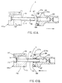
- cushioning means C comprises a tube 77 integral with its plug body 79 having an axial bore 81 extending therethrough with bore 81 being in communication with air inlet valve 75.
- a corresponding coaxial blind bore 83 is provided in the end face of piston each body 25a, 25b so as to receive tube 77 as the piston moves toward the end of its stroke (as shown in FIG. 10B).
- a relatively wide circumferential groove 85 is provided around bore 83 loosely receives an O ring assembly 87 in such manner that the O ring assembly is able to shift axially within groove 85 in a manner and for purposes as will appear.
- a port 89 is in communication with groove 85 and the end face of the piston body. It will further be noted that the outer end of tube 77 is tapered, as indicated at 90.
- FIG. 10B it will be seen as piston 25a moves toward cylinder plug 69a as the carriage moves toward the end of its stroke, bore 83 in the end face of piston body 25a coaxially receives the outer end of tube 77.
- Tube 77 has a diameter slightly larger than the inner diameter of O ring assembly 87 thereby allowing a sealing fit with the O ring assembly.
- a radial bore 91 and an intersecting longitudinal bore 93 within cylinder plug body 79 provide communication with the interior of cylinder 5.
- a metering screw 95 installed in bore 93 regulates the rate at which compressed air trapped within cylinder 5 is exhausted from air valve 75 via bores 91 and 93 thereby to trap air ahead of the advancing piston head on the non--pressurized end of the piston assembly and to release it at a controlled rate so as to pneumatically cushion the piston at the end of its stroke. More particularly, as piston 25a moving in the direction of the arrow in FIG.
- pressurized air may be admitted into bore 81 of tube 77 by air inlet valve 75 thereby to effect movement of the piston assembly 9 in the opposite direction within cylinder 5.
- This causes pressurized air to initially pressurize bore 83 of the piston body to a relatively high pressure level which initially displaces O ring assembly 87 in gland or groove 85 from the position shown in FIG. 10B generally to the opposite side of groove 85, as shown in FIG. 10A.
- pressurized air from bore 83 is then permitted to flow around tube 77 and into cylinder 5 via port 89.
- cushioning means C As air is admitted into the cylinder, it acts against the end face of piston body 25a and effects movement of the piston body within cylinder sleeve 7 in the direction of the arrow as shown in FIG. 10A. Of course, as the piston moves clear of tube 77, entering pressurized air then directly pressurizes the cylinder. It will be understood that the purpose of cushioning means C, as above-described, is to gently cushion or slow movement of the piston at the end of its stroke, but to allow startup of the piston in a rapid or breakaway manner at the start of its stroke.
- each bracket mounting base 99 comprises a base 101 extending transversely beneath the main body and having clamping or guide members 103a, 103b each side thereof extending upwardly therefrom.
- the drive body 3 has beveled shoulders 105a, 105b at the bottom thereof and clamping members 103a, 103b each have a cooperable angled flange 107a, 107b which overlies and faces its corresponding main extrusion body angled shoulders 105a or 105b, as best shown in FIGS. 4-6.
- a clamping or adjustment screw 109 draws its respective clamping members 103a, 103b forcibly downwardly relative to base 101 against its respective angled shoulder 105a, 105b.
- a low friction bearing strip 111 is carried by the angled shoulders 105a, 105b of clamp members 103a, 103b.
- bearing wire 113 is received in a groove 114 (as best shown in FIGS. 8 and 9) of main body extrusion 3.
- elongate low friction bearing strips 115 are provided in the upper face of clamp base 101 and are slidably engaged by bearing wires 117 carried in the bottom face of main body extrusion 3 in respective grooves 119, as best shown in FIGS. 8 and 9.
- Bearing wires 113 and 117 are of a relatively hard material (compared to main body extrusion 3), such as steel, stainless steel or brass.
- main body 3 may be readily reciprocated in axial direction with respect to mounting bracket 99 on low friction bearing bars 111 and 115 and bearing wires 113 and 117 while precisely held in a desired axis of movement without binding. If it is desired to fixedly clamp the fluid cylinder in a locked position with respect to its application, the low friction bearing bars 111 and 115 are replaced with suitable higher friction materials and then clamping bolts 109 are securely locked in place at any position along the length of main main body 3.
- carriage 13 may be securely mounted to a parent machine (not shown), such that actuation of the linear drive causes main body 3 to move longitudinally relative to clamp base 101 and clamps 103.
- bearing bars 111 and 115 and respective bearing wires 113 and 117 serve to permit longitudinal movement of the main body with minimal friction and to accurately constrain the main body,
- the drive unit 1 In operation of the linear drive unit 1 shown in FIGS. 1-11 of the drawings, the drive unit 1 is properly secured to its application (e.g., a robotic application) by mounting brackets 99 and with carriage 13 secured to its respective operating member of its application (also not shown).
- Pressurized fluid is admitted under pressure into one end of cylinder sleeve 7 by means of inlet valve 75 in a respective plug body 69a, 69b.
- the pressurized fluid initially acts upon bore 83 of piston body 25a so as to incipiently effect movement of piston 25a away from cylinder plug 69a.
- O ring 87 shifts within groove 85 thereby permitting pressurized fluid from bore 83 to flow through port 89 and to act against the entire end face area of piston of 25a.
- piston head 25b moves axially within the cylinder sleeve 7
- seal 41 behind piston head 25b is drawn from cylinder slot 11 and is drawn downwardly into cylinder sleeve 7 and passes through tunnel 47 in force transmitting member 17 so as to permit axial movement of force transmitting member 17 along cylinder slot 11.
- piston 9 is rigidly interconnected with carriage 13 by force transmitting member 32, the carriage is caused to move as a unit with the piston.
- bearing members 33 carried by bearing body 29 and bearing wires or rods 37 carried by main body extrusion 3 around bearing cavity 19 and bearing blocks 65a, 65b carried by carriage extrusion 61 and corresponding bearing wires 68a, 68b carried on the outer faces of the carriage slot 15 constrain and accurately guide carriage 13 and piston 9 along their respective strokes with minimal friction and without binding. In this manner, fluid pressure force may be readily transmitted from piston assembly 9 to the carriage and reaction forces of the application of the carriage (not shown) to the piston are reacted against the main extrusion body 3.
- the track slot seal 49 After the track slot seal 49 has passed through tunnel 55 of carriage extrusion 61, the track slot seal is drawn downwardly toward the track slot by means of sliding seals or cushions 59 held in place by end caps 57a 57b on the carriage so as to positively press the track slot seal 49 into the track slot and to slidingly seal against both the side and upper faces of the carriage track thereby to positively prevent dirt, debris, and other contaminants from migrating into the internal portions of the carriage 13 and to find their way into track slot 21. In this manner, the bearing members 33 and 37 are sealed against dirt and contaminants thus significantly increasing their service life.
- bearing wires 37 are preferably of steel or the like which is substantially harder than the aluminum main body extrusion, substantially all wear is born by the wire bearing members 37.
- end caps 29 on the bearing body may be removed and the low friction bearing members 31 may be replaced.
- end caps 57a, 57b on carriage 13 may be removed thus permitting replacement of the low friction strip 65a, 65b for the carriage.
- FIGS. 12-22 of the drawings show a modified form of elongate pliable slot seal that may be used either the linear drive assembly shown in FIGS. 1-11 of the drawings or in a main body modification thereof illustrated in FIGS. 15-16 of the drawings or as a single elongate pliable slot seal in a single seal cylinder drive unit shown in FIGS. 17-22 of the drawings.
- FIGS. 12-13 of the drawings the linear drive unit illustrated in FIGS. 1-11 of the drawings is shown in the cross-sectional illustration of FIG. 12, generally corresponding to FIG. 6, but with a modified form of elongate pliable slot seal for both the external seal and the internal seal, as shown in FIGS. 13-14 respectively.
- the single elongate pliable slot seal 301 used in the FIG. 12 linear drive has substantially the same configuration whether used as an external seal as shown in FIG. 13 or as an internal seal as illustrated in FIG. 14.
- the single elongate pliable slot seal 301 as shown in the external and internal slot seal applications of FIG. 13, FIG. 14, respectively, includes an extruded elastomeric body portion 303 having a shank section 305 and an enlarged head 307 at one outer end thereof.
- the enlarged head 307 preferably has the cross-sectional configuration illustrated where it first tapers away from the shank section 305, then extends in an axial direction for a short distance and finally assumes a curvilinear shape to meet the transversely extending outer face.
- the seal 301 further includes, at an opposite end of the shank section 305, a flexible sealing wiper 309, preferably a stainless steel sealing strip which is secured by an adhesive or other suitable method to the outer free end of the shank section 305.
- a flexible sealing wiper 309 preferably a stainless steel sealing strip which is secured by an adhesive or other suitable method to the outer free end of the shank section 305.
- Opposite marginal edge portions 311, 311 of the flexible sealing wiper sealable engage spaced surfaces adjacent the external or internal slot, as will become apparent.
- the elongate pliable slot seal 301 sealably disengages and engages spaced surfaces adjacent the external or carriage slot 25 in the main body 3.
- the enlarged head 307 engages the internal shoulders 313, 313 at the lower end of the beveled side faces 51A, 51B which taper downwardly and inwardly to the spaced internal shoulders 313, 313, on opposite sides of the external or carriage slot 25.
- Enlarged head 307 of the elastomeric body portion 303 of the seal 301 compressibly engages the internal shoulders 313, 313 so as to allow the enlarged head 307 to move below the internal shoulder 313, 313 for releasably holding the seal 301 in position relative to the external slot 25.
- the elastomeric enlarged head 307 has a width greater than the distance between the internal shoulders 313, 313, causing the enlarged head 307 to deform as it passes by the internal shoulders 313, 313 until it assumes a position generally illustrated in FIG. 13 of the drawings where the enlarged head 307 releasably holds the seal 301 in position relative to the external slot 25.
- the flexible sealing wiper 309 which extends laterally outwardly beyond the shank section 305 of the elastomeric body portion 303 and the enlarged head 307, is in position to sealably engage the downwardly and inwardly tapering bevel side faces 51A, 51B adjacent the external slot 25.
- the opposite marginal edge portions 311, 311 slidably and sealably engage the spaced downwardly and inwardly tapering bevel side faces 51A, 51B adjacent the external slot 25, throughout pressure differential changes in the linear drive assembly.
- the seal 301 for use in sealing the internal slot 11, is illustrated in FIG. 14 as operating in generally the same way as in the FIG. 13 external slot application, with the following differences.
- the seal 301 is reversly positioned from the FIG. 13 external slot application.
- the enlarged head 307 engages internal shoulders 315, 315 adjacent the internal slot 11, while the marginal edge portions 311, 311 of the flexible sealing wiper 309 are positioned to engage the spaced curvilinear or cylindrical surfaces 317, 317 on opposite sides of the internal or cylindrical slot 11.
- opposite marginal edge portions 311, 311 in the seal 301 are illustrated in FIG. 14 as including tapered edges, as distinct from those shown in FIG. 13, in order to facilitate sealing of the spaced curvilinear or cylindrical surfaces 317, 317.
- the tapered edges are an optional variation which are useful in certain applications.
- the shank section 305 of the seal 301 is laterally spaced from the spaced surfaces adjacent the slot in each case to enable the opposite marginal edge portions 311, 311 of the flexible sealing wiper 309 to firmly and sealably engage the spaced surfaces adjacent the slot, without pressure differential build up behind the flexible sealing wiper 309.
- no pressure can be trapped behind the stainless steel flexible sealing wiper 309 since no pressure can be accumulated between the flexible sealing wiper 309 and the shank section 305 of the elastomeric body portion 303. This will assure a firmer contact between the flexible sealing wiper 309 and the spaced surfaces adjacent the external or internal slot in the FIGS. 13-14 illustrations.
- the seal 301 may be used in a modified construction of the main body 3′ illustrated in FIGS. 15-16 of the drawings.
- the surfaces surrounding the external slot 25, have a different construction, as best illustrated in FIG. 16 of the drawings.
- the downwardly and inwardly tapering surfaces 319, 319 are substantially shorter in height than the side faces 51A, 51B shown in FIG. 13 of the drawings.
- the internal shoulders 313, 313 are provided for engaging the enlarged head 307, in the same manner as described in connection with FIG. 13.
- a complementary configured recess 321, 321 may be provided (see FIG. 16) on opposite sides of the external slot 25 for receiving marginal edge portions 311, 311 of the flexible sealing wiper 309 therein.
- This provides a smooth and continuous upper surface and an enhanced dirt seal.
- the flexible sealing wiper 309 may simply rest upon the upper outer surface of the main body extrusion 3, as illustrated.
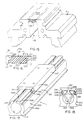
- FIGS. 17-22 of the drawings illustrate a modified form of linear drive assembly 1′ for use in single seal applications.
- the one-piece main body 330 has an elongate outer body cylindrical configuration 331 and an elongate cylinder bore 333 formed therein.
- the one-piece main body 330 is preferably formed as an integral extrusion of aluminum or other similar material, with a supporting pedestal or foot 335, as best illustrated in FIGS. 17-18.
- a carriage 337 is movable along the cylinder body 330 exteriorly thereof.
- outer cylinder body 330 on opposite upper sides thereof at 339, 339 and the downwardly extending track flanges 341, 341 at 343, 343 have semi-circular openings for receiving solid or composite bearing members 345, 345 carried by the carriage 337 thus enables slidable movement of the carriage 337 relative to the cylinder body 330, along the outer corresponding semi-circular openings 339, 339 thereof.
- means generally indicated at 347 is coupled to a piston assembly (not shown) and extends radially outwardly from the cylinder 333 through cylinder slot 349, for further coupling to the carriage 337, in order to transmit force from the piston (not shown) to the carriage 337 for effecting movement of the carriage 337 along the bearing members 345, 345 on the exterior of the body cylinder 330, in response to movement of the piston assembly (not shown).
- the general operation of the aforementioned components is the same as in the FIGS. 1-11 embodiment, differing principally in the modified shape and configuration of the various components, as illustrated.
- the modified linear drive assembly 1′ has a much smaller height and width, enabling the linear drive assembly 1 to be used in application environments where size and space are limiting factors.
- FIGS. 19-22 of the drawings shows the single elongate pliable slot seal 301 used in conjunction with the main cylinder body 330 of the modified linear drive assembly 1′.
- a single cylinder slot seal 349 which comprises both the internal and external slot seal in the modified linear drive assembly 1′.
- the single elongate pliable slot seal 301 operates much in the same manner as described in connection with the internal slot seal 301 in the FIG. 14 illustration.
- the enlarged head 307 of the elastomeric body portion 303 releasably engages the spaced internal shoulders 315, 315 in the cylindrical slot 349, while the opposite marginal edge portions 311, 311 of the flexible sealing wiper 309 slidably and sealably engage the spaced curvilinear or cylindrical surfaces 317, 317 on opposite sides of the cylindrical slot 349.
- the single elongate pliable slot seal 301 as shown in FIG. 20 may be used as both an external dirt seal and an internal pressure seal, as will be apparent.
- FIGS. 21-22 shows a modified single elongate pliable slot seal construction in order to achieve the improved releasable holding of the seal 301, while achieving an enhanced internal dirt seal.
- the enlarged head 307 has a modified shape for reception within complementary shaped outer recess surfaces 351, 351, as illustrated.
- the modified generally polygonally shaped enlarged head 307 fits within corresponding complementary shaped outer recess surfaces 351, 351, such that a smooth upper profile including the seal 301 and outer cylindrical body 330, offers an easy to clean outer surface area.
- the complementary mating engagement between the generally polygonally shaped enlarged head 307 and the complementary shaped outer recess surfaces 351, 351 causes the seal 301 to be secure but releasably latched or held in place against inward pressure differential.
- the upper outer face of the elastomeric body portion 303 may have a flat surface 353 as shown in FIG. 20, or may be indented at 355 as shown in FIG. 22 to enhance the flexibility, and therefore the releasable locking action of the generally polygonally shaped enlarged head 307 for secure complementary mating engagement with the complementary shaped outer recess surfaces 351, 351.
- the single elongate pliable seal 301 enables the upper part of the carriage 337 to be much simpler, as well as lower in height, since it does not need to have a mechanism and channel to lift an upper seal out of and back into its corresponding slot at every passing, as would be the case of the drive assembly 1 shown in FIGS. 1-11 of the drawings.
- the modified drive assembly 1′, together with the single elongated pliable slot seal 301, provides a much simpler, smaller in dimension linear drive assembly where space and size in the desired application are limiting factors, as noted.
Landscapes
- Engineering & Computer Science (AREA)
- Physics & Mathematics (AREA)
- Fluid Mechanics (AREA)
- Mechanical Engineering (AREA)
- General Engineering & Computer Science (AREA)
- Actuator (AREA)
- Sealing With Elastic Sealing Lips (AREA)
- Sealing Devices (AREA)
Applications Claiming Priority (4)
| Application Number | Priority Date | Filing Date | Title |
|---|---|---|---|
| US785498 | 1985-10-08 | ||
| US66434891A | 1991-03-04 | 1991-03-04 | |
| US78549891A | 1991-10-31 | 1991-10-31 | |
| US664348 | 1991-10-31 |
Publications (1)
| Publication Number | Publication Date |
|---|---|
| EP0502810A1 true EP0502810A1 (fr) | 1992-09-09 |
Family
ID=27098948
Family Applications (1)
| Application Number | Title | Priority Date | Filing Date |
|---|---|---|---|
| EP92630023A Withdrawn EP0502810A1 (fr) | 1991-03-04 | 1992-03-04 | Moteur linéaire avec vérin à piston sans tige |
Country Status (3)
| Country | Link |
|---|---|
| EP (1) | EP0502810A1 (fr) |
| JP (1) | JPH0674209A (fr) |
| IE (1) | IE920673A1 (fr) |
Cited By (4)
| Publication number | Priority date | Publication date | Assignee | Title |
|---|---|---|---|---|
| EP0723083A3 (fr) * | 1995-01-20 | 1997-06-25 | Imi Norgren Gmbh | Vérin à fluide sous pression |
| EP0781931A1 (fr) * | 1995-12-27 | 1997-07-02 | Howa Machinery, Ltd. | Dispositif d'entraînement linéaire |
| EP0724082A3 (fr) * | 1991-10-11 | 1998-03-11 | Smc Kabushiki Kaisha | Vérin sans tige |
| EP1573189A4 (fr) * | 2002-11-15 | 2008-09-03 | Phd Inc | Ensemble coulisse sans tige |
Families Citing this family (1)
| Publication number | Priority date | Publication date | Assignee | Title |
|---|---|---|---|---|
| JP7366386B2 (ja) | 2018-08-02 | 2023-10-23 | 株式会社コスメック | ワーク挙動検出機能を備えたクランプシステム |
Citations (7)
| Publication number | Priority date | Publication date | Assignee | Title |
|---|---|---|---|---|
| EP0033541A1 (fr) * | 1980-01-31 | 1981-08-12 | Tol-O-Matic, Inc. | Vérin à pression de fluide |
| DE3124878C1 (de) * | 1981-06-25 | 1982-12-09 | Kaiser, Siegmund H., Ing.(grad.), 7440 Nürtingen | Druckmittelzylinder |
| EP0082829A1 (fr) * | 1981-12-22 | 1983-06-29 | AB Mecman | Dispositif associé à un cylindre à pression de fluide sans tige de piston |
| EP0104364A1 (fr) * | 1982-08-05 | 1984-04-04 | Knorr-Bremse Ag | Vérin sans tige de piston avec frein |
| US4545290A (en) * | 1983-12-23 | 1985-10-08 | Tol-O-Matic, Inc. | Pressure cylinder |
| DE3802703A1 (de) * | 1987-01-30 | 1988-08-11 | Howa Machinery Ltd | Kolbenstangenlose zylinderanordnung |
| GB2202587A (en) * | 1987-03-12 | 1988-09-28 | Ckd Corp | Rod-less piston and cylinder assembly |
-
1992
- 1992-03-03 IE IE920673A patent/IE920673A1/en not_active Application Discontinuation
- 1992-03-04 EP EP92630023A patent/EP0502810A1/fr not_active Withdrawn
- 1992-03-04 JP JP4082842A patent/JPH0674209A/ja active Pending
Patent Citations (8)
| Publication number | Priority date | Publication date | Assignee | Title |
|---|---|---|---|---|
| EP0033541A1 (fr) * | 1980-01-31 | 1981-08-12 | Tol-O-Matic, Inc. | Vérin à pression de fluide |
| DE3124878C1 (de) * | 1981-06-25 | 1982-12-09 | Kaiser, Siegmund H., Ing.(grad.), 7440 Nürtingen | Druckmittelzylinder |
| EP0082829A1 (fr) * | 1981-12-22 | 1983-06-29 | AB Mecman | Dispositif associé à un cylindre à pression de fluide sans tige de piston |
| EP0104364A1 (fr) * | 1982-08-05 | 1984-04-04 | Knorr-Bremse Ag | Vérin sans tige de piston avec frein |
| US4545290A (en) * | 1983-12-23 | 1985-10-08 | Tol-O-Matic, Inc. | Pressure cylinder |
| US4545290B1 (fr) * | 1983-12-23 | 1993-03-30 | Tol O Matic Inc | |
| DE3802703A1 (de) * | 1987-01-30 | 1988-08-11 | Howa Machinery Ltd | Kolbenstangenlose zylinderanordnung |
| GB2202587A (en) * | 1987-03-12 | 1988-09-28 | Ckd Corp | Rod-less piston and cylinder assembly |
Cited By (6)
| Publication number | Priority date | Publication date | Assignee | Title |
|---|---|---|---|---|
| EP0724082A3 (fr) * | 1991-10-11 | 1998-03-11 | Smc Kabushiki Kaisha | Vérin sans tige |
| EP0723083A3 (fr) * | 1995-01-20 | 1997-06-25 | Imi Norgren Gmbh | Vérin à fluide sous pression |
| US5692428A (en) * | 1995-01-20 | 1997-12-02 | Imi Norgren Gmbh | Fluid-powered cylinder |
| EP0781931A1 (fr) * | 1995-12-27 | 1997-07-02 | Howa Machinery, Ltd. | Dispositif d'entraînement linéaire |
| US5701798A (en) * | 1995-12-27 | 1997-12-30 | Howa Machinery, Ltd. | Linear actuating device |
| EP1573189A4 (fr) * | 2002-11-15 | 2008-09-03 | Phd Inc | Ensemble coulisse sans tige |
Also Published As
| Publication number | Publication date |
|---|---|
| IE920673A1 (en) | 1992-09-09 |
| JPH0674209A (ja) | 1994-03-15 |
Similar Documents
| Publication | Publication Date | Title |
|---|---|---|
| FI74783C (fi) | Anordning vid en kolvstaongsloes tryckmediecylinder. | |
| US4724744A (en) | Carrier bracket for power cylinder | |
| EP0147803B1 (fr) | Cylindre à pression | |
| KR100658471B1 (ko) | 공구의 공압식 조작 장치 | |
| US4852465A (en) | Carrier bracket for power cylinder | |
| US4067584A (en) | Guiding and sealing arrangements for pistons, piston rods and the like | |
| EP0033541A1 (fr) | Vérin à pression de fluide | |
| US5333535A (en) | Rodless cylinder | |
| JPH0765602B2 (ja) | ロツドレスシリンダ | |
| EP0502810A1 (fr) | Moteur linéaire avec vérin à piston sans tige | |
| ATE159198T1 (de) | Pneumatische steuervorrichtung für heisskanalnadelventile für spritzgiesswerkzeuge | |
| WO1991004814A1 (fr) | Dispositif de fixation reglable | |
| US4204948A (en) | Self-purging seal | |
| US4838147A (en) | Pressure fluid actuator | |
| EP0402413B1 (fr) | Racleur de bande de manutention | |
| CA2062187A1 (fr) | Dispositif d'entrainement lineaire | |
| JPS5846242Y2 (ja) | 線形作動器 | |
| US5988042A (en) | Rodless cylinder with internal bearings | |
| AU602499B2 (en) | A joint system | |
| US4380951A (en) | Mud pump piston assembly | |
| SG44482A1 (en) | Improved seal | |
| CN214692702U (zh) | 一种机械膨胀轴 | |
| CN219229964U (zh) | 一种活检钳用耐磨压条 | |
| US6257123B1 (en) | Rodless slides | |
| GB2161852A (en) | Seal |
Legal Events
| Date | Code | Title | Description |
|---|---|---|---|
| PUAI | Public reference made under article 153(3) epc to a published international application that has entered the european phase |
Free format text: ORIGINAL CODE: 0009012 |
|
| AK | Designated contracting states |
Kind code of ref document: A1 Designated state(s): AT BE CH DE DK ES FR GB GR IT LI LU NL PT SE |
|
| 18D | Application deemed to be withdrawn |
Effective date: 19930310 |