EP0402603A1 - Dispositif antiglissement pour véhicules en état stationnaire - Google Patents
Dispositif antiglissement pour véhicules en état stationnaire Download PDFInfo
- Publication number
- EP0402603A1 EP0402603A1 EP90108365A EP90108365A EP0402603A1 EP 0402603 A1 EP0402603 A1 EP 0402603A1 EP 90108365 A EP90108365 A EP 90108365A EP 90108365 A EP90108365 A EP 90108365A EP 0402603 A1 EP0402603 A1 EP 0402603A1
- Authority
- EP
- European Patent Office
- Prior art keywords
- housing
- car
- brake pedal
- wheels
- retainer plate
- Prior art date
- Legal status (The legal status is an assumption and is not a legal conclusion. Google has not performed a legal analysis and makes no representation as to the accuracy of the status listed.)
- Withdrawn
Links
Images

Classifications
-
- B—PERFORMING OPERATIONS; TRANSPORTING
- B60—VEHICLES IN GENERAL
- B60W—CONJOINT CONTROL OF VEHICLE SUB-UNITS OF DIFFERENT TYPE OR DIFFERENT FUNCTION; CONTROL SYSTEMS SPECIALLY ADAPTED FOR HYBRID VEHICLES; ROAD VEHICLE DRIVE CONTROL SYSTEMS FOR PURPOSES NOT RELATED TO THE CONTROL OF A PARTICULAR SUB-UNIT
- B60W10/00—Conjoint control of vehicle sub-units of different type or different function
- B60W10/04—Conjoint control of vehicle sub-units of different type or different function including control of propulsion units
- B60W10/06—Conjoint control of vehicle sub-units of different type or different function including control of propulsion units including control of combustion engines
-
- B—PERFORMING OPERATIONS; TRANSPORTING
- B60—VEHICLES IN GENERAL
- B60T—VEHICLE BRAKE CONTROL SYSTEMS OR PARTS THEREOF; BRAKE CONTROL SYSTEMS OR PARTS THEREOF, IN GENERAL; ARRANGEMENT OF BRAKING ELEMENTS ON VEHICLES IN GENERAL; PORTABLE DEVICES FOR PREVENTING UNWANTED MOVEMENT OF VEHICLES; VEHICLE MODIFICATIONS TO FACILITATE COOLING OF BRAKES
- B60T11/00—Transmitting braking action from initiating means to ultimate brake actuator without power assistance or drive or where such assistance or drive is irrelevant
- B60T11/10—Transmitting braking action from initiating means to ultimate brake actuator without power assistance or drive or where such assistance or drive is irrelevant transmitting by fluid means, e.g. hydraulic
- B60T11/103—Transmitting braking action from initiating means to ultimate brake actuator without power assistance or drive or where such assistance or drive is irrelevant transmitting by fluid means, e.g. hydraulic in combination with other control devices
- B60T11/105—Transmitting braking action from initiating means to ultimate brake actuator without power assistance or drive or where such assistance or drive is irrelevant transmitting by fluid means, e.g. hydraulic in combination with other control devices with brake locking after actuation, release of the brake by a different control device, e.g. gear lever
-
- B—PERFORMING OPERATIONS; TRANSPORTING
- B60—VEHICLES IN GENERAL
- B60T—VEHICLE BRAKE CONTROL SYSTEMS OR PARTS THEREOF; BRAKE CONTROL SYSTEMS OR PARTS THEREOF, IN GENERAL; ARRANGEMENT OF BRAKING ELEMENTS ON VEHICLES IN GENERAL; PORTABLE DEVICES FOR PREVENTING UNWANTED MOVEMENT OF VEHICLES; VEHICLE MODIFICATIONS TO FACILITATE COOLING OF BRAKES
- B60T7/00—Brake-action initiating means
- B60T7/12—Brake-action initiating means for automatic initiation; for initiation not subject to will of driver or passenger
- B60T7/122—Brake-action initiating means for automatic initiation; for initiation not subject to will of driver or passenger for locking of reverse movement
-
- B—PERFORMING OPERATIONS; TRANSPORTING
- B60—VEHICLES IN GENERAL
- B60W—CONJOINT CONTROL OF VEHICLE SUB-UNITS OF DIFFERENT TYPE OR DIFFERENT FUNCTION; CONTROL SYSTEMS SPECIALLY ADAPTED FOR HYBRID VEHICLES; ROAD VEHICLE DRIVE CONTROL SYSTEMS FOR PURPOSES NOT RELATED TO THE CONTROL OF A PARTICULAR SUB-UNIT
- B60W10/00—Conjoint control of vehicle sub-units of different type or different function
- B60W10/04—Conjoint control of vehicle sub-units of different type or different function including control of propulsion units
-
- B—PERFORMING OPERATIONS; TRANSPORTING
- B60—VEHICLES IN GENERAL
- B60W—CONJOINT CONTROL OF VEHICLE SUB-UNITS OF DIFFERENT TYPE OR DIFFERENT FUNCTION; CONTROL SYSTEMS SPECIALLY ADAPTED FOR HYBRID VEHICLES; ROAD VEHICLE DRIVE CONTROL SYSTEMS FOR PURPOSES NOT RELATED TO THE CONTROL OF A PARTICULAR SUB-UNIT
- B60W10/00—Conjoint control of vehicle sub-units of different type or different function
- B60W10/18—Conjoint control of vehicle sub-units of different type or different function including control of braking systems
-
- G—PHYSICS
- G05—CONTROLLING; REGULATING
- G05G—CONTROL DEVICES OR SYSTEMS INSOFAR AS CHARACTERISED BY MECHANICAL FEATURES ONLY
- G05G1/00—Controlling members, e.g. knobs or handles; Assemblies or arrangements thereof; Indicating position of controlling members
- G05G1/30—Controlling members actuated by foot
- G05G1/46—Means, e.g. links, for connecting the pedal to the controlled unit
-
- Y—GENERAL TAGGING OF NEW TECHNOLOGICAL DEVELOPMENTS; GENERAL TAGGING OF CROSS-SECTIONAL TECHNOLOGIES SPANNING OVER SEVERAL SECTIONS OF THE IPC; TECHNICAL SUBJECTS COVERED BY FORMER USPC CROSS-REFERENCE ART COLLECTIONS [XRACs] AND DIGESTS
- Y10—TECHNICAL SUBJECTS COVERED BY FORMER USPC
- Y10T—TECHNICAL SUBJECTS COVERED BY FORMER US CLASSIFICATION
- Y10T74/00—Machine element or mechanism
- Y10T74/20—Control lever and linkage systems
- Y10T74/20528—Foot operated
-
- Y—GENERAL TAGGING OF NEW TECHNOLOGICAL DEVELOPMENTS; GENERAL TAGGING OF CROSS-SECTIONAL TECHNOLOGIES SPANNING OVER SEVERAL SECTIONS OF THE IPC; TECHNICAL SUBJECTS COVERED BY FORMER USPC CROSS-REFERENCE ART COLLECTIONS [XRACs] AND DIGESTS
- Y10—TECHNICAL SUBJECTS COVERED BY FORMER USPC
- Y10T—TECHNICAL SUBJECTS COVERED BY FORMER US CLASSIFICATION
- Y10T74/00—Machine element or mechanism
- Y10T74/20—Control lever and linkage systems
- Y10T74/20576—Elements
- Y10T74/20888—Pedals
Definitions
- the present invention relates generally to an antislipping device for cars in a stationary state. especially to a device able to hold the brakes of cars in a stationary state so as to prevent them from moving when stationed on inclined ground.
- a car driver should pull up or press down the emergency brake of the car so as to avoid the car from slipping when stationed on an inclined ground.
- a car driver may forget to pull up or press down the emergency brake when the car is parked.
- the car will begin to slip down and an accident will inevitably occur.
- the car is halted on a sloping road and the driver forgets to keep on treading the brake pedal or forgets to pull up the emergency brake, then the car will begin to slip down and collide with the car halted behind or ahead.
- the primary object of the present invention is to provide an antislipping device for cars in a stationary state, which is able to hold the brake of a car when the brake pedal has been trodden down to stop the moving of the car.
- an antislipping device for cars in a stationary state which includes: means for detecting the rotation of the car wheels and constantly outputing signal which indicates if the wheels of the car are in a state of rotation or not; means for preventing the brake pedal of the car from moving backward and holding on the brake pedal when the brake pedal is trodden down to stop the moving of the car; and control means electrically connected with the detect means and the prevent means, for receiving the output signal from the detect means and conducting the prevent means to release the brake pedal when the car wheels are kept still and the accelerator pedal of the car is trodden down to exceed a predetermined extent.
- the antislipping device for cars in a stationary state comprises a CPU 10, a tachometer 11, an electromagnetic latch 12 and a sensor 15.
- the tachometer 11 can be of any form as long as it can detect the rotation of the car wheels.
- the tachometer 11 can be a conventional one mounted near one of the car wheels.
- the sensor 15 is mounted near the accelerator pedal (not shown) of the car.
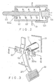
- the electromagnetic latch 12 is mounted near a retainer plate 201a of the link 201 of the brake pedal 20 of the car.
- the CPU 10 is accommodated within a suitable space in the car.
- the retainer plate 201a is integrally formed with the link 201 of the brake pedal 20.
- the retainer plate 201a has a plurality of holes 23.
- the sectional views of the holes 23 are shown in Fig. 6.
- each hole 23 has a slop side wall 23b so that the retainer plate 201a is able to move (relative to the slide bolt 122) in the direction of the arrow B without any impedance, and is prevented from moving in the reversed direction.
- the tachometer 11, the electromagnetic latch 12 and the sensor 15 are electrically connected with the CPU 10 by way of an input port 13 and an output port 14.
- the tachometer 11 is so designed that it constantly outputs a signal to the CPU 10 which indicates whether the wheels of the car are rotating or not.
- the sensor 15 is designed to output a signal to the CPU 10 when it senses the accelerator pedal (not shown) of the car is trodden down to a certain extent.
- the construction of the electromagnetic latch 12 shown in Fig. 2 comprises a cylindrical housing 121, a slide bolt 122, a cap 123, an electromagnet 124 and a coil spring 125.
- the slide bolt 122 is slidably mounted within the housing 121 which is threadedly engaged with the cap 123.
- the coil spring 125 is accommodated between the flange 122a of the slide bolt 122 and the cap 123, so as to urge the slide bolt 122 away from the electromagnet 124.
- the electromagnet 124 is secured on the cap 123. When the electromagnet 124 is activated, the slide bolt 122 will be attracted toward the electromagnet 124, that is, the slide bolt 122 will retreat to some extent into the housing 121.
- Fig. 3 is an enlarged perspective view showing how the electromagnetic latch 12 holds the brake pedal 20.
- the slide bolt 122 of the electromagnetic latch 12 penetrates one of the holes 23 of the retainer plate 201a of the brake pedal 20 which has been trodden down (in the direction of the arrow B). In this case, the brake pedal 20 is restrained to be released, that is, the brake pedal 20 is held. If the slide bolt 122 retreats to a certain extent so that it no more hinders the backward motion of the brake pedal 20, then the brake pedal 20 will disengage with the slide bolt 122 and move back to its original position, that is, the brake pedal 20 will be released from being trapped.
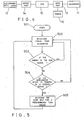
- the CPU 10 of the anti slipping device As shown in Fig. 5, when the ignition switch (not shown) of the car is turned on, the CPU 10 is activated (step 501) and starts to receive signal from the tachometer 11 (step 502), then, the CPU 10 checks the signal coming from the tachometer 11 (step 503). If the signal coming from the tachometer indicates that the wheels of the car are in a state of rotation, then the process goes back to step 502, that is, keeps on receiving signal from the tachometer 11.
- step 504 the CPU checks the sensor 15 (step 504), if the signal coming from the sensor 15 shows that the accelerator pedal is trodden down to a certain extent (described hereinafter), then the CPU conducts the electromagnetic latch 12 to withdraw the slide bolt 122 for a predetermined time period (step 505). After this, the process goes back to step 502 and keeps on running. If the ignition switch is turned off, then the CPU 10 stops working.
- the R.P.M. of the engine will rise.
- the R.P.M. of the engine reaches a predetermined value, that is, the accelerator pedal is trodden down to a certain extent, the slide bolt 122 of the eletromagnetic latch 12 will be withdrawn and let the brake pedal spring back to its original location, that is, release the brake.
- the driver may release the clutch pedal to drive the car.
- the slide bolt will retreat automatically when the R.P.M. of the engine reaches a predetermined value, thus avoiding trapping the car.
Landscapes
- Engineering & Computer Science (AREA)
- Chemical & Material Sciences (AREA)
- Combustion & Propulsion (AREA)
- Transportation (AREA)
- Mechanical Engineering (AREA)
- Physics & Mathematics (AREA)
- General Physics & Mathematics (AREA)
- Automation & Control Theory (AREA)
- Braking Elements And Transmission Devices (AREA)
- Regulating Braking Force (AREA)
Applications Claiming Priority (1)
| Application Number | Priority Date | Filing Date | Title |
|---|---|---|---|
| US07/364,098 US4942949A (en) | 1989-06-12 | 1989-06-12 | Antislipping device for cars in a stationary state |
Publications (1)
| Publication Number | Publication Date |
|---|---|
| EP0402603A1 true EP0402603A1 (fr) | 1990-12-19 |
Family
ID=23433003
Family Applications (1)
| Application Number | Title | Priority Date | Filing Date |
|---|---|---|---|
| EP90108365A Withdrawn EP0402603A1 (fr) | 1989-06-12 | 1990-05-03 | Dispositif antiglissement pour véhicules en état stationnaire |
Country Status (2)
| Country | Link |
|---|---|
| US (1) | US4942949A (fr) |
| EP (1) | EP0402603A1 (fr) |
Cited By (2)
| Publication number | Priority date | Publication date | Assignee | Title |
|---|---|---|---|---|
| EP0536014A1 (fr) * | 1991-09-30 | 1993-04-07 | AlliedSignal Freni S.p.A. | Maître-cylindre verrouillable |
| EP0653694A1 (fr) * | 1993-11-12 | 1995-05-17 | Young-Ryeol Song | Pédales pour automobiles |
Families Citing this family (13)
| Publication number | Priority date | Publication date | Assignee | Title |
|---|---|---|---|---|
| US5078456A (en) * | 1990-03-30 | 1992-01-07 | Cox Terry L | Brake pedal retaining vehicular anti-theft brake locking mechanism |
| US5233882A (en) * | 1990-07-12 | 1993-08-10 | General Motors Corporation | Remote control lever module |
| US5458021A (en) * | 1993-12-02 | 1995-10-17 | New Holland North America, Inc. | Control lever neutral lock mechanism |
| US5842384A (en) * | 1995-03-01 | 1998-12-01 | Safety Systems & Controls, Inc. | Shift inhibitor |
| JP3189043B2 (ja) * | 1996-09-18 | 2001-07-16 | 現代自動車株式会社 | ブレーキペダル固定装置 |
| SE518099C2 (sv) | 1997-11-21 | 2002-08-27 | Claes Johansson Automotive Ab | Inställbart pedalställ för ett fordon |
| ES2184429T3 (es) * | 1998-03-26 | 2003-04-01 | Meritor Automotive Inc | Sistema de freno de estacionamiento para vehiculos equipados con frenos electronicos. |
| US6615624B2 (en) * | 1999-01-25 | 2003-09-09 | Douglas C. Cardwell | Motor vehicle anti-theft apparatus and method |
| US6393934B1 (en) | 2000-06-21 | 2002-05-28 | Teleflex Incorporated | Break-away pedal with ball swivel snap-in |
| US6612200B1 (en) | 2000-06-23 | 2003-09-02 | Teleflex Incorporated | Pop out brake pedal |
| NO320251B1 (no) * | 2002-12-23 | 2005-11-14 | Per Espen Vik | Anordning ved parkerings-bremsesystem for kjoretoy |
| KR100789438B1 (ko) * | 2006-11-14 | 2007-12-28 | 울산대학교 산학협력단 | 자동차의 브레이크 페달 커버 및 브레이크 페달 조립체 |
| US20090158790A1 (en) * | 2007-12-21 | 2009-06-25 | Oliver Richard D | Vehicle Immobilization System |
Citations (5)
| Publication number | Priority date | Publication date | Assignee | Title |
|---|---|---|---|---|
| FR2419846A1 (fr) * | 1978-03-15 | 1979-10-12 | Garces Guy | Antivol pour vehicules automobiles |
| DE3426669A1 (de) * | 1984-07-25 | 1986-01-23 | Kia Industrial Co., Ltd., Seoul | Automatisches bremsregelsystem |
| EP0221299A2 (fr) * | 1985-09-30 | 1987-05-13 | AlliedSignal Inc. | Dispositif de relâchement pour frein d'arrêt |
| DE3642874A1 (de) * | 1986-12-16 | 1988-06-30 | Daimler Benz Ag | Einrichtung fuer eine parkbremse an einem kraftfahrzeug |
| GB2210344A (en) * | 1987-10-01 | 1989-06-07 | Eric Jeffrey Edmunds | Anti-theft lock acting on vehicle brakes |
Family Cites Families (7)
| Publication number | Priority date | Publication date | Assignee | Title |
|---|---|---|---|---|
| US2816633A (en) * | 1954-06-29 | 1957-12-17 | N A Saigh | Automatic parking brake |
| US3229792A (en) * | 1962-11-29 | 1966-01-18 | Harley Davidson Motor Co Inc | Vehicle control system |
| US3482666A (en) * | 1967-11-08 | 1969-12-09 | Walter Case | Brake setting device |
| US3513953A (en) * | 1968-06-20 | 1970-05-26 | Stevens Appliance Truck Co | Brake and motor control for electric vehicle |
| US4076093A (en) * | 1976-03-31 | 1978-02-28 | Goshi Kaisha Mizuno Kogeisha | Braking control apparatus for a vehicle |
| US4310064A (en) * | 1979-02-01 | 1982-01-12 | Kazarian Jr Adam | Multi-purpose automobile brake anti-creep device |
| US4696222A (en) * | 1985-08-08 | 1987-09-29 | Han Joon H | Brake holding system |
-
1989
- 1989-06-12 US US07/364,098 patent/US4942949A/en not_active Expired - Fee Related
-
1990
- 1990-05-03 EP EP90108365A patent/EP0402603A1/fr not_active Withdrawn
Patent Citations (5)
| Publication number | Priority date | Publication date | Assignee | Title |
|---|---|---|---|---|
| FR2419846A1 (fr) * | 1978-03-15 | 1979-10-12 | Garces Guy | Antivol pour vehicules automobiles |
| DE3426669A1 (de) * | 1984-07-25 | 1986-01-23 | Kia Industrial Co., Ltd., Seoul | Automatisches bremsregelsystem |
| EP0221299A2 (fr) * | 1985-09-30 | 1987-05-13 | AlliedSignal Inc. | Dispositif de relâchement pour frein d'arrêt |
| DE3642874A1 (de) * | 1986-12-16 | 1988-06-30 | Daimler Benz Ag | Einrichtung fuer eine parkbremse an einem kraftfahrzeug |
| GB2210344A (en) * | 1987-10-01 | 1989-06-07 | Eric Jeffrey Edmunds | Anti-theft lock acting on vehicle brakes |
Cited By (2)
| Publication number | Priority date | Publication date | Assignee | Title |
|---|---|---|---|---|
| EP0536014A1 (fr) * | 1991-09-30 | 1993-04-07 | AlliedSignal Freni S.p.A. | Maître-cylindre verrouillable |
| EP0653694A1 (fr) * | 1993-11-12 | 1995-05-17 | Young-Ryeol Song | Pédales pour automobiles |
Also Published As
| Publication number | Publication date |
|---|---|
| US4942949A (en) | 1990-07-24 |
Similar Documents
| Publication | Publication Date | Title |
|---|---|---|
| US4942949A (en) | Antislipping device for cars in a stationary state | |
| US20050246081A1 (en) | Method and system to prevent unintended rolling of a vehicle | |
| US20210269001A1 (en) | Electric brake apparatus, electric brake control apparatus, and brake control apparatus | |
| JPH11235969A (ja) | 車両ブレーキ装置の制御方法及び装置 | |
| EP0363634A1 (fr) | Dispositif de freinage d'un véhicule à moteur utilisant la pédale d'accélérateur | |
| US3610362A (en) | Antiskid device with clutch releasing means | |
| US6296327B1 (en) | Braking device | |
| US7375438B2 (en) | Method and device for controlling a roll-back prevention system | |
| US3433336A (en) | Throttle operated brake holder | |
| WO2008115132A1 (fr) | Système de commande de frein et procédé de commande d'un système de freinage | |
| JP3235218B2 (ja) | 車両用の副給電回路 | |
| CA2015131A1 (fr) | Dispositif antiderapant pour voitures a l'arret | |
| US5135291A (en) | Automobile brake safety system with speed sensing and brake pressure modulation | |
| US5758754A (en) | System for sensing a malfunction of a drive train and initiating automatic braking of a vehicle | |
| US5156444A (en) | Arrangement for monitoring the performance of a vehicle stop-light switch | |
| US4611696A (en) | Brake control device | |
| KR100405500B1 (ko) | 차량의 밀림 방지 장치 | |
| KR100444671B1 (ko) | 자동차용 안전 장치 | |
| KR970006772Y1 (ko) | 자동차의 제동장치 | |
| KR0125296Y1 (ko) | 안전장치를 구비한 브레이크 장치 | |
| KR100217575B1 (ko) | 자동차의 자동 제동장치 | |
| KR900011222Y1 (ko) | 자동차의 역진 제동장치 | |
| CN1056657A (zh) | 汽车停车防滑系统 | |
| KR20040009046A (ko) | 자동차용 노면 브레이크 장치 | |
| KR100380177B1 (ko) | 차량용 마스터 실린더의 파킹장치 |
Legal Events
| Date | Code | Title | Description |
|---|---|---|---|
| PUAI | Public reference made under article 153(3) epc to a published international application that has entered the european phase |
Free format text: ORIGINAL CODE: 0009012 |
|
| AK | Designated contracting states |
Kind code of ref document: A1 Designated state(s): AT BE CH DE DK ES FR GB GR IT LI LU NL SE |
|
| 17P | Request for examination filed |
Effective date: 19910114 |
|
| 17Q | First examination report despatched |
Effective date: 19920706 |
|
| STAA | Information on the status of an ep patent application or granted ep patent |
Free format text: STATUS: THE APPLICATION IS DEEMED TO BE WITHDRAWN |
|
| 18D | Application deemed to be withdrawn |
Effective date: 19921201 |