EP0402620A2 - Drahtlose Sende-/Empfangsvorrichtung für ein Fahrrad - Google Patents
Drahtlose Sende-/Empfangsvorrichtung für ein Fahrrad Download PDFInfo
- Publication number
- EP0402620A2 EP0402620A2 EP90108653A EP90108653A EP0402620A2 EP 0402620 A2 EP0402620 A2 EP 0402620A2 EP 90108653 A EP90108653 A EP 90108653A EP 90108653 A EP90108653 A EP 90108653A EP 0402620 A2 EP0402620 A2 EP 0402620A2
- Authority
- EP
- European Patent Office
- Prior art keywords
- signals
- signal
- transmitting
- receiving
- pulse
- Prior art date
- Legal status (The legal status is an assumption and is not a legal conclusion. Google has not performed a legal analysis and makes no representation as to the accuracy of the status listed.)
- Granted
Links
Images



Classifications
-
- G—PHYSICS
- G01—MEASURING; TESTING
- G01P—MEASURING LINEAR OR ANGULAR SPEED, ACCELERATION, DECELERATION, OR SHOCK; INDICATING PRESENCE, ABSENCE, OR DIRECTION, OF MOVEMENT
- G01P3/00—Measuring linear or angular speed; Measuring differences of linear or angular speeds
- G01P3/42—Devices characterised by the use of electric or magnetic means
- G01P3/44—Devices characterised by the use of electric or magnetic means for measuring angular speed
- G01P3/48—Devices characterised by the use of electric or magnetic means for measuring angular speed by measuring frequency of generated current or voltage
- G01P3/481—Devices characterised by the use of electric or magnetic means for measuring angular speed by measuring frequency of generated current or voltage of pulse signals
- G01P3/489—Digital circuits therefor
-
- G—PHYSICS
- G08—SIGNALLING
- G08C—TRANSMISSION SYSTEMS FOR MEASURED VALUES, CONTROL OR SIMILAR SIGNALS
- G08C17/00—Arrangements for transmitting signals characterised by the use of a wireless electrical link
-
- B—PERFORMING OPERATIONS; TRANSPORTING
- B62—LAND VEHICLES FOR TRAVELLING OTHERWISE THAN ON RAILS
- B62J—CYCLE SADDLES OR SEATS; AUXILIARY DEVICES OR ACCESSORIES SPECIALLY ADAPTED TO CYCLES AND NOT OTHERWISE PROVIDED FOR, e.g. ARTICLE CARRIERS OR CYCLE PROTECTORS
- B62J45/00—Electrical equipment arrangements specially adapted for use as accessories on cycles, not otherwise provided for
- B62J45/20—Cycle computers as cycle accessories
-
- B—PERFORMING OPERATIONS; TRANSPORTING
- B62—LAND VEHICLES FOR TRAVELLING OTHERWISE THAN ON RAILS
- B62J—CYCLE SADDLES OR SEATS; AUXILIARY DEVICES OR ACCESSORIES SPECIALLY ADAPTED TO CYCLES AND NOT OTHERWISE PROVIDED FOR, e.g. ARTICLE CARRIERS OR CYCLE PROTECTORS
- B62J50/00—Arrangements specially adapted for use on cycles not provided for in main groups B62J1/00 - B62J45/00
- B62J50/20—Information-providing devices
- B62J50/21—Information-providing devices intended to provide information to rider or passenger
- B62J50/22—Information-providing devices intended to provide information to rider or passenger electronic, e.g. displays
-
- G—PHYSICS
- G01—MEASURING; TESTING
- G01P—MEASURING LINEAR OR ANGULAR SPEED, ACCELERATION, DECELERATION, OR SHOCK; INDICATING PRESENCE, ABSENCE, OR DIRECTION, OF MOVEMENT
- G01P3/00—Measuring linear or angular speed; Measuring differences of linear or angular speeds
- G01P3/42—Devices characterised by the use of electric or magnetic means
- G01P3/44—Devices characterised by the use of electric or magnetic means for measuring angular speed
- G01P3/48—Devices characterised by the use of electric or magnetic means for measuring angular speed by measuring frequency of generated current or voltage
- G01P3/481—Devices characterised by the use of electric or magnetic means for measuring angular speed by measuring frequency of generated current or voltage of pulse signals
- G01P3/487—Devices characterised by the use of electric or magnetic means for measuring angular speed by measuring frequency of generated current or voltage of pulse signals delivered by rotating magnets
-
- G—PHYSICS
- G08—SIGNALLING
- G08C—TRANSMISSION SYSTEMS FOR MEASURED VALUES, CONTROL OR SIMILAR SIGNALS
- G08C19/00—Electric signal transmission systems
- G08C19/16—Electric signal transmission systems in which transmission is by pulses
Definitions
- the present invention relates to a transmitting-receiving apparatus and, more specifically to a wireless transmitting-receiving apparatus suitable for use in a speedometer of a bicycle and the like.
- a speedometer is often attached to two-wheeled vehicles and, especially on bicycles so as to show, in a simple manner, the travel speed, the travel distance and the like.
- a rotation sensor is attached to a fork
- a body of the speedometer is attached to a handle by means of a bracket and the sensor and the bracket are connected to each other by a cord, as shown in Japanese Patent Laying Open No. 57-149967.
- Signals generated based on the rotation of the front wheel of the bicycle are inputted to the speedometer through the cord, and the travel speed of the bicycle is calculated to be displayed based on the signals.
- the cord of such a speedometer as described above is often broken by the vibration during traveling as the cord is arranged along the fork.
- the appearance of such cord is not very preferable.
- wireless transmission of the rotation signal instead of the use of cords has been proposed.
- the signals must be transmitted by a transmission unit of low power consumption and the signals must be received by a highly sensitive receiving unit of low power consumption. In such a structure, the receiving unit becomes sensitive to external noises, as the output of the transmitted signal is low.
- the speedometer is adapted to calculate the travel speed of a bicycle, such that the rotary signal is outputted as one pulse signal per one rotation of the wheel of the bicycle, the number of generation of the pulse signals are counted, and the travel speed of the bicycle is calculated based on the counted value.
- the pseudo signals may be counted as the proper pulse signals. As a result, the speed of the bicycle can not be accurately counted or displayed.
- An object of the present invention is to improve reliability of a wireless transmitting-receiving apparatus.
- Another object of the present invention is to ensure transmission of signals in a wireless transmitting-receiving apparatus.
- a further object of the present invention is to prevent similar signals from obstructing transmission of proper signals in a wireless transmitting-receiving apparatus.
- a still further object of the present invention is to improve reliability in detecting speed in a wireless transmitting-receiving apparatus for two-wheeled vehicles.
- a wireless transmitting-receiving apparatus of the present invention comprising, in an aspect, signal generating means for successively generating a plurality of signals; first signal converting means for converting each of the generated signals into at least two continuous signals; wireless transmitting means for transmitting, in wireless manner, the converted signals; signal receiving means for successively receiving the transmitted signals; and second signal converting means for converting the received signals into signals corresponding to the signal generated by the signal generating means in accordance with the manner of conversion of the first signal converting means.
- a wireless transmitting-receiving apparatus which is an apparatus for detecting and displaying travel speed of a two-wheeled vehicle, attached on a wheel, comprising first signal generating means for generating cne signal per one rotation of the wheel; first signal receiving means for successively receiving the generated signals; second signal generating means for generating at least two pulse signals per every signal received by the first signal receiving means with a prescribed pulse interval; wireless transmitting means for successively transmitting, in wireless manner, the generated pulse signals; second signal receiving means for successively receiving the transmitted pulse signals; and converting means for converting the received pulse signals into signals corresponding to the signals received by the first signal receiving means in accordance with the prescribed pulse interval.
- the wireless transmitting-receiving apparatus structured as described above transmits a signal by converting the same into a plurality of signals, so that the signal can be received without any influence of other signals, whereby the reliability in the transmitting-receiving operation can be improved.
- Fig. 2 shows an appearance of a bicycle having a speedometer incorporating the transmitting-receiving apparatus in accordance with one embodiment of the present invention.
- Fig. 3 is an enlarged view of the portion "X" of Fig. 2.
- Fig. 4 is a plan view of the receiving apparatus shown in Fig. 2.
- Fig. 5 is a block diagram showing the structure of the transmitting-receiving apparatus shown in Fig. 1.
- a signal generating portion 20 and a transmitting portion 22 comprise a transmitting apparatus 28 detachably mounted on a fork 34 for the front wheel of the bicycle 24 and a magnet 26 detachably mounted on a spoke 32 of the front wheel.
- the magnet 26 is attached at a position spaced apart from the axis 36 by a distance corresponding to the distance between the axis 36 of the front wheel and the transmitting apparatus 28.
- a contact of a lead switch (not shown) incorporated in the transmitting apparatus 28 is closed to generate one signal every time the magnet 26 passes the transmitting apparatus 28.
- the generated signal is outputted as a wireless signal through the transmitting portion 22 of the transmitting apparatus 28 to be received by a receiving apparatus 30 mounted on a stem 19 of the bicycle 24.
- the receiving apparatus 30 comprises a receiving portion 8 receiving the transmitted signal, a microcomputer 14 for carrying various arithmetic operations such as calculation of the travel speed, travel distance and so on based on the received signal, and a displaying portion 15 formed of, for example, liquid crystal for displaying the result of arithmetic operation as needed.
- a switch 38 is provided in the receiving apparatus 30 for switching display of the results of arithmetic operations as needed.
- Figs. 1A and 1B shows specific structures of various portions shown in Fig. 5.
- a lead switch 1 and a resistance R are connected in series between the ground potential and a power supply potential V cc provided by a battery (not shown) incorporated in the transmitting apparatus.
- a one shot multivibrator 3 and a one shot multivibrator 4 are connected in series between node (a) which is located between the lead switch 1 and the resistance R, and node (c), and further, the node (a) is directly connected to the multivibrator 4, whereby a double pulse generating portion 2 is formed.
- the pulse width of the pulses generated by the multivibrator 3 is determined by the resistance R1 and a capacitance C1 defining a time constant.
- the pulse width of the pulses generated by the multivibrator 4 is determined by the resistance R2 and the capacitance C2 defining a time constant.
- a signal generating portion 20 is formed in this manner.
- the transmitting portion 22 comprises an oscillating circuit 5 to which the output of the multivibrator 4 is connected, an amplifier 6 amplifying the signals from the oscillating circuit 5, and a transmitting coil 7 for transmitting the amplified signals.
- an amplifier 10 is connected to a receiving coil 9 receiving the transmitted signals, and multivibrators 11 and 12 are connected in series between the amplifier 10 and an AND gate 13.
- the output from the amplifier 10 is also connected directly to an input of the AND gate 13.
- the pulse width on the pulses generated from the multivibrator 11 is determined by the resistance R3 and the capacitance C3 defining a time constant.
- the pulse width of the pulses generated from the multivibrator 12 is determined by the resistance R4 and the capacitance C4 defining a time constant.
- the output of the AND gate 13 is connected to a microcomputer 14.
- the displaying portion 15 is also connected to the microcomputer 14.
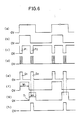
- the contact of the switch 1 is closed, whereby a current is generated between the power supply potential V cc and the ground potential, and a pulse voltage is generated at the node (a) (see the waveform (a)).
- a first voltage is inputted to the one shot multivibrators 3 and 4.
- the one shot multivibrator 3 By the voltage input, the one shot multivibrator 3 generates pulses having the pulse width R1C1, defining the pulse interval between two pulses (hereinafter referred to as double pulses) generated for one pulse voltage (see the waveform) (b)).
- the one shot multivibrator 4 generates a first pulse P1 having the width R2C2
- the multivibrator 4 When the time R1C1 is passed from the generation of the first pulse P1 and the pulse output from the multivibrator 3 falls, the multivibrator 4 generates, in response thereto, a second pulse P2 having the same pulse width as the first P1 (see the waveform (c)). In this manner, the first pulse P1 and the second pulse P2 constitute the double pulse.
- the oscillating circuit 5 outputs an oscillating waveform (see the waveform (d). It is amplified by the amplifier 6 and controls the current flowing through the transmitting coil 7 to transmit radio wave.
- the radio wave corresponding to the double pulse based on the rotation signal transmitted in this manner is detected as a voltage change by a receiving coil 9 of the receiving portion 8 shown in Fig. 1B.
- the detected voltage change is amplified by the amplifier 10 and is outputted as double pulse corresponding to the double pulse in the signal generating portion 20 (see the waveform (e)).
- the first pulse D1 constituting the double pulse is inputted to the one shot multivibrator 11 and to one input of the AND gate 13. However, since no signal is inputted to the other input portion of the AND gate 13, no signal is outputted from the output portion of the gate.
- the multivibrator 11 receiving the first pulse D1 generates a pulse having the pulse width W1 determined by the time constant R3C3 (see the waveform (f)).
- the multivibrator 12 At the fall of this pulse, the multivibrator 12 generates a pulse having the pulse width W2 determined by the time constant R4C4 (see the waveform (g)).
- the pulse width W1 and W2 are defined such that the second pulse D2 is included in the timing of generating of the pulse having the pulse width W2 generated from the multivibrator 12.
- one pulse is outputted from the AND gate 13 when the second pulse D2 of the transmitted double pulse is received (see the waveform (h)).
- This pulse is a third pulse treated at a rotation signal corresponding to the aforementioned pulse voltage. Namely, the number of pulse generation in a prescribed period of the pulse voltages indicating the number of rotation of the front wheel of a bicycle is the same as that of the third pulse. Therefore, by inputting the third pulses to a one chip microcomputer 14 used for a conventional speedometer and by counting the number of generation of the third pulses, the travel speed of the bicycle can be calculated. The result of calculation is displayed on the displaying portion 15 as needed, and by accumulating the travel speed, the travel distance can be calculated and displayed in the displaying portion 15.
- the multivibrator 11 is adapted to be not responsive to an input.
- the output of the multivibrator 12 is at the "high level" and a noise is generated from the amplifier 10 near the generation timing of the second pulse, a signal may be outputted from the AND gate 13, causing a miscount.
- FIG. 7 Another embodiment of the present invention shown in Fig. 7 is a receiving apparatus preventing such a miscount.
- This embodiment differs from the first embodiment shown in Fig. 1B in that a flipflop circuit 23 is added in the receiving portion 8.
- the transmitting apparatus may be the same as that shown in the first embodiment of Fig. 1A.
- the flipflop circuit 23 has its set input S and a reset input R connected to the output of the one shot multivibrator 11 and to the output of the AND gate 13, respectively.
- the output Q of the flipflop circuit 23 is connected to the one chip microcomputer 14 of the speedometer.
- the present invention is applied to a speedometer for a bicycle in the foregoing, the application of the spirit of this invention is not limited thereto.
- it can be applied to any apparatuses such as a wireless sphygmometer for exercise indoor and outdoor, or an apparatus for detecting rotation speed of an indoor exercise bicycle and any apparatuses which is wireless, in which signal transmission and reception with low power consumption are required and which is susceptible to external noises.
- double pulses are generated and transmission/reception are carried out based on these pulses in the foregoing, three or more pulses may be used, provided that the pulses are generated with prescribed pulse intervals. In that case, these pulses as a whole define one pulse, so that the reliability can be further improved in the transmitting-receiving apparatus.
- two or more pulse signals having prescribed pulse intervals are generated based on one input signal, and the pulse signals are transmitted and received, as described above. Therefore, even if other pulse signals are happen to be mixed because of noise and the like, such signals are not erroneously counted, whereby the reliability of the transmitting-receiving apparatus can be improved.
Landscapes
- Engineering & Computer Science (AREA)
- Physics & Mathematics (AREA)
- General Physics & Mathematics (AREA)
- Mechanical Engineering (AREA)
- Computer Networks & Wireless Communication (AREA)
- Arrangements For Transmission Of Measured Signals (AREA)
- Measuring Fluid Pressure (AREA)
- Selective Calling Equipment (AREA)
- Noise Elimination (AREA)
Applications Claiming Priority (2)
| Application Number | Priority Date | Filing Date | Title |
|---|---|---|---|
| JP147110/89 | 1989-06-10 | ||
| JP1147110A JPH0312798A (ja) | 1989-06-10 | 1989-06-10 | 無線式送受信装置 |
Publications (3)
| Publication Number | Publication Date |
|---|---|
| EP0402620A2 true EP0402620A2 (de) | 1990-12-19 |
| EP0402620A3 EP0402620A3 (de) | 1992-08-05 |
| EP0402620B1 EP0402620B1 (de) | 1997-04-23 |
Family
ID=15422749
Family Applications (1)
| Application Number | Title | Priority Date | Filing Date |
|---|---|---|---|
| EP90108653A Expired - Lifetime EP0402620B1 (de) | 1989-06-10 | 1990-05-08 | Drahtlose Sende-/Empfangsvorrichtung für ein Fahrrad |
Country Status (9)
| Country | Link |
|---|---|
| US (1) | US5170161A (de) |
| EP (1) | EP0402620B1 (de) |
| JP (1) | JPH0312798A (de) |
| KR (1) | KR930007548B1 (de) |
| AU (1) | AU627301B2 (de) |
| CA (1) | CA2017733C (de) |
| DE (1) | DE69030531T2 (de) |
| FI (1) | FI107843B (de) |
| NZ (1) | NZ233882A (de) |
Cited By (9)
| Publication number | Priority date | Publication date | Assignee | Title |
|---|---|---|---|---|
| WO1997010580A1 (en) * | 1995-09-12 | 1997-03-20 | Liberty Technologies - Beta | Apparatus for wireless transmission of shaft position information |
| EP0823267A3 (de) * | 1996-08-05 | 1998-04-08 | Jürg B. Lumpert | Sportgerät mit Datenanzeige für den Benutzer |
| EP0836165A1 (de) * | 1996-10-11 | 1998-04-15 | Polar Electro Oy | Verfahren und System zur Fernmessung |
| FR2755529A1 (fr) * | 1996-11-07 | 1998-05-07 | Mavic Sa | Systeme de commande et/ou de mesure a liaison sans fil pour cycle |
| FR2828285A1 (fr) | 2001-08-03 | 2003-02-07 | Mavic Sa | Dispositif de mesure des parametres de roulage d'une bicyclette |
| WO2006023816A1 (en) * | 2004-08-19 | 2006-03-02 | Saris Cycling Group, Inc. | Wireless wheel-speed and cadence detection method and system |
| CN101547012A (zh) * | 2008-03-24 | 2009-09-30 | 株式会社岛野 | 无线通信装备 |
| CN106297259A (zh) * | 2016-08-01 | 2017-01-04 | 西门子传感器与通讯有限公司 | 数据传输系统、变送器、接收器、数据传输方法 |
| WO2018228631A1 (de) * | 2017-06-14 | 2018-12-20 | Badass eBikes GmbH | Vorrichtung zum steuern und/oder regeln von geschwindigkeiten eines elektroleichtfahrzeugs, aufsetzbox und verfahren zur verwendung |
Families Citing this family (18)
| Publication number | Priority date | Publication date | Assignee | Title |
|---|---|---|---|---|
| AU648044B2 (en) * | 1989-10-13 | 1994-04-14 | Soothcart Pty. Limited | Container and lid arrangement |
| US5721539A (en) * | 1995-10-10 | 1998-02-24 | Goetzl; Brent A. | Speedometer for in-line skates |
| US6011491A (en) * | 1995-10-10 | 2000-01-04 | Goetzl; Brent A. | Speedometer for in-line skates |
| DE19653117C2 (de) † | 1996-12-19 | 2002-10-24 | Daniel Groos | Verfahren zur Bestimmung der Fortbewegungsgeschwindigkeit und der Bodenauflage und dazugehöriges Rad für Rollschuhe und Rollbretter |
| US6428050B1 (en) * | 1998-12-15 | 2002-08-06 | Adam K. Brandley | Motorized skate |
| DE19937155A1 (de) * | 1999-08-06 | 2001-03-15 | Bosch Gmbh Robert | System zur Erzeugung eines Signals zur Überlagerung von Informationen |
| US6937811B2 (en) * | 2002-11-19 | 2005-08-30 | Lumera Corporation | Polymer waveguide devices incorporating electro-optically active polymer clads |
| US20040224718A1 (en) * | 2003-05-09 | 2004-11-11 | Chen Yu Yu | Multifunctional body/motion signal receiving and display device |
| FI115677B (fi) * | 2003-12-19 | 2005-06-15 | Suunto Oy | Rannetietokone |
| JP2005207820A (ja) * | 2004-01-21 | 2005-08-04 | Shimano Inc | 自転車用信号出力装置及びそれを用いた自転車用走行状態表示システム |
| US8028443B2 (en) | 2005-06-27 | 2011-10-04 | Nike, Inc. | Systems for activating and/or authenticating electronic devices for operation with footwear |
| US8188868B2 (en) | 2006-04-20 | 2012-05-29 | Nike, Inc. | Systems for activating and/or authenticating electronic devices for operation with apparel |
| FR2903071B1 (fr) * | 2006-07-03 | 2009-04-17 | Salomon Sa | Dispositif de mesure de vitesse notamment pour cycle |
| US7878521B2 (en) * | 2007-04-16 | 2011-02-01 | Trek Bicycle Corporation | Bicycle frame with device cavity |
| KR100869228B1 (ko) * | 2008-03-11 | 2008-11-18 | 주식회사 드림피아 | 자전거의 주행거리 확인시스템 및 그에 따른 제어방법 |
| US20110084822A1 (en) * | 2009-10-09 | 2011-04-14 | Johnson Li | Detecting apparatus for a bicycle |
| US8384377B2 (en) * | 2009-10-30 | 2013-02-26 | Honeywell International Inc. | Self-powered magnetic tachometer for supplying a signal representative of rotational rate and absolute position |
| CN105493379A (zh) * | 2014-02-18 | 2016-04-13 | 松下知识产权经营株式会社 | 蓄电装置的控制方法、蓄电装置以及程序 |
Family Cites Families (12)
| Publication number | Priority date | Publication date | Assignee | Title |
|---|---|---|---|---|
| NL65661C (de) * | 1943-06-21 | |||
| US3257651A (en) * | 1962-04-18 | 1966-06-21 | Lyle D Feisel | Pulse position modulation information handling system |
| JPS5510040B2 (de) * | 1973-10-27 | 1980-03-13 | ||
| US3898563A (en) * | 1973-11-15 | 1975-08-05 | David E Erisman | Solid state bicycle speedometer, tachometer, and odometer device |
| US4007419A (en) * | 1975-10-02 | 1977-02-08 | Richard Jasmine | Digital bicycle speedometer-odometer |
| JPS583279B2 (ja) * | 1976-09-18 | 1983-01-20 | 株式会社リコー | パルス発受信方式 |
| NL7801649A (en) * | 1978-02-14 | 1979-08-16 | Enku Medical Systems B V | Data transmission system with measured values modulating IR beam - has receiver with two sensitive elements to distinguish between information and interference signals |
| AU540214B2 (en) * | 1979-10-16 | 1984-11-08 | State Of Victoria, The | Primary quantity electrical calibrating device |
| DE3121146A1 (de) * | 1981-05-27 | 1983-01-05 | Siemens AG, 1000 Berlin und 8000 München | Digitales funksystem |
| EP0095040B1 (de) * | 1982-05-24 | 1986-08-06 | Dieter Flasch | Geschwindigkeitsmesser für strömende Medien |
| JPS59125067A (ja) * | 1982-12-29 | 1984-07-19 | Teac Co | 速度及び方向情報の伝送方式 |
| FR2554617B1 (fr) * | 1983-11-04 | 1987-03-27 | Charbonnages De France | Procede de telecommande a vue directe d'un engin de chantier et ensemble emetteur-recepteur adapte a sa mise en oeuvre |
-
1989
- 1989-06-10 JP JP1147110A patent/JPH0312798A/ja active Pending
-
1990
- 1990-02-08 US US07/476,781 patent/US5170161A/en not_active Expired - Lifetime
- 1990-05-07 AU AU54719/90A patent/AU627301B2/en not_active Ceased
- 1990-05-08 DE DE69030531T patent/DE69030531T2/de not_active Expired - Fee Related
- 1990-05-08 EP EP90108653A patent/EP0402620B1/de not_active Expired - Lifetime
- 1990-05-29 CA CA002017733A patent/CA2017733C/en not_active Expired - Fee Related
- 1990-05-31 NZ NZ233882A patent/NZ233882A/en unknown
- 1990-06-07 KR KR1019900008312A patent/KR930007548B1/ko not_active Expired - Fee Related
- 1990-06-11 FI FI902914A patent/FI107843B/fi active IP Right Grant
Cited By (18)
| Publication number | Priority date | Publication date | Assignee | Title |
|---|---|---|---|---|
| WO1997010580A1 (en) * | 1995-09-12 | 1997-03-20 | Liberty Technologies - Beta | Apparatus for wireless transmission of shaft position information |
| EP0823267A3 (de) * | 1996-08-05 | 1998-04-08 | Jürg B. Lumpert | Sportgerät mit Datenanzeige für den Benutzer |
| EP0836165A1 (de) * | 1996-10-11 | 1998-04-15 | Polar Electro Oy | Verfahren und System zur Fernmessung |
| US6229454B1 (en) | 1996-10-11 | 2001-05-08 | Polar Electro Oy | Telemetric measuring method and system |
| FR2755529A1 (fr) * | 1996-11-07 | 1998-05-07 | Mavic Sa | Systeme de commande et/ou de mesure a liaison sans fil pour cycle |
| EP0841646A1 (de) * | 1996-11-07 | 1998-05-13 | Mavic S.A. | Drahtloses Steuerungs- und/oder Messsystem für Fahrrad |
| US6204775B1 (en) | 1996-11-07 | 2001-03-20 | Mavic S.A. | Wireless control and/or measuring system for a cycle |
| US6779401B2 (en) | 2001-08-03 | 2004-08-24 | Mavic S.A. | Device for measuring the running parameters of a bicycle |
| FR2828285A1 (fr) | 2001-08-03 | 2003-02-07 | Mavic Sa | Dispositif de mesure des parametres de roulage d'une bicyclette |
| WO2006023816A1 (en) * | 2004-08-19 | 2006-03-02 | Saris Cycling Group, Inc. | Wireless wheel-speed and cadence detection method and system |
| US7408447B2 (en) | 2004-08-19 | 2008-08-05 | Saris Cycling Group, Inc. | Wireless, passive wheel-speed and cadence detection system |
| CN101547012A (zh) * | 2008-03-24 | 2009-09-30 | 株式会社岛野 | 无线通信装备 |
| EP2129080A1 (de) * | 2008-03-24 | 2009-12-02 | Shimano, Inc. | Vorrichtung zur drahtlosen Kommunikation |
| US7761212B2 (en) | 2008-03-24 | 2010-07-20 | Shimano Inc. | Wireless communication apparatus |
| CN101547012B (zh) * | 2008-03-24 | 2016-03-16 | 株式会社岛野 | 无线通信装备 |
| CN106297259A (zh) * | 2016-08-01 | 2017-01-04 | 西门子传感器与通讯有限公司 | 数据传输系统、变送器、接收器、数据传输方法 |
| CN106297259B (zh) * | 2016-08-01 | 2019-04-30 | 西门子传感器与通讯有限公司 | 数据传输系统、数据传输方法 |
| WO2018228631A1 (de) * | 2017-06-14 | 2018-12-20 | Badass eBikes GmbH | Vorrichtung zum steuern und/oder regeln von geschwindigkeiten eines elektroleichtfahrzeugs, aufsetzbox und verfahren zur verwendung |
Also Published As
| Publication number | Publication date |
|---|---|
| JPH0312798A (ja) | 1991-01-21 |
| US5170161A (en) | 1992-12-08 |
| AU5471990A (en) | 1990-12-13 |
| FI902914A0 (fi) | 1990-06-11 |
| KR910001384A (ko) | 1991-01-30 |
| CA2017733A1 (en) | 1990-12-10 |
| KR930007548B1 (ko) | 1993-08-12 |
| HK1007211A1 (en) | 1999-04-01 |
| NZ233882A (en) | 1992-10-28 |
| DE69030531T2 (de) | 1997-09-18 |
| FI107843B (fi) | 2001-10-15 |
| CA2017733C (en) | 1994-07-26 |
| AU627301B2 (en) | 1992-08-20 |
| EP0402620B1 (de) | 1997-04-23 |
| DE69030531D1 (de) | 1997-05-28 |
| EP0402620A3 (de) | 1992-08-05 |
Similar Documents
| Publication | Publication Date | Title |
|---|---|---|
| EP0402620A2 (de) | Drahtlose Sende-/Empfangsvorrichtung für ein Fahrrad | |
| EP0420313B1 (de) | Anordnung zur Fahrzeuggeschwindigkeitsmessung über Grund mit Signalausfallkompensation | |
| US4225950A (en) | Automobile distance measuring apparatus | |
| JPH0338123B2 (de) | ||
| JPS5984472U (ja) | 自転車用計算器兼速度計装置 | |
| US5511435A (en) | Apparatus for measuring vehicle running condition | |
| US5517112A (en) | Magnetic field detector with noise blanking | |
| KR0122118B1 (ko) | 주행상태 산출장치 | |
| HK1007211B (en) | Wireless transmitting-receiving apparatus for a bicycle | |
| CN207881720U (zh) | 基于陀螺仪传感器的码表 | |
| EP0516113A2 (de) | Befestigungsanordnung für eine Scheibe und drahtlosen Drehgeschwindigkeitsdetektor | |
| US5189305A (en) | Timing apparatus particularly for racing vehicles | |
| JPH06314396A (ja) | 送受信装置 | |
| JPH06331636A (ja) | 車両用走行メーター | |
| KR102914193B1 (ko) | 빛의 왕복 시간 측정을 이용한 자전거 크랭크 수를 측정하기 위한 장치 | |
| JP2521623Y2 (ja) | 電子回転速度計 | |
| JP3362460B2 (ja) | 走行状態検出装置 | |
| EP0472539B1 (de) | Zeitnahmevorrichtung, insbesondere für rennwagen | |
| JPH0216298Y2 (de) | ||
| JPH06288775A (ja) | 自転車用ナビゲーション装置 | |
| JPH06203287A (ja) | 無線式計測装置 | |
| JP3007709B2 (ja) | 歩数計 | |
| JPH11235475A (ja) | ラジオコントロールカーの走行タイム計測装置 | |
| JPS63118608A (ja) | 走行モニタ−装置 | |
| AU5658490A (en) | Timing apparatus particularly for racing vehicles |
Legal Events
| Date | Code | Title | Description |
|---|---|---|---|
| PUAI | Public reference made under article 153(3) epc to a published international application that has entered the european phase |
Free format text: ORIGINAL CODE: 0009012 |
|
| AK | Designated contracting states |
Kind code of ref document: A2 Designated state(s): BE CH DE ES FR GB IT LI NL SE |
|
| 17P | Request for examination filed |
Effective date: 19901221 |
|
| PUAL | Search report despatched |
Free format text: ORIGINAL CODE: 0009013 |
|
| AK | Designated contracting states |
Kind code of ref document: A3 Designated state(s): BE CH DE ES FR GB IT LI NL SE |
|
| 17Q | First examination report despatched |
Effective date: 19951123 |
|
| GRAG | Despatch of communication of intention to grant |
Free format text: ORIGINAL CODE: EPIDOS AGRA |
|
| RAP1 | Party data changed (applicant data changed or rights of an application transferred) |
Owner name: CAT EYE CO., LTD. |
|
| GRAH | Despatch of communication of intention to grant a patent |
Free format text: ORIGINAL CODE: EPIDOS IGRA |
|
| GRAH | Despatch of communication of intention to grant a patent |
Free format text: ORIGINAL CODE: EPIDOS IGRA |
|
| GRAH | Despatch of communication of intention to grant a patent |
Free format text: ORIGINAL CODE: EPIDOS IGRA |
|
| GRAH | Despatch of communication of intention to grant a patent |
Free format text: ORIGINAL CODE: EPIDOS IGRA |
|
| GRAA | (expected) grant |
Free format text: ORIGINAL CODE: 0009210 |
|
| AK | Designated contracting states |
Kind code of ref document: B1 Designated state(s): BE CH DE ES FR GB IT LI NL SE |
|
| PG25 | Lapsed in a contracting state [announced via postgrant information from national office to epo] |
Ref country code: ES Free format text: THE PATENT HAS BEEN ANNULLED BY A DECISION OF A NATIONAL AUTHORITY Effective date: 19970423 Ref country code: BE Effective date: 19970423 |
|
| ITF | It: translation for a ep patent filed | ||
| REG | Reference to a national code |
Ref country code: CH Ref legal event code: NV Representative=s name: R. A. EGLI & CO. PATENTANWAELTE Ref country code: CH Ref legal event code: EP |
|
| REF | Corresponds to: |
Ref document number: 69030531 Country of ref document: DE Date of ref document: 19970528 |
|
| ET | Fr: translation filed | ||
| PLBE | No opposition filed within time limit |
Free format text: ORIGINAL CODE: 0009261 |
|
| STAA | Information on the status of an ep patent application or granted ep patent |
Free format text: STATUS: NO OPPOSITION FILED WITHIN TIME LIMIT |
|
| 26N | No opposition filed | ||
| REG | Reference to a national code |
Ref country code: GB Ref legal event code: IF02 |
|
| PGFP | Annual fee paid to national office [announced via postgrant information from national office to epo] |
Ref country code: GB Payment date: 20060503 Year of fee payment: 17 |
|
| PGFP | Annual fee paid to national office [announced via postgrant information from national office to epo] |
Ref country code: SE Payment date: 20060505 Year of fee payment: 17 |
|
| PGFP | Annual fee paid to national office [announced via postgrant information from national office to epo] |
Ref country code: DE Payment date: 20060508 Year of fee payment: 17 |
|
| PGFP | Annual fee paid to national office [announced via postgrant information from national office to epo] |
Ref country code: FR Payment date: 20060515 Year of fee payment: 17 Ref country code: CH Payment date: 20060515 Year of fee payment: 17 |
|
| PGFP | Annual fee paid to national office [announced via postgrant information from national office to epo] |
Ref country code: NL Payment date: 20060517 Year of fee payment: 17 |
|
| PGFP | Annual fee paid to national office [announced via postgrant information from national office to epo] |
Ref country code: IT Payment date: 20060531 Year of fee payment: 17 |
|
| EUG | Se: european patent has lapsed | ||
| REG | Reference to a national code |
Ref country code: CH Ref legal event code: PL |
|
| GBPC | Gb: european patent ceased through non-payment of renewal fee |
Effective date: 20070508 |
|
| PG25 | Lapsed in a contracting state [announced via postgrant information from national office to epo] |
Ref country code: NL Free format text: LAPSE BECAUSE OF NON-PAYMENT OF DUE FEES Effective date: 20071201 |
|
| NLV4 | Nl: lapsed or anulled due to non-payment of the annual fee |
Effective date: 20071201 |
|
| PG25 | Lapsed in a contracting state [announced via postgrant information from national office to epo] |
Ref country code: LI Free format text: LAPSE BECAUSE OF NON-PAYMENT OF DUE FEES Effective date: 20070531 Ref country code: CH Free format text: LAPSE BECAUSE OF NON-PAYMENT OF DUE FEES Effective date: 20070531 |
|
| REG | Reference to a national code |
Ref country code: FR Ref legal event code: ST Effective date: 20080131 |
|
| PG25 | Lapsed in a contracting state [announced via postgrant information from national office to epo] |
Ref country code: DE Free format text: LAPSE BECAUSE OF NON-PAYMENT OF DUE FEES Effective date: 20071201 |
|
| PG25 | Lapsed in a contracting state [announced via postgrant information from national office to epo] |
Ref country code: GB Free format text: LAPSE BECAUSE OF NON-PAYMENT OF DUE FEES Effective date: 20070508 |
|
| PG25 | Lapsed in a contracting state [announced via postgrant information from national office to epo] |
Ref country code: SE Free format text: LAPSE BECAUSE OF NON-PAYMENT OF DUE FEES Effective date: 20070509 |
|
| PG25 | Lapsed in a contracting state [announced via postgrant information from national office to epo] |
Ref country code: FR Free format text: LAPSE BECAUSE OF NON-PAYMENT OF DUE FEES Effective date: 20070531 |
|
| PG25 | Lapsed in a contracting state [announced via postgrant information from national office to epo] |
Ref country code: IT Free format text: LAPSE BECAUSE OF NON-PAYMENT OF DUE FEES Effective date: 20070508 |