EP0402662A2 - Verfahren und Apparat für Suspensionspolymerisation - Google Patents
Verfahren und Apparat für Suspensionspolymerisation Download PDFInfo
- Publication number
- EP0402662A2 EP0402662A2 EP90109594A EP90109594A EP0402662A2 EP 0402662 A2 EP0402662 A2 EP 0402662A2 EP 90109594 A EP90109594 A EP 90109594A EP 90109594 A EP90109594 A EP 90109594A EP 0402662 A2 EP0402662 A2 EP 0402662A2
- Authority
- EP
- European Patent Office
- Prior art keywords
- droplets
- reactor
- aqueous dispersion
- dispersion medium
- monomer liquid
- Prior art date
- Legal status (The legal status is an assumption and is not a legal conclusion. Google has not performed a legal analysis and makes no representation as to the accuracy of the status listed.)
- Granted
Links
Images




Classifications
-
- C—CHEMISTRY; METALLURGY
- C08—ORGANIC MACROMOLECULAR COMPOUNDS; THEIR PREPARATION OR CHEMICAL WORKING-UP; COMPOSITIONS BASED THEREON
- C08F—MACROMOLECULAR COMPOUNDS OBTAINED BY REACTIONS ONLY INVOLVING CARBON-TO-CARBON UNSATURATED BONDS
- C08F2/00—Processes of polymerisation
- C08F2/12—Polymerisation in non-solvents
- C08F2/16—Aqueous medium
- C08F2/18—Suspension polymerisation
-
- B—PERFORMING OPERATIONS; TRANSPORTING
- B01—PHYSICAL OR CHEMICAL PROCESSES OR APPARATUS IN GENERAL
- B01J—CHEMICAL OR PHYSICAL PROCESSES, e.g. CATALYSIS OR COLLOID CHEMISTRY; THEIR RELEVANT APPARATUS
- B01J19/00—Chemical, physical or physico-chemical processes in general; Their relevant apparatus
- B01J19/18—Stationary reactors having moving elements inside
- B01J19/1862—Stationary reactors having moving elements inside placed in series
-
- B—PERFORMING OPERATIONS; TRANSPORTING
- B01—PHYSICAL OR CHEMICAL PROCESSES OR APPARATUS IN GENERAL
- B01J—CHEMICAL OR PHYSICAL PROCESSES, e.g. CATALYSIS OR COLLOID CHEMISTRY; THEIR RELEVANT APPARATUS
- B01J19/00—Chemical, physical or physico-chemical processes in general; Their relevant apparatus
- B01J19/18—Stationary reactors having moving elements inside
- B01J19/1868—Stationary reactors having moving elements inside resulting in a loop-type movement
- B01J19/1881—Stationary reactors having moving elements inside resulting in a loop-type movement externally, i.e. the mixture leaving the vessel and subsequently re-entering it
-
- B—PERFORMING OPERATIONS; TRANSPORTING
- B01—PHYSICAL OR CHEMICAL PROCESSES OR APPARATUS IN GENERAL
- B01J—CHEMICAL OR PHYSICAL PROCESSES, e.g. CATALYSIS OR COLLOID CHEMISTRY; THEIR RELEVANT APPARATUS
- B01J4/00—Feed or outlet devices; Feed or outlet control devices
- B01J4/04—Feed or outlet devices; Feed or outlet control devices using osmotic pressure using membranes, porous plates
-
- B—PERFORMING OPERATIONS; TRANSPORTING
- B01—PHYSICAL OR CHEMICAL PROCESSES OR APPARATUS IN GENERAL
- B01J—CHEMICAL OR PHYSICAL PROCESSES, e.g. CATALYSIS OR COLLOID CHEMISTRY; THEIR RELEVANT APPARATUS
- B01J2219/00—Chemical, physical or physico-chemical processes in general; Their relevant apparatus
- B01J2219/00049—Controlling or regulating processes
- B01J2219/00051—Controlling the temperature
- B01J2219/00074—Controlling the temperature by indirect heating or cooling employing heat exchange fluids
- B01J2219/00087—Controlling the temperature by indirect heating or cooling employing heat exchange fluids with heat exchange elements outside the reactor
- B01J2219/00103—Controlling the temperature by indirect heating or cooling employing heat exchange fluids with heat exchange elements outside the reactor in a heat exchanger separate from the reactor
-
- B—PERFORMING OPERATIONS; TRANSPORTING
- B01—PHYSICAL OR CHEMICAL PROCESSES OR APPARATUS IN GENERAL
- B01J—CHEMICAL OR PHYSICAL PROCESSES, e.g. CATALYSIS OR COLLOID CHEMISTRY; THEIR RELEVANT APPARATUS
- B01J2219/00—Chemical, physical or physico-chemical processes in general; Their relevant apparatus
- B01J2219/00049—Controlling or regulating processes
- B01J2219/00051—Controlling the temperature
- B01J2219/00074—Controlling the temperature by indirect heating or cooling employing heat exchange fluids
- B01J2219/00105—Controlling the temperature by indirect heating or cooling employing heat exchange fluids part or all of the reactants being heated or cooled outside the reactor while recycling
- B01J2219/0011—Controlling the temperature by indirect heating or cooling employing heat exchange fluids part or all of the reactants being heated or cooled outside the reactor while recycling involving reactant liquids
-
- B—PERFORMING OPERATIONS; TRANSPORTING
- B01—PHYSICAL OR CHEMICAL PROCESSES OR APPARATUS IN GENERAL
- B01J—CHEMICAL OR PHYSICAL PROCESSES, e.g. CATALYSIS OR COLLOID CHEMISTRY; THEIR RELEVANT APPARATUS
- B01J2219/00—Chemical, physical or physico-chemical processes in general; Their relevant apparatus
- B01J2219/00049—Controlling or regulating processes
- B01J2219/00164—Controlling or regulating processes controlling the flow
-
- B—PERFORMING OPERATIONS; TRANSPORTING
- B01—PHYSICAL OR CHEMICAL PROCESSES OR APPARATUS IN GENERAL
- B01J—CHEMICAL OR PHYSICAL PROCESSES, e.g. CATALYSIS OR COLLOID CHEMISTRY; THEIR RELEVANT APPARATUS
- B01J2219/00—Chemical, physical or physico-chemical processes in general; Their relevant apparatus
- B01J2219/18—Details relating to the spatial orientation of the reactor
- B01J2219/182—Details relating to the spatial orientation of the reactor horizontal
Definitions
- the present invention relates to a process and an apparatus for suspension polymerization. More particularly, it relates to a process and an apparatus for suspension polymerization which can produce polymer particles having a uniform particle size.
- a suspension polymerization process which comprises steps of suspending a monomer liquid in an aqueous dispersion medium to form monomer liquid droplets in a column type reactor and then polymerizing the monomer without applying strong shear to the monomer liquid droplets, whereby the monomer can be polymerized with suppressing merging or splitting of the monomer liquid droplets.
- Japanese Patent Publication No. 36510/1978 or U.S. Patent No. 3,922,255 discloses a suspension polymerization process in which a monomer liquid is passed through an orifice to form droplets having a rather small and uniform size in an aqueous dispersion medium.
- the droplets are charged in a column type reactor, and there provided with a velocity toward a bottom of the reactor by a downflow of the aqueous dispersion medium, and the monomer liquid is partially polymerized in the reactor to such extent that the droplets are not merged or split with gentle shear.
- the partially polymerized monomer liquid droplets are discharged from the bottom of the reactor together with the aqueous dispersion medium and introduced in a solid-liquid separator which is connected with the reactor.
- the partially polymerized droplets are floatation separated and concentrated by difference of densities between the droplets and the dispersion medium.
- the separated droplets are charged in an agitated reactor and suspension polymerized with avoiding merging or splitting to give polymer particles with a considerably uniform size.
- Japanese Patent Kokai Publication No. 91701/1983 or U.S. Patent No. 4,487,898 discloses a suspension polymerization process in which a laminar flow of a monomer liquid is gushed through an orifice in an aqueous dispersion medium to form monomer droplets having a uniform size, and the droplets are charged in a column type reactor and polymerized under a fluidized condition to such extent that specific gravity of the monomer liquid droplets becomes close to that of the aqueous medium.
- a slurry comprising the partially polymerized monomer liquid droplets and the dispersion medium is circulated through the tower type reactor and a settling separator, in which the partially polymerized monomer liquid droplets having specific gravity larger than that of the dispersion medium are separated and concentrated, and then charged in a second column type reactor to further continue suspension polymerization, whereby polymer particles having a considerably uniform size are continuously produced.
- the monomer liquid droplets having a considerably uniform size are formed with the use of an orifice.
- the monomer liquid droplets having the uniform size distribution are kept in a column type reactor with forming suspension condition by a flow of an aqueous dispersion medium for a preselected period to form polymer particles having the uniform size.
- suspension condition of droplets should be kept by only a flowing of an aqueous dispersion medium in a reactor.
- the concrete agent disclosed in examples is sodium polyacrylate or a polymer protective colloid such as an animal protein gel buffered with sodium borate in pH range of 6 to 12.
- Japanese Patent Kokai Publication No. 91701/1983 also teaches that a generally used suspension and protective agent can be used, actually claimed one is a combination of an organic protective polymer colloid with an aqueous polymerization inhibitor, or a water-insoluble inorganic material.
- Japanese Patent Kokai Publication No. 102905/1982 discloses a process for suspension polymerization in which a monomer liquid is excited under vibration when the monomer liquid is gushed in an aqueous dispersion medium to form droplets having a uniform size, and then polymerized under condition where the droplets are not merged or split.
- Said Publication concretely describes only that an organic polymer material or a water-insoluble inorganic material is used as the protection agents for such condition.
- a suspension and protective agent mainly comprising the polymer protective colloid should be used in such an amount that the monomer liquid droplets are not substantially merged or split since the suspended condition of the droplets has to be maintained by the function of an aqueous dispersion medium which forms the downflow in the column type reactor.
- the aqueous dispersion medium which is separated from the polymer particles is discharged as a waste water from the process, and the waste water should be treated with a higher order treatment of waste water in order to avoid water pollution.
- a conventional suspension and protective agent mainly comprising a water-insoluble inorganic material in the form of fine powder is used instead of the polymer protective colloid.
- the water-insoluble inorganic material constituting a main component in the aqueous suspension agent is completely adsorbed on the monomer liquid droplets, whereby a concentration of the water-insoluble inorganic material in the aqueous dispersion medium is greatly reduced.
- concentration of the inorganic material is too small to protect the monomer liquid droplets which are newly charged in the reactor.
- a suspension polymerization process for production of polymer particles having a substantially uniform size comprises steps of: applying regular vibration to a flow of a monomer liquid which has a specific gravity smaller than that of an aqueous dispersion medium and which is gushed through an orifice having at least one pore in the aqueous dispersion medium containing a suspension agent which comprises a water-insoluble inorganic material to form monomer liquid droplets having a substantially uniform size, introducing the aqueous dispersion medium containing the droplets in a first reactor comprising a recycling means which discharges the aqueous dispersion medium from a bottom of the reactor and recycles it to a top of the reactor and a means for agitating the aqueous dispersion medium containing the droplets, in which reactor the aqueous dispersion medium and the droplets therein are kept at a preselected polymerization temperature, under an effect of agitation which controls an amount of the suspension agent and an effect
- an apparatus for suspension polymerization to produce polymer particles having a uniform size which apparatus comprises: a droplet forming device comprising at least one orifice having at least one pore through which a monomer liquid having a specific gravity smaller than that of an aqueous dispersion medium is gushed and a means for vibrating the gushed monomer liquid through the pore, a first reactor comprising an inlet for introducing the aqueous dispersion medium containing the formed droplets in the first reactor, a means for recycling the aqueous dispersion medium from a bottom to a top of the reactor, a means for agitating the aqueous dispersion medium containing the droplets and an outlet for discharging the aqueous dispersion medium together with partially polymerized droplets, and which reactor partially polymerizes the monomer liquid droplets introduced from the droplet forming device so that the specific gravity of the droplets do not exceed that of the aqueous dispersion medium under a pre
- the aqueous dispersion medium containing the droplets is agitated with the agitating means in the first reactor, whereby, in the first reactor, there is formed a stirred fluidized portion where suitable shear is generated between the aqueous dispersion medium and the droplets to avoid merging or splitting of the droplets.
- suspension agent comprising a conventional water-insoluble inorganic material as a main component and a polymer protective agent as a supplemental component can be used to stabilize suspension condition, instead of a polymer protective colloid which requires a higher grade treatment of waste water.
- a gentle mixing effect of the agitating means in the reactor controls an amount of the water-insoluble inorganic material which adheres to the surfaces of the monomer liquid droplets, resuspends the water-insoluble inorganic material which has excessively adhered to the droplet surfaces in the aqueous dispersion medium, and balances the amount of the water-insoluble inorganic material on the surfaces of the droplets with that suspended in the aqueous dispersion medium. Thereby the suspension condition of the droplets under polymerization is maintained.
- a concentration of the water-insoluble inorganic material in the aqueous dispersion medium which is recycled to the top of the reactor is kept at a level not less than a preselected concentration and the monomer liquid droplets newly supplied from the droplet forming device are suspended and protected by the water-insoluble inorganic material present in the aqueous dispersion medium, whereby the droplets are suspended and protected throughout a whole stirred fluidized portion in the reactor. Therefore, the problems of the prior arts are overcome and polymer particles having a more uniform size can be produced.
- stirred fluidized portion used herein is intended to mean a fluidized portion in which suspended droplets are fluidized not only by buoyancy and gravity force acting on the droplets and fluidizing effect of a dispersion medium as observed in a reactor (particularly column type reactor) during suspension polymerization, but also by an agitating effect of the agitating means. The droplets fall down gradually in the reactor.
- partially polymerized is intended to mean that a droplet is not necessarily polymerized to a preselected polymerization conversion in the first reactor (for example, polymerization is not completed in the first reactor).
- the polymerization conversion in the first reactor depends on conditions such as a kind of the monomer liquid, a particle size and a kind of the aqueous dispersion medium. However, only in the first reactor, the polymerization may be completed depending on a desired conversion. Further, the reaction which is carried out in the second reactor may be carried out in two or more steps.
- agitating means is intended to mean any means as long as it provides a mild agitating effect to maintain the fluidized condition of the monomer liquid droplets and it does not cause merging or splitting of the droplets. It is preferable to use an agitator, for example, a impeller agitator in the reactor.
- the reactor is preferably designed so that the stirred fluidized portion of the droplets can be easily kept through the effects of the aqueous dispersion medium and the agitating means.
- a tank type reactor is preferable.
- the monomer liquid is supplied to the droplet forming device through a monomer liquid feeding line and passed through the orifice having at least one pore so that droplets are formed by regular vibration in the aqueous dispersion medium which is supplied through an aqueous dispersion medium feeding line.
- a process for regularly vibrating the monomer liquid passed through a nozzle or the orifice having at least one pore to form the droplets On vibrating the monomer liquid, the vibration is, for example, applied to the monomer liquid directly or through the orifice.
- a size and a shape of the pore, a density of the pores, a kind, a frequency and an amplitude of the vibration and the like may be determined by a trial-and-error method.
- the monomer liquid used in the present invention is not limited, and is any monomer which is generally insoluble in the aqueous dispersion medium.
- vinyl compounds such as styrene, ⁇ -methylstyrene, divinylbenzene, acrylonitrile, acrylate and methacrylate and mixtures thereof are suspension polymerized according to the present invention.
- any conventional compound which is used as an initiator for radical polymerization of the vinyl monomer may be used in the form of a solution in the monomer liquid.
- examples of such polymerization initiator are organic peroxides (e.g. benzoyl peroxide, butyl perbenzoate, etc.) and azo compounds (e.g. azobisisobutyronitrile etc.).
- the monomer liquid may contain a material which can be dissolved or dispersed therein.
- the size of the monomer liquid droplets can be unified by adjusting the viscosity of the monomer liquid passed through the orifice by, for example, previously dissolving the polymer of said monomer in the monomer liquid.
- an operation range in which the uniform droplets are formed depends on a viscosity of the monomer liquid.
- the viscosity of the monomer liquid may be such that 20 % by weight of the polymer is contained in the monomer liquid.
- the suspension agent (or suspension and protective agent) is used to prevent merging or splitting of the droplets when the droplets having the uniform size are formed from the monomer liquid and also when the monomer liquid is polymerized in the polymerization reactor.
- a main component of the suspension agent is a water-insoluble inorganic material in the form of fine powder.
- water-insoluble is intended to mean a material which is hardly water-soluble and therefore, a material which is water-soluble a little can be used provided that it has a function of the suspension agent.
- main component is intended to mean a substantial component of the suspension agent .
- a weight percent of the water-insoluble inorganic material as the main component is more than 50 %, preferably more than 60 % and more preferably more than 70 % by weight of the suspension agent.
- the suspension agent may comprise a polymer protective colloid and other suspension and protective agent as an auxiliary material.
- a suitable composition of the suspension agent is determined depending on a kind of the monomer liquid and conditions of the polymerization.
- water-insoluble inorganic material examples include calcium phosphate, calcium carbonate and magnesium pyrophosphate preferably in a fine powder form.
- polystyrene resin examples include polyvinyl alcohol, methyl cellulose derivatives and polysodium acrylate.
- anionic surfactants As other suspension and protective agent, there are exemplified anionic surfactants and nonionic surfactants.
- the water-insoluble inorganic material as the main component not only prevents merging of the droplets but also adheres to the surfaces of the droplets so as to promote prevention of merging of the monomer liquid.
- the calcium phosphate fine powder is effective, and further calcium carbonate fine powder may be used in combination with calcium phosphate fine powder.
- An amount of the water-soluble inorganic material is a sum of an amount of the material which adheres to the droplets and an amount of the material which is dispersed in the aqueous medium to prevent merging of the droplets till the polymerization is finished.
- a concentration thereof in the aqueous dispersion medium filled in the reactor is not less than 0.03 %, preferably not less than 0.04 % and more preferably not less than 0.05 %, for example 0.1 % by weight before the monomer liquid is supplied in the reactor.
- the anionic surfactant is used when the function of the water-insoluble inorganic material have to be increased. ⁇ -Olefinsulfonate and alkyldiphenylsulfonate are exemplified.
- the anionic surfactant is preferably used in a concentration of 0.001 to 0.01 % by weight in the aqueous dispersion medium, but the concentration depends on amounts of the water-insoluble inorganic material and the polymer protective colloid.
- the polymer protective colloid is used when prevention of merging of the droplets of the monomer liquid should be assisted.
- An amount of the used polymer protective colloid depends on the amounts of the water-insoluble inorganic material and the anionic surfactant.
- the polymer protective colloid is preferably used in a concentration of not less than 0.001 % by weight in the aqueous dispersion medium, but the concentration should be such that the higher order treatment of waste water is not necessary.
- the polymer protective colloid tends to emulsify the monomer liquid in the aqueous dispersion medium and also to foam the aqueous dispersion medium, and therefore the amount to be used has an upper limit depending on a kind of the polymer protective colloid. Generally, more than 0.05 % by weight of the polymer protective colloid in the aqueous dispersion medium is not desirable.
- suspension and protective agent such as a nonionic surfactant can be used in combination.
- the suspension and protective agent can be used which comprises 0.03 to 0.6 % by weight of the water-insoluble inorganic material (for example, calcium phosphate), 0.003 to 0.05 % by weight of the polymer protective colloid (for example, polyvinyl alcohol) and 0.001 to 0.01 % by weight of other suspension agent (for example, sodium ⁇ -olefinsulfonate) in the aqueous dispersion medium.
- the water-insoluble inorganic material for example, calcium phosphate
- the polymer protective colloid for example, polyvinyl alcohol
- other suspension agent for example, sodium ⁇ -olefinsulfonate
- Fig. 1 shows a flow sheet of the present suspension polymerization process.
- the process according to the present invention comprises the droplet forming step, the first polymerization step and the second polymerization step.
- the apparatus according to the present invention comprises the droplet forming device 40, the first reactor 14 and the second reactor 24.
- a known device in which the monomer liquid is gushed through the orifice 3 having at least one pore in the aqueous dispersion medium to form the droplets at a tip portion of a liquid column of the monomer liquid.
- the monomer liquid is gushed through the orifice having at least one pore in the aqueous dispersion medium in the form of the liquid column under a laminar condition and then considerably uniform droplets are formed, while the aqueous dispersion medium is supplied in parallel to the gushed monomer liquid column without disturbing the formation of the uniform droplets.
- a droplet forming device which has such a mechanism that the monomer liquid is subjected to the regular vibration when it passes through the orifice having at least one pore to form the uniform droplets.
- Reasons why such device is preferably used are as follows:
- monomer droplets form the fluidized portion in a reactor by balancing buoyancy and gravity force acting on the droplets and resistance force against a flow of an aqueous dispersion medium, which is also adaptable in the stirred fluidized portion of the present invention.
- balancing depends on a size and a density of the droplet.
- the density of the droplet depends on the polymerization conversion. Therefore, the droplets are layered in the (first) reactor along a depth direction thereof so that in the upper portion of the fluidized portion, the droplets having the lower polymerization conversion are present, and in the lower portion of the reactor, the droplets having the higher polymerization conversion are present. Then, only the droplets having the higher polymerization conversion can be discharged from the lower portion of the reactor in turn.
- a relation between the polymerization conversion and a position where a droplet is located is not fixed when there is a distribution in a droplet size.
- the smaller droplets tend to be located in the upper portion of the fluidized portion and the larger droplets tend to be located in the lower portion of the fluidized portion. Then, the fixed relation between the size of the droplet and the polymerization conversion cannot be established.
- the droplet size has a fairly broad distribution as in the known case where the monomer liquid is passed through the orifice having at least one pore into the aqueous dispersion medium to form droplets at the tip portion of the liquid column, it is difficult to obtain droplets having a constant polymerization conversion from the (first) reactor.
- droplets which have been polymerized to a lower extent cannot help being supplied to the second reactor, and thereby droplets are split in the second reactor.
- droplets which are polymerized to a higher extent are separated together with the aqueous dispersion medium in the separating device, and they are recycled to the first reactor and accumulated there. Therefore, the process in which the monomer liquid is only passed through the orifice having at least one pore to form the droplets at the tip portion of the monomer liquid column is not preferred.
- the droplets having the uniform distribution can be formed, which is described in Yoshida and Nagai, "Study on Production of Uniform-sized Droplets by Mechanical Vibration”: Transactions of The Japan Society of Mechanical Engineers, 44 (401), p. 171 - 177 (1972).
- the reference describes as follows:
- the droplet forming device 40 comprises an orifice plate 3 having at least one pore, a vibration mechanism 9 and a column 4 having an inlet 6 through which the aqueous dispersion medium is introduced and an outlet 7 through which the aqueous dispersion medium containing the droplets of the monomer liquid is discharged.
- the orifice plate 3 is located in the column.
- the vibration mechanism 9 provides the vibration so that the liquid monomer column through the orifice plate 3 in the aqueous medium is regularly vibrated to form the droplets having the uniform size.
- a size of the droplet can be beforehand calculated according to the above equation and operation conditions under which the droplets are formed can be determined by estimating them from the above reference such as "Study on Production of Uniform-Sized Droplets by Mechanical Vibration" and, for example, Japanese Patent Publication No. 8296/1956 and modifying them by a trial-and-error method.
- the operating conditions are very important, and those of only the gushed velocity of the monomer liquid and the frequency of the vibration are not sufficient.
- conditions described in Japanese Patent Kokai Publication No. 120905/1982 or U.S. Patent No. 4,444,961 that is, a flow characteristics range of the gushed monomer liquid from the orifice (Reynolds number) and a frequency characteristics range (Strouhal number) are not sufficient.
- Such conditions contain a wide condition range in which no uniform droplets can be formed.
- a graph containing an amplitude of the vibration as a variable is obtained by a trial-and-error method on a diameter of the orifice pore and the frequency, which graph shows a region where substantially uniform droplets can be formed.
- the graph contains not only the flow characteristics of the monomer liquid gushed through the orifice into the aqueous dispersion medium and the frequency characteristics of the vibration but also amplitude characteristic of the vibration.
- Fig. 2 shows an example of the graph which indicates the uniform droplet forming region in the case where the vibration is provided with a pressure pulse which is described below. Under the conditions of the amplitude of the pressure pulse and the gushed velocity which are within the polygon in Fig. 2, the uniform droplets are formed.
- the vibration of a vibrator is transferred to the orifice plate (see Fig. 3).
- the vibration of the vibrator is transferred to the monomer liquid (see Fig. 4) to generate a pressure pulse.
- Fig. 3 schematically shows a sectional view of a portion near the orifice plate of the droplet forming device which is used in the present process, wherein the vibration of the vibrator is transferred to the orifice plate.
- a top portion of an orifice box 101 has the orifice plate 102 having at least one pore.
- a bottom portion is connected with a vibrating member 103 of the vibrator 111 to regularly vibrate the gushed liquid column.
- the orifice box comprises an inlet portion 104 for introducing the monomer liquid into the orifice box.
- the droplets are contacted with the aqueous dispersion medium containing a dispersion agent in a column 105 which is connected with the orifice box 101 through a diaphragm 106 so as to be filled with the aqueous dispersion medium.
- Fig. 4 schematically shows a sectional view of a portion near the orifice plate in another embodiment of the droplet forming device which can be used in the present invention.
- the vibration of the vibrator is transferred to the monomer liquid to generate the pressure pulse.
- the orifice box 101 comprises the orifice plate 102 having at least one pore as the top portion thereof to form the liquid column of the monomer in the aqueous dispersion medium 107.
- the bottom portion of the orifice box is connected concentrically, through a diaphragm 106, to a vibrating plate 110 fixed to the vibrating member 103 of the vibrator 111 in order to transfer the regular vibration to the liquid column formed through the orifice pore.
- the orifice box comprises the inlet portion 104 for introducing the monomer liquid into the orifice box 101.
- the droplets are contacted with the aqueous dispersion medium containing the dispersion agent in the column 105 which is connected with the orifice box 101 so as to be filled with the aqueous dispersion medium.
- the monomer liquid is supplied in the orifice box through a monomer liquid feeding line 1 and the monomer liquid inlet portion 2, and is formed into the droplets when the monomer liquid is passed through the orifice plate 3 into the column 4 which is filled with the aqueous dispersion medium.
- the aqueous dispersion medium is supplied in the column 4 through an aqueous dispersion medium feeding line 5 and an inlet portion 6 for introducing the aqueous dispersion medium.
- the formed droplets contact with the aqueous dispersion medium in the column, and are protected and stabilized by the function of the suspension agent contained in the aqueous dispersion medium.
- the droplets and the aqueous dispersion medium are discharged through an outlet portion 7 and a line 8, and then supplied in the first reactor 14.
- a column comprising a recycling line 13 for the aqueous dispersion medium is preferably used as shown in Fig. 5 instead of the above process.
- the aqueous dispersion medium is discharged through an outlet portion 10 located at a bottom of the column and recycled to the column through a recycling device 11 and an inlet portion 12 to form a downflow in the column, whereby sedimentation of the suspension agent on the bottom of the column is prevented.
- the downflow contacts with the droplets rising through the column with buoyancy in a counter current mode to promote stability of the droplets.
- the droplets are kept at a temperature at which polymerization is not initiated.
- the aqueous dispersion medium and the monomer droplets are preferably kept at a temperature not higher than 40 °C.
- the orifice pore is blocked with a polymerized material
- the size of the droplets is changed because a viscosity of the partially polymerized monomer liquid is increased; An amount of adsorbed suspension agent is decreased, and The protective effect of the water-insoluble inorganic material is reduced due to agglomeration thereof.
- a slurry consisting of the droplets formed in the droplet forming device 40 and the aqueous dispersion medium is supplied in the first reactor 14 which is of stirred tank type and has an inlet portion 15 located in an upper portion thereof for receiving the slurry.
- An amount ratio between the monomer liquid and the aqueous dispersion medium is selected so that no accumulation of the droplets occurs in an upper potion of the droplet forming device.
- the ratio is determined according to the diameter of the droplet. For example, when the diameter is 1 mm, the ratio of a flow rate of the aqueous dispersion medium to a flow rate of the monomer liquid is not less than 0.7. When the diameter is 0.6 mm, the ratio is not less than 1.
- the inlet portion 15 for receiving the slurry may be located in a side portion of the reactor 14, or in a lower portion of the reactor. However, the inlet is preferably located in the upper portion of the reactor. In the most preferable embodiment, as shown in Fig. 1, the slurry is supplied in the recycling line through an inlet portion 15 for the slurry and introduced together with the recycling aqueous dispersion medium in the reactor 14 through the inlet portion 20 for the aqueous dispersion medium.
- a downflow of the aqueous dispersion medium of a preselected flow rate is formed and a desired polymerization temperature is maintained by recycling the aqueous dispersion medium through an outlet portion 16 which is located in the lower portion, preferably near the bottom, a pumping device 17, a heating and cooling device 18, a recycle line 19 and the inlet portion 20 for the aqueous dispersion medium.
- the polymerization temperature is the same as the conventional suspension polymerization.
- a flow rate through the recycling line 19 is determined by a superficial velocity in the first reactor 14 as described below.
- an amount of the aqueous dispersion medium which is recycled is preferably more than that of the aqueous dispersion medium supplied through the line 8.
- the amount of the recycling aqueous dispersion medium is at least ten times, for example, thirty times, as much as that of the slurry supplied through the line 8.
- the pumping device 17 is used to achieve a desired recycling flow rate and usually any type of a pump can be used. Alternatively, a propeller is disposed in the recycling line to form a liquid flow.
- the heating and cooling device 18 is used to keep the desired polymerization temperature and usually any type of a heat exchanger can be used. Alternatively, hot water or cool water may be directly injected in the recycling line.
- a mechanism which does not generate any pulse or vibration is preferably used from a view point of stability of droplet forming and polymerization.
- a cushion tank or an accumulator is disposed in the recycling line to damp it.
- Such provision of the tank or the accumulator is particularly effective when the uniform droplets are formed by the vibrating orifice.
- Dissolved air in the aqueous dispersion medium and the monomer liquid may appear as bubbles in the reactor because of reduction of solubility of air in the medium or the monomer liquid since the temperature thereof is raised to the polymerization temperature or the monomer is polymerized. Such bubbles are not preferred from a view point of the stable polymerization.
- the aqueous dispersion medium and the monomer liquid are previously deaerated to remove the dissolved air.
- the solubility of air is increased by increasing an operation pressure in the polymerization reactor to prevent the generation of the bubbles.
- the operation pressure in the reactor can be selected depending on other polymerization conditions, and the pressure is generally not less than 2 Kg/cm2-G.
- the pressure not less than 2 Kg/cm2-G is particularly preferred for suspension polymerization of styrene.
- a head tank may be located on the recycling line 19 above the first reactor 14 so that the bubbles can rise through the inlet portion 20 for the aqueous dispersion medium and leave a polymerization system.
- Fall of the droplets is prevented by controlling a falling velocity of the aqueous dispersion medium in a region where the polymerization substantially proceeds so that the velocity is smaller than a rising velocity of the droplets due to difference between the buoyancy and the gravity force acting on the droplets, and rise of the droplets is prevented by controlling a falling velocity of the aqueous dispersion medium at the inlet portion from the droplet forming device so that the velocity is larger than the rising velocity of the droplets.
- the droplets are accumulated in the first reactor to form the stirred fluidized portion consisting of the monomer droplets and the aqueous dispersion medium with a mild flow resulted from the buoyancy of the droplets, a flow effect of the aqueous dispersion medium and a stirring effect of an agitating impeller 21.
- the polymerization proceeds in the reactor under such stirred fluidized condition.
- the linear velocity of the aqueous dispersion medium which is sufficient to form the above condition depends on the density of the monomer liquid, the diameter of the droplets, a ratio between a volume of the aqueous dispersion medium and that of the monomer liquid in the first reactor.
- the linear velocity of the aqueous dispersion medium in a straight portion of the reactor is preferably in the range of 0.1 to 1 cm/sec.
- the linear velocity of the aqueous dispersion medium at the inlet portion 20 for the aqueous dispersion medium is selected by determining a diameter of the inlet portion so that the rise of the droplets is prevented and thereby the stirred fluidized bed conditions are formed.
- the monomer droplets are not split by shear due to the flow of the aqueous dispersion medium, and also the droplets do not flow out of the first reactor with an insufficient residence time.
- the impeller 21 of the first reactor 14 is rotated so that it controls an amount of the suspension agent mainly comprising the water-insoluble inorganic material, especially the water-insoluble inorganic material, which is adsorbed on the droplets.
- the water-insoluble inorganic material is adsorbed shortly after the droplets are supplied in the first reactor. Without stirring, most of the water-insoluble inorganic material which is present in the reactor is adsorbed on the droplets. As a result, a concentration of the water-insoluble inorganic material suspended in the aqueous dispersion medium leaving the outlet portion 16 is drastically reduced. Such aqueous dispersion medium is recycled through the recycling line 19 to the first reactor. Thus, even if the recycled aqueous dispersion medium is mixed with the aqueous dispersion medium which is newly supplied from the droplet forming device, the concentration of the water-insoluble inorganic material is very small after mixing, and such small concentration is not sufficient to keep the droplets stably. Therefore, the water-insoluble inorganic material which is excessively adsorbed on the droplets should be re-dispersed in the aqueous dispersion medium in the first reactor.
- An agitating speed of the impeller 21 fixed to the first reactor 14 is determined with considerations on the reduction of the concentration of the water-insoluble inorganic material as described above and on the prevention of splitting of the droplets by the impeller 21.
- a shape of the first reactor 14 is such that a cross-sectional area perpendicular to a flowing direction of the aqueous dispersion medium of the first reactor is reduced along the direction towards the upper portion of the reactor.
- the first reactor is in the form of a cone or comprises a plurality of columns an upper column of which has a smaller diameter than that of an adjacent lower column.
- the reactor may be a stirred tank type one equipped with an agitator to control the adsorption of the suspension agent on the droplets.
- the stirred fluidized portion in the first reactor gradually gets longer during continuing to supply the droplets in the first reactor and the lower end of the fluidized portion reaches an outlet portion 22 for slurry recovery which is located in the lower portion of the first reactor.
- the slurry containing the droplets having a desired polymerization conversion can be taken out when the outlet portion 22 is located at a preselected position so as to make the residence time of the droplets correspond to a desired polymerization period and the polymerization is carried out during the residence time. Then, the slurry is supplied in the second reactor 24 to continue or finish the polymerization.
- the stirred fluidized portion is formed in the first reactor by controlling the superficial velocity of the aqueous dispersion medium in the range of 0.1 to 1 cm/sec. in the straight portion of the reactor.
- the droplets are layered in the first reactor so that the polymerization conversion of the droplets increases as they are located in a lower position in the stirred fluidized portion.
- the lower portion of the reactor only the droplets having the higher polymerization conversion aggregate. As a result, a distribution of the polymerization conversion of the droplets discharged from the outlet portion for the slurry recovery is sharp.
- Japanese Patent Publication No. 36510/1978 describes a process in which a linear velocity of an aqueous dispersion medium in a straight portion of a reactor is not controlled so that it is smaller than a rising linear velocity of droplets due to difference between buoyancy and specific gravity of the droplets, so that the droplets are provided with a substantial falling velocity by a downflow of the aqueous dispersion medium.
- the droplets discharged from a first reactor have a broad distribution of a polymerization conversion when the droplets have a size distribution.
- the linear velocity of the aqueous dispersion medium in the lower portion of the reactor should be smaller than that in a portion above said lower portion.
- the linear velocity is preferably not larger than 0.3 cm/sec.
- the lower portion of the first reactor 14 is constructed from a plurality of columns having such diameters that a diameter of a lower column is larger than that of an upper one just above said lower one.
- the lower portion of the first reactor is in the form of a cone such that a lower portion has a larger diameter.
- the droplets which has been polymerized to a preselected polymerization conversion are discharged from the lower portion of the first reactor 14, and supplied in the second reactor 24 through a line 23.
- the polymerization conversion of the droplets in the slurry discharged from the first reactor 14 is generally not larger than 45 %, preferably not larger than 40 %.
- the specific gravity of the droplet closely approaches to that of the aqueous dispersion medium. Then, the droplet tends be entrained with the recycling aqueous dispersion medium. This requires a liquid-solid separator which is specifically designed to recover the entrained droplets. This is not desirable since the operations becomes complicated and inconvenient.
- the polymerization conversion of the droplets discharged from the first reactor can be determined by a trial-and-error method depending on a kind of the monomer liquid and polymerization conditions, and is generally not less than 20 %, preferably not less than 25 %. When the conversion is less than 20 %, the droplet tends to be split under the polymerization conditions in the second reactor 24, whereby it is difficult to perform polymerization in the second reactor.
- the droplets are discharged from the first reactor through the outlet portion 22 for discharging (recovering) the slurry.
- the outlet portion is preferably located above the outlet portion 16 for the aqueous dispersion medium.
- a separate recovery tank 35 may be disposed between the outlet portion 16 for the aqueous dispersion medium and the recycling device 17.
- the tank comprises an inlet portion 33 for the aqueous dispersion medium entraining the droplets, an outlet portion 22 for recovering the slurry containing the droplets and an outlet portion 34 for the recycling aqueous dispersion medium 34.
- the recovering tank 35 recovers the droplets by a floatation method using density difference between the droplet and the aqueous dispersion medium.
- Those skilled in the art can easily design the tank an upper portion of which is in the form of a cone.
- the linear velocity of the aqueous dispersion medium in the tank is controlled at less than 0.3 cm/sec. so that the no droplet is entrained with the aqueous dispersion medium.
- the stirred fluidized portion is formed and also the distribution of the droplet size is sharp.
- the droplets in the first reactor are arranged so that the polymerization conversion gets higher along a direction from the upper portion towards the lower portion of the stirred fluidized portion in the reactor.
- the lower portion of the reactor only the droplets having the highest polymerization conversion aggregate.
- the superficial velocity of the aqueous dispersion medium in the straight portion of the reactor is controlled to 0.1 to 1 cm/sec., which is smaller than the rising velocity of the droplets based on the difference between the buoyancy and the gravity force.
- the outlet portion 22 for discharging the droplets When the outlet portion 22 for discharging the droplets is located above the outlet portion 16 for recycling the aqueous dispersion medium, a portion in which only the aqueous dispersion medium not containing and separated from the monomer liquid droplets is present is formed between the outlet portions 16 and 22. Thus, the slurry containing the droplets is separated from the aqueous dispersion medium to be recycled without a specific separator (or a recovery tank).
- the droplets supplied in the second reactor 24 through the inlet portion 27 for the slurry are mixed with an agitator 25 till a desired polymerization conversion is reached, and then recovered from an outlet portion 26 as polymer particles having a uniform size.
- the agitating speed must not provide shear force to form droplets in a stirred tank reactor, and only have to keep the droplets mixed or suspended. This is a different feature from the conventional suspension polymerization.
- the agitating speed of the impeller 25 in the second reactor 24 is preferably not larger than 90 cm/sec. expressed as the speed of the impeller tip portion till the polymerization conversion becomes 60 %.
- the second reactor 24 is a conventional reactor in the form of a stirred tank and some examples thereof will be described below.
- At least two reactors of the stirred tank type can be used as the second reactors by using them alternatively (see Fig. 6).
- the second reactor is constructed from a plurality of reactors of the stirred take type which are adjacently connected each other so that the droplets are transferred from one reactor to the adjacent one.
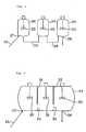
- Fig. 7 shows a row of three reactors which are connected with lines 29.
- a reactor which comprises at least one partition 32 having at least one opening 30 to form a row of a stirred tank chambers can work as the connected reactors for the second reactor as described above.
- Fig. 8 shows a stirred tank reactor comprising the three mixing chambers.
- the droplets from the first reactor are polymerized in an upper portion of the second reactor which comprises an agitating means 31 in said upper portion during the specific gravity of the droplets is smaller than that of the aqueous dispersion medium.
- the specific gravity of the droplets becomes equal to that of the aqueous dispersion medium, the droplets settle in a lower portion of the reactor. Then the settling droplets are entrained out of the reactor with the aqueous dispersion medium and supplied in a subsequent reactor of the stirred tank type, in which the polymerization is completed.
- Fig. 9 shows one embodiment in which three stirred tanks are combined to finish the polymerization.
- the polymerization reactors are preferably operated continuously since the droplet forming device is also operated continuously.
- the batchwise polymerization is of course possible.
- the batchwise polymerization can be carried out as follows:
- the aqueous dispersion medium is at an ordinary temperature.
- the slurry comprising the monomer liquid droplets and the aqueous dispersion medium is supplied in a necessary amount to the first reactor. Then, the slurry kept at a desired temperature is subjected to polymerization operation in the first reactor till the specific gravity of the droplets approaches to that of the aqueous dispersion medium.
- the droplets in the first reactor are transferred together with the aqueous dispersion medium to a second reactor where the polymerization is finished batchwise before they flow out of the first reactor.
- the slurry comprising the droplets and the aqueous dispersion medium is recovered from the outlet portion 26 for recovery when the polymerization is finished.
- the droplets is recovered as polymer particles with a conventional dewatering process. Such particles may be further treated.
- a monomer liquid comprising styrene as a main component is suspension polymerized to produce polymer particles having a uniform size. Then, the particles are suspended in water, to which styrene or a monomer liquid comprising styrene as a main component is further added continuously or portion by portion to enlarge the size of the particles. As a result, the polymer particles having a larger uniform size can be produced.
- the styrene based particles having the uniform size produced by suspension polymerization of the present invention are suspended in water, to which a foaming agent is added to produce styrene based expandable polymer particles.
- the styrene based particles having the uniform size are suspended in water, to which styrene or a monomer liquid comprising styrene as a main component is supplied continuously or intermittently to further proceed the polymerization and the foaming agent is also added during or after the polymerization to produce styrene based expandable polymer beads having a larger uniform size.
- the droplets which have the uniform size and the smaller specific gravity than that of the aqueous dispersion medium; the stirred fluidized portion is formed in the first reactor by means of the agitating effect of the agitating means and the flow effect of the aqueous dispersion medium which is recycled through the first reactor; and the water-insoluble inorganic material (or the suspension agent comprising the inorganic material as a main component) adsorbed on the droplets is controlled with the agitating effect to balance the amount of the inorganic material on the droplets and that in the aqueous dispersion medium, whereby the droplets in the stirred fluidized portion are protected under suspension condition as a whole.
- the conventional dispersion agent comprising the water-insoluble inorganic material as a main component can be used instead of the suspension and protective agent which requires the higher order treatment of waste water to form stably the droplets having the uniform size.
- the droplet forming device as shown in Fig. 5 was used. Droplets containing styrene and benzoyl peroxide were formed in the aqueous dispersion medium.
- the orifice box comprising the orifice plate 3 made . of stainless steel having three pores was disposed in the column 4. A diameter of the pore was 0.25 mm.
- the orifice box was mechanically connected with the vibrator 9.
- the vibrator was operated at a frequency of 600 Hz to form droplets of the monomer liquid in the aqueous dispersion medium.
- the droplet forming device was filled with the aqueous dispersion medium, which was discharged from the bottom 10 and recycled by a pump 11 to the upper portion 12 of the column 4 at a flow rate of 4.8 l/hr. so that a downflow of the aqueous dispersion medium was formed in the column to prevent sedimentation of the suspension agent.
- the aqueous dispersion medium was supplied in the recycling line 6 through a line 5 at a flow rate of 1.6 l/hr.
- the aqueous dispersion medium was ion-exchanged water comprising 0.1 % by weight of calcium phosphate fine powder, 0.0045 % by weight of sodium ⁇ -olefinsulfonate, 0.013 % by weight of polyvinyl alcohol and 0.006 % by weight of sodium nitrite and was previously deaerated.
- styrene containing 0.26 parts by weight of benzoyl peroxide to 100 parts by weight of styrene was supplied to the orifice box at a flow rate of 0.8 l/hr. through a line 1 after deaeration.
- the polymerization apparatus was the same as shown in Fig. 1.
- the slurry which left the droplet forming device 30 at ordinary temperature was supplied in the recycling line 19 for the aqueous dispersion medium at 15 above the first reactor 15, and then supplied in the first reactor through the inlet portion 20 for the aqueous dispersion medium.
- the first reactor comprised two cylindrical portions connected with a portion in the form of a truncated cone with a height of 74 mm.
- One cylindrical portion had a diameter of 85 mm and a height of 700 mm and the other had a diameter of 127 mm and a height of 300 mm.
- the first reactor further comprised a conical portion as its top portion and a bottom of the reactor was flat.
- An impeller 21 with a diameter of 50 mm was inserted in the reactor from below.
- the slurry containing the droplets was introduced into the first reactor, it was filled with the aqueous dispersion medium, which was recycled through the first reactor with a centrifugal pump.
- the flow rate of the recycling medium was controlled so that the droplets did not flow back through the inlet 20 for the aqueous dispersion medium and the stirred fluidized portion was formed in the first reactor.
- the recycling amount of the aqueous dispersion medium was controlled so that a superficial velocity of the aqueous dispersion medium was 6.8 cm/sec. at the inlet portion 20 for the medium in the upper portion of the reactor, and also so that 0.44 cm/sec. in the cylindrical portion with a diameter of 85 mm.
- the amount of the recycling medium was 1.5 l/min., and 37.5 times as much as the slurry containing the droplets supplied from the droplet forming device.
- a temperature of the recycling medium was controlled to be 90 °C with the heat exchanger 18 equipped on the recycling line 19.
- the droplets which reached the outlet portion 22 were discharged and supplied in the second reactor 24.
- the polymerization conversion of the droplets discharged from the first reactor was 36 %.
- the second reactor was equipped with an impeller 25 and baffle plates.
- the impeller was rotated at 75 cm/sec. of an agitating speed of the impeller tip.
- a diameter of the reactor was 140 mm and an equivalent liquid depth thereof was 250 mm.
- the slurry supply was stopped and the polymerization was carried out at a temperature of 90 °C for three hours.
- the polymerization conversion of the polymer particles from the second reactor was 92 %.
- a size distribution of the particles is shown in Table 1.
- Table 1 Size distribution of particles
- Diameter range (mm) ⁇ 1 1 - 0.84 0.84 - 0.5 ⁇ 0.5 Weight fraction (%) 0.2 0.3 99.4 0.1 (Classification with Tylar standard sieve)
- Example 2 The polymerization of styrene was repeated as in Example 1 except that the monomer liquid was not subjected to the mechanical vibration in the droplet forming device.
- a classified fluidized condition was formed so that droplets having a larger size were present in an upper portion of the first reactor, and droplets having a smaller size in a lower portion.
- the polymerization was continued at such an amount of the recycling aqueous dispersion medium that the droplets did not flow back through the inlet portion for the aqueous dispersion medium.
- small droplets began to flow out of the first reactor with the aqueous dispersion medium to the second reactor.
- the droplets could not remain in the first reactor for a desired period.
- the sizes of the droplets were highly scattered.
- Example 2 The polymerization of styrene was repeated as in Example 1 except that the recycling amount of the aqueous dispersion medium was 5 l/min. (therefore, a superficial velocity in the cylindrical portion with a diameter of 85 mm of the first reactor was 1.3 cm/sec.).
- the superficial velocity exceeded the rising velocity determined with the density difference between the droplet and the aqueous dispersion medium. Then, vigorous mixing is occurred in top portion of the first reactor. A fraction of the droplets in the first reactor was reduced and most of the droplets flowed out of the first reactor, whereby it was impossible to keep the fluidized portion in the first reactor.
- Example 2 The polymerization of styrene was repeated as in Example 1 except that the monomer liquid and the aqueous dispersion medium were not deaerated and the operating pressure in the first reactor was increased to 2 Kg/cm2-G with air.
- the bubbles were generated after 2.5 hours from the initiation of the polymerization.
- the bubbles aggregated in the upper portion of the first reactor, whereby the polymerization proceeded unstably.
- Example 2 The polymerization of styrene was repeated as in Example 1 except that the amount of the aqueous dispersion medium supplied in the droplet forming device was 15 l/hr.
- the recycling amount of the aqueous dispersion medium was 1.5 l/min. and it was five times as much as the amount of the slurry containing the monomer droplets supplied in the first reactor.
- the slurry was at a temperature of 30 °C. Then, the temperature of the recycling medium was controlled as in Example 1, and then the temperature in the first reactor was decreased to 81 °C. In order to increase the temperature in the reactor to 90 °C, the following three methods were carried out.
- the slurry temperature supplied in the first reactor was increased to 81 °C by heating the aqueous dispersion medium supplied in the droplet forming device. Then, not only the formed droplets were unstably dispersed, but also polymerization of the monomer liquid was occurred near the orifice.
- the temperature of the recycling aqueous dispersion medium through the first reactor was increased. However, the bubbles were much generated when the temperature was increased to 95 °C and the fluidized portion was filled with the bubbles, which made the operation impossible.
- the operating pressure in the first reactor was increased to 2.5 Kg/cm2-G so that the temperature of the recycling aqueous dispersion medium might be increased.
- the temperature in the first reactor was controlled to be 90 °C and the polymerization could be possible.
- the slurry discharged from the first reactor and supplied in the second reactor was in a flow rate of 15.8 l/hr., since the slurry was supplied in the first reactor in a flow rate of 15.8 l/hr. (the aqueous dispersion medium in the slurry: 15 l/hr., the monomer liquid in the slurry: 0.8 l/hr.).
- Example 2 The polymerization of styrene was repeated as in Example 1 except that the agitating speed of the impeller in the first reactor was set to 16 cm/sec.
- Example 2 The polymerization of styrene was repeated as in Example 1 except that the recycling amount of the aqueous dispersion medium through the first reactor was 1.1 l/min.
- a superficial velocity in the cylindrical portion with a diameter of 85 mm was 0.32 mm/sec.
- the end portion of the fluidized portion was reached the outlet portion for the droplets, and then the droplets were supplied in the second reactor through the outlet portion.
- the polymerization conversion of the droplets from the first reactor was 46 % and a portion of the droplets were entrained in the recycling line.
- the polymerization of styrene was repeated as in Example 1 except that the second reactor was fully filled with the aqueous dispersion medium and a different reactor system was used as the second reactor.
- the reactor system comprised a reactor of the stirred tank type (diameter: 140 mm, equivalent liquid depth: 80 mm) in the upper portion of which an impeller is disposed at a position of 65 mm from the bottom and a horizontally long reactor as shown in Fig. 8.
- the long reactor was constituted from five chambers, adjacent two chambers of which were separated with a partition having an opening of 4 mm in diameter in the lower portion.
- the chamber had a horizontal cross section of a square shape having a side of 125 mm and an equivalent depth of 140 mm.
- the long reactor had an agitating means in each chamber.
- the agitating speed of the agitator was 16 cm/sec. in the first, the second and the third chambers and 24 cm/sec. in the fourth and fifth chambers.
- the polymerization was carried out continuously through the whole operation and the polymer particles were continuously obtained from the last chamber of the long reactor.
- the polymerization conversion of the polymer particles was 90 %.
- a size distribution of the particles is shown in Table 2.
- Table 2 Size distribution of polymer particles
- Table 2 Size distribution of polymer particles
- Diameter range (mm) ⁇ 1 1 - 0.84 0.84 - 0.5 ⁇ 0.5 Weight fraction (%) 0.3 0.6 99.0 0.1
- the polymerization of styrene was carried out using the droplet forming device as shown in Fig. 5. Droplets containing styrene and benzoyl peroxide were formed in the aqueous dispersion medium.
- the orifice box comprising the orifice plate 3 made of stainless steel with four pores was disposed in the column 4. A diameter of the pore was 0.17 mm.
- the orifice box was mechanically connected with the vibrator 9.
- the vibrator was operated at a frequency of 950 Hz to form droplets of the monomer liquid in the aqueous dispersion medium.
- the droplet forming device was filled with the aqueous dispersion medium, which was discharged from the bottom 10 and recycled by a pump 11 to the upper portion 12 of the column 4 at a flow rate of 4 l/hr. so that the downflow of the aqueous dispersion medium was formed in the column to prevent sedimentation of the suspension agent.
- the aqueous dispersion medium was supplied in the recycling line 6 through a line 5 at a flow rate of 1.32 l/hr.
- the aqueous dispersion medium was ion-exchanged water comprising 0.1 % by weight of calcium phosphate fine powder, 0.0045 % by weight of sodium ⁇ -olefinsulfonate, 0.013 % by weight of polyvinyl alcohol and 0.006 % by weight of sodium nitrite and was previously deaerated.
- styrene containing 0.26 parts by weight of benzoyl peroxide to 100 parts by weight of styrene was supplied to the orifice box at a flow rate of 0.66 l/hr. through a line 1 after deaeration.
- the polymerization process was the same as shown in Fig. 1 except the second reactor.
- the slurry which left the droplet forming device 30 at ordinary temperature was supplied in a recycling line 19 for the aqueous dispersion medium at 15 above the first reactor 15, and then supplied in the first reactor through the inlet 20 for the aqueous dispersion medium.
- the first reactor comprised two cylindrical portions connected with a portion in the form of a truncated cone with a height of 74 mm.
- One cylindrical portion had a diameter of 85 mm and a height of 700 mm and the other had a diameter of 127 mm and a height of 300 mm.
- the first reactor further comprised a conical portion as its top portion and the bottom of the reactor was flat.
- An impeller 21 with a diameter of 50 mm was inserted in the reactor from below.
- the slurry containing the droplets was introduced into the first reactor, it was filled with the aqueous dispersion medium, which was recycled through the first reactor with the centrifugal pump.
- the flow rate of the recycling medium was controlled so that the droplets did not flow back through the inlet 20 for the aqueous dispersion medium and the stirred fluidized portion was formed in the first reactor.
- the recycling amount of the aqueous dispersion medium was controlled so that a superficial velocity of the aqueous dispersion medium was 6.8 cm/sec. at the inlet portion 20 for the medium in the upper portion of the reactor, and also so that 0.44 cm/sec. in the cylindrical portion with a diameter of 85 mm.
- the amount of the recycling medium was 1.5 l/min., and 46.9 times as much as the slurry containing the droplets supplied from the droplet forming device.
- a temperature of the recycling medium was controlled to be 90 °C with the heat exchanger 18 equipped on the recycling line 19.
- the droplets which reached the outlet portion 22 were discharged and supplied in the second reactor 24.
- the polymerization conversion of the droplets discharged from the first reactor was 35 %.
- the second reactor was the same horizontally long type as used in Example 3.
- the reactor was constituted from ten chambers, adjacent two chambers of which were separated with a partition having an opening of 4 mm in diameter in the lower portion.
- Each chamber had a horizontal cross section of the square shape having a side of 125 mm and an equivalent depth of 140 mm.
- the long reactor had a agitating means in each chamber.
- the agitating speed of the agitator was 16 cm/sec. in the first, the second and the third chambers and 24 cm/sec. in the other chambers.
- An average residence time in the second reactor was nine hours.
- the polymerization was finished at 90 °C.
- the polymerization conversion of the polymer particles was 95 %.
- a size distribution of the particles is shown in Table 3.
- Table 3 Size distribution of particles
- Diameter range (mm) ⁇ 0.84 0.84-0.59 0.59-0.35 ⁇ 0.35
- Weight fraction (%) 0.3 0.5 99.1 0.1 (Classification with Tylar standard sieve)
- the beads were matured for five days at 20 °C, and then a volatilizable residue was determined to be about 6.5 %.
- the beads were heated in a steamer for three minutes and expanded polystyrene beads were obtained.
- a suspension agent which requires a higher order treatment of waste water has been necessarily used.
- a conventional dispersion agent can be used which comprises an water-insoluble inorganic material as a main component to obtain polymer particles having a uniform size.
- a suspension polymerization process for production of polymer particles having a substantially uniform size comprises steps of: applying regular vibration to a flow of a monomer liquid which has a specific gravity smaller than that of an aqueous dispersion medium and which is gushed through an orifice having at least one pore in the aqueous dispersion medium containing a suspension agent which comprises a water-insoluble inorganic material to form monomer liquid droplets having a substantially uniform size, introducing the aqueous dispersion medium containing the droplets in a first reactor comprising a recycling means which discharges the aqueous dispersion medium from a bottom of the first reactor and recycles it to a top of the reactor and a means for agitating the aqueous dispersion medium containing the droplets, in which reactor the aqueous dispersion medium and the droplets therein are kept at a preselected polymerization temperature, under an effect of agitation which controls an amount of the suspension agent and an effect of the recycling aqueous disper
- liquid monomer mainly comprises styrene.
- a suspension polymerization process of styrene comprising suspending the polymer particles produced by the process according to embodiment 14 or 15 to form a suspension, adding styrene or a monomer liquid mainly comprising styrene in the suspension continuously or portion by portion to further polymerize, and recovering styrene based polymer particles having a uniform size.
- a suspension polymerization process of styrene comprising suspending the polymer particles produced by the process according to embodiment 14 or 15 to form a suspension, adding a foaming agent in the suspension during or after the polymerization, and recovering styrene based expandable polymer particles having a uniform size.
- a suspension polymerization process of styrene comprising suspending the polymer particles produced by the process according to embodiment 14 or 15 to form a suspension, adding styrene or a monomer liquid mainly comprising styrene in the suspension continuously or portion by portion to further polymerize, and adding a foaming agent in the suspension during or after the polymerization, and recovering styrene based expandable polymer particles having a uniform size.
- An apparatus for suspension polymerization to produce polymer particles having a uniform size which apparatus comprises: a droplet forming device comprising at least one orifice having at least one pore through which a monomer liquid having a specific gravity smaller than that of an aqueous dispersion medium is gushed and a means for vibrating the gushed monomer liquid through the pore, a first reactor comprising an inlet for introducing the aqueous dispersion medium containing the formed droplets in the first reactor, a means for recycling the aqueous dispersion medium from a bottom to a top of the reactor, a means for agitating the aqueous dispersion medium containing the droplets and an outlet, which is located above a means from which the recycling means discharges the aqueous dispersion medium, for discharging the aqueous dispersion medium together with partially polymerized droplets, and which reactor partially polymerizes the monomer liquid droplets introduced from the droplet forming device so that the specific gravity of the droplets do not exceed that
- the droplet forming device further comprises a recycling line to form a downflow of the recycling aqueous dispersion medium in the device.
- the second reactor comprises at least one stirred tank type reactor.
- the second reactor comprises at least one stirred tank type reactor having at least one partition with an opening to separate the reactor to form at least two chambers.
- At least one second reactor comprises an impeller for a slow speed agitation and said reactor is of a stirred tank type such that it is filled with the aqueous dispersion medium and the monomer droplets to carry out the polymerization till the specific gravity of the droplets is equal to that of the aqueous dispersion medium.
Landscapes
- Chemical & Material Sciences (AREA)
- Organic Chemistry (AREA)
- Chemical Kinetics & Catalysis (AREA)
- Health & Medical Sciences (AREA)
- Medicinal Chemistry (AREA)
- Polymers & Plastics (AREA)
- Polymerisation Methods In General (AREA)
Applications Claiming Priority (2)
| Application Number | Priority Date | Filing Date | Title |
|---|---|---|---|
| JP12808389A JPH0832728B2 (ja) | 1989-05-22 | 1989-05-22 | 懸濁重合方法および装置 |
| JP128083/89 | 1989-05-22 |
Publications (3)
| Publication Number | Publication Date |
|---|---|
| EP0402662A2 true EP0402662A2 (de) | 1990-12-19 |
| EP0402662A3 EP0402662A3 (de) | 1991-08-14 |
| EP0402662B1 EP0402662B1 (de) | 1996-04-17 |
Family
ID=14975991
Family Applications (1)
| Application Number | Title | Priority Date | Filing Date |
|---|---|---|---|
| EP19900109594 Expired - Lifetime EP0402662B1 (de) | 1989-05-22 | 1990-05-21 | Verfahren und Apparat für Suspensionspolymerisation |
Country Status (3)
| Country | Link |
|---|---|
| EP (1) | EP0402662B1 (de) |
| JP (1) | JPH0832728B2 (de) |
| DE (1) | DE69026533D1 (de) |
Cited By (5)
| Publication number | Priority date | Publication date | Assignee | Title |
|---|---|---|---|---|
| EP0526741A3 (de) * | 1991-07-05 | 1993-02-24 | Shin-Etsu Chemical Co., Ltd. | Reaktorsystem für die Suspensionspolymerisation von Vinyl-Chlorid |
| US5686048A (en) * | 1994-11-14 | 1997-11-11 | Hanwha Chemical Corporation | Agitator for suspension polymerization of vinyl chloride and suspension polymerization method using the same |
| US7087204B2 (en) * | 2001-01-29 | 2006-08-08 | Toyo Engineering Corporation | Reaction unit |
| US10370461B2 (en) | 2013-07-31 | 2019-08-06 | Basf Se | Reverse-phase polymerization process |
| CN119334700A (zh) * | 2024-12-19 | 2025-01-21 | 嘉兴迪肯特化工机械有限公司 | 一种聚酯多元醇釜在线真空取样设备 |
Families Citing this family (3)
| Publication number | Priority date | Publication date | Assignee | Title |
|---|---|---|---|---|
| JP2008095115A (ja) * | 2001-06-22 | 2008-04-24 | Sekisui Chem Co Ltd | 樹脂微粒子の製造方法、樹脂微粒子及び樹脂微粒子の製造装置 |
| US8816026B2 (en) * | 2012-09-20 | 2014-08-26 | Thermax Limited | Method and apparatus for preparing polymer beads of uniform particle size by suspension polymerisation |
| CN103331125B (zh) * | 2013-07-23 | 2015-07-15 | 重庆大学 | 高精度配气仪 |
Family Cites Families (2)
| Publication number | Priority date | Publication date | Assignee | Title |
|---|---|---|---|---|
| GB1410832A (en) * | 1973-01-23 | 1975-10-22 | Shell Int Research | Process for continuous polymer preparation |
| US4487898A (en) * | 1981-06-12 | 1984-12-11 | Kanegafuchi Chemical Industry Co., Ltd. | Process of continuous suspension polymerization |
-
1989
- 1989-05-22 JP JP12808389A patent/JPH0832728B2/ja not_active Expired - Lifetime
-
1990
- 1990-05-21 EP EP19900109594 patent/EP0402662B1/de not_active Expired - Lifetime
- 1990-05-21 DE DE69026533T patent/DE69026533D1/de not_active Expired - Lifetime
Cited By (5)
| Publication number | Priority date | Publication date | Assignee | Title |
|---|---|---|---|---|
| EP0526741A3 (de) * | 1991-07-05 | 1993-02-24 | Shin-Etsu Chemical Co., Ltd. | Reaktorsystem für die Suspensionspolymerisation von Vinyl-Chlorid |
| US5686048A (en) * | 1994-11-14 | 1997-11-11 | Hanwha Chemical Corporation | Agitator for suspension polymerization of vinyl chloride and suspension polymerization method using the same |
| US7087204B2 (en) * | 2001-01-29 | 2006-08-08 | Toyo Engineering Corporation | Reaction unit |
| US10370461B2 (en) | 2013-07-31 | 2019-08-06 | Basf Se | Reverse-phase polymerization process |
| CN119334700A (zh) * | 2024-12-19 | 2025-01-21 | 嘉兴迪肯特化工机械有限公司 | 一种聚酯多元醇釜在线真空取样设备 |
Also Published As
| Publication number | Publication date |
|---|---|
| EP0402662A3 (de) | 1991-08-14 |
| JPH0832728B2 (ja) | 1996-03-29 |
| JPH02305802A (ja) | 1990-12-19 |
| DE69026533D1 (de) | 1996-05-23 |
| EP0402662B1 (de) | 1996-04-17 |
Similar Documents
| Publication | Publication Date | Title |
|---|---|---|
| US5276113A (en) | Process for suspension polymerization | |
| JP2715029B2 (ja) | ポリマービーズ | |
| EP0067415B1 (de) | Verfahren zur kontinuierlichen Suspensionspolymerisation | |
| EP0271922B1 (de) | Verfahren zur Suspensionspolymerisation | |
| US6391985B1 (en) | High condensing mode polyolefin production under turbulent conditions in a fluidized bed | |
| EP1408053A1 (de) | Kontrollierte Suspensionspolymerisationverfahren ohne mechanisches Rühren | |
| EP2711074B1 (de) | Verfahren und Vorrichtung zur Herstellung von Polymerkügelchen mit gleichmäßiger Partikelgröße durch Suspensionspolymerisation | |
| EP0402662B1 (de) | Verfahren und Apparat für Suspensionspolymerisation | |
| CA1203345A (en) | Method of continuous polymerization in fluidized bed | |
| EP0432508B1 (de) | Verfahren zur Herstellung einer Öl-in-Wasser-Dispersion mit gleichförmigen flüssigen Teilchen und Verfahren zur Herstellung von gleichförmigen Polymerperlen | |
| KR100191378B1 (ko) | 비닐 클로라이드 수지를 제조하기위한 미세현탁중합법 | |
| US6277333B1 (en) | Process for reducing or avoiding foam production during chemical and physical materials conversion processes and a device for performing this process | |
| US6943223B1 (en) | Controlled shear and turbulence flow pattern within a liquid in a vessel | |
| US6727328B1 (en) | Controlled shear and turbulence flow pattern within a liquid in a vessel | |
| JPH0225922B2 (de) | ||
| JP2001162147A (ja) | 均一液滴の生成装置 | |
| JP2956043B2 (ja) | 熱可塑性重合体粒子の製造方法 | |
| JP2832467B2 (ja) | 発泡性熱可塑性重合体粒子の製造方法 | |
| US6689334B1 (en) | Process for reducing or avoiding foam production during chemical and physical materials conversion processes | |
| JPH0693004A (ja) | 水性懸濁液中でテトラフルオロエチレン重合体を製造する方法及び装置 | |
| JPH03166239A (ja) | 熱可塑性重合体粒子の製造方法 | |
| JPH06145207A (ja) | 単分散ポリマービーズの製造方法 | |
| JP2003192706A (ja) | 水中油型分散液の製造方法 | |
| JPH10231304A (ja) | 塩化ビニル系単量体の連続懸濁重合方法 | |
| JP2001261709A (ja) | 塩化ビニル系重合体の製造法 |
Legal Events
| Date | Code | Title | Description |
|---|---|---|---|
| PUAI | Public reference made under article 153(3) epc to a published international application that has entered the european phase |
Free format text: ORIGINAL CODE: 0009012 |
|
| AK | Designated contracting states |
Kind code of ref document: A2 Designated state(s): DE FR GB IT |
|
| PUAL | Search report despatched |
Free format text: ORIGINAL CODE: 0009013 |
|
| AK | Designated contracting states |
Kind code of ref document: A3 Designated state(s): DE FR GB IT |
|
| 17P | Request for examination filed |
Effective date: 19911210 |
|
| 17Q | First examination report despatched |
Effective date: 19930705 |
|
| GRAA | (expected) grant |
Free format text: ORIGINAL CODE: 0009210 |
|
| PGFP | Annual fee paid to national office [announced via postgrant information from national office to epo] |
Ref country code: FR Payment date: 19960328 Year of fee payment: 7 |
|
| AK | Designated contracting states |
Kind code of ref document: B1 Designated state(s): DE FR GB IT |
|
| PG25 | Lapsed in a contracting state [announced via postgrant information from national office to epo] |
Ref country code: IT Free format text: LAPSE BECAUSE OF FAILURE TO SUBMIT A TRANSLATION OF THE DESCRIPTION OR TO PAY THE FEE WITHIN THE PRESCRIBED TIME-LIMIT;WARNING: LAPSES OF ITALIAN PATENTS WITH EFFECTIVE DATE BEFORE 2007 MAY HAVE OCCURRED AT ANY TIME BEFORE 2007. THE CORRECT EFFECTIVE DATE MAY BE DIFFERENT FROM THE ONE RECORDED. Effective date: 19960417 Ref country code: FR Effective date: 19960417 |
|
| REF | Corresponds to: |
Ref document number: 69026533 Country of ref document: DE Date of ref document: 19960523 |
|
| PG25 | Lapsed in a contracting state [announced via postgrant information from national office to epo] |
Ref country code: GB Effective date: 19960717 |
|
| PG25 | Lapsed in a contracting state [announced via postgrant information from national office to epo] |
Ref country code: DE Effective date: 19960718 |
|
| GRAH | Despatch of communication of intention to grant a patent |
Free format text: ORIGINAL CODE: EPIDOS IGRA |
|
| EN | Fr: translation not filed | ||
| PLBE | No opposition filed within time limit |
Free format text: ORIGINAL CODE: 0009261 |
|
| STAA | Information on the status of an ep patent application or granted ep patent |
Free format text: STATUS: NO OPPOSITION FILED WITHIN TIME LIMIT |
|
| GBPC | Gb: european patent ceased through non-payment of renewal fee |
Effective date: 19960717 |
|
| 26N | No opposition filed |