EP0402783A2 - Réacteur - Google Patents
Réacteur Download PDFInfo
- Publication number
- EP0402783A2 EP0402783A2 EP90110862A EP90110862A EP0402783A2 EP 0402783 A2 EP0402783 A2 EP 0402783A2 EP 90110862 A EP90110862 A EP 90110862A EP 90110862 A EP90110862 A EP 90110862A EP 0402783 A2 EP0402783 A2 EP 0402783A2
- Authority
- EP
- European Patent Office
- Prior art keywords
- basket
- reactor
- baskets
- jacket
- bed
- Prior art date
- Legal status (The legal status is an assumption and is not a legal conclusion. Google has not performed a legal analysis and makes no representation as to the accuracy of the status listed.)
- Granted
Links
- 239000000463 material Substances 0.000 claims abstract description 28
- 238000006243 chemical reaction Methods 0.000 abstract description 9
- 239000003463 adsorbent Substances 0.000 abstract description 8
- 238000001179 sorption measurement Methods 0.000 abstract description 8
- 239000003054 catalyst Substances 0.000 abstract description 5
- 239000007789 gas Substances 0.000 description 14
- 230000008929 regeneration Effects 0.000 description 8
- 238000011069 regeneration method Methods 0.000 description 8
- 239000011149 active material Substances 0.000 description 6
- 239000002184 metal Substances 0.000 description 6
- IJGRMHOSHXDMSA-UHFFFAOYSA-N Atomic nitrogen Chemical compound N#N IJGRMHOSHXDMSA-UHFFFAOYSA-N 0.000 description 4
- CURLTUGMZLYLDI-UHFFFAOYSA-N Carbon dioxide Chemical compound O=C=O CURLTUGMZLYLDI-UHFFFAOYSA-N 0.000 description 4
- 239000013590 bulk material Substances 0.000 description 4
- 238000010276 construction Methods 0.000 description 4
- 238000011161 development Methods 0.000 description 4
- 230000018109 developmental process Effects 0.000 description 4
- 238000006073 displacement reaction Methods 0.000 description 4
- 230000007257 malfunction Effects 0.000 description 4
- 238000000034 method Methods 0.000 description 4
- 239000002245 particle Substances 0.000 description 4
- 230000036316 preload Effects 0.000 description 4
- 230000000274 adsorptive effect Effects 0.000 description 3
- 230000008859 change Effects 0.000 description 3
- 230000008569 process Effects 0.000 description 3
- 238000000926 separation method Methods 0.000 description 3
- XLYOFNOQVPJJNP-UHFFFAOYSA-N water Substances O XLYOFNOQVPJJNP-UHFFFAOYSA-N 0.000 description 3
- 238000005299 abrasion Methods 0.000 description 2
- 229910002092 carbon dioxide Inorganic materials 0.000 description 2
- 239000001569 carbon dioxide Substances 0.000 description 2
- 238000006555 catalytic reaction Methods 0.000 description 2
- 239000000203 mixture Substances 0.000 description 2
- 239000002808 molecular sieve Substances 0.000 description 2
- 229910052757 nitrogen Inorganic materials 0.000 description 2
- URGAHOPLAPQHLN-UHFFFAOYSA-N sodium aluminosilicate Chemical compound [Na+].[Al+3].[O-][Si]([O-])=O.[O-][Si]([O-])=O URGAHOPLAPQHLN-UHFFFAOYSA-N 0.000 description 2
- 239000000126 substance Substances 0.000 description 2
- 206010016275 Fear Diseases 0.000 description 1
- 229910001374 Invar Inorganic materials 0.000 description 1
- 229910000831 Steel Inorganic materials 0.000 description 1
- 238000005452 bending Methods 0.000 description 1
- 230000008901 benefit Effects 0.000 description 1
- 230000003197 catalytic effect Effects 0.000 description 1
- 238000002485 combustion reaction Methods 0.000 description 1
- 230000006835 compression Effects 0.000 description 1
- 238000007906 compression Methods 0.000 description 1
- 230000007423 decrease Effects 0.000 description 1
- 230000001419 dependent effect Effects 0.000 description 1
- 238000013461 design Methods 0.000 description 1
- 239000000428 dust Substances 0.000 description 1
- 230000000694 effects Effects 0.000 description 1
- 230000002349 favourable effect Effects 0.000 description 1
- 238000012545 processing Methods 0.000 description 1
- 239000012495 reaction gas Substances 0.000 description 1
- 230000035484 reaction time Effects 0.000 description 1
- 230000009257 reactivity Effects 0.000 description 1
- 230000009467 reduction Effects 0.000 description 1
- 230000008439 repair process Effects 0.000 description 1
- 230000000717 retained effect Effects 0.000 description 1
- 239000010959 steel Substances 0.000 description 1
- 238000012360 testing method Methods 0.000 description 1
Images


Classifications
-
- B—PERFORMING OPERATIONS; TRANSPORTING
- B01—PHYSICAL OR CHEMICAL PROCESSES OR APPARATUS IN GENERAL
- B01J—CHEMICAL OR PHYSICAL PROCESSES, e.g. CATALYSIS OR COLLOID CHEMISTRY; THEIR RELEVANT APPARATUS
- B01J8/00—Chemical or physical processes in general, conducted in the presence of fluids and solid particles; Apparatus for such processes
- B01J8/02—Chemical or physical processes in general, conducted in the presence of fluids and solid particles; Apparatus for such processes with stationary particles, e.g. in fixed beds
- B01J8/0207—Chemical or physical processes in general, conducted in the presence of fluids and solid particles; Apparatus for such processes with stationary particles, e.g. in fixed beds the fluid flow within the bed being predominantly horizontal
- B01J8/0214—Chemical or physical processes in general, conducted in the presence of fluids and solid particles; Apparatus for such processes with stationary particles, e.g. in fixed beds the fluid flow within the bed being predominantly horizontal in a cylindrical annular shaped bed
-
- B—PERFORMING OPERATIONS; TRANSPORTING
- B01—PHYSICAL OR CHEMICAL PROCESSES OR APPARATUS IN GENERAL
- B01J—CHEMICAL OR PHYSICAL PROCESSES, e.g. CATALYSIS OR COLLOID CHEMISTRY; THEIR RELEVANT APPARATUS
- B01J2208/00—Processes carried out in the presence of solid particles; Reactors therefor
- B01J2208/00796—Details of the reactor or of the particulate material
- B01J2208/00823—Mixing elements
- B01J2208/00831—Stationary elements
- B01J2208/00849—Stationary elements outside the bed, e.g. baffles
-
- B—PERFORMING OPERATIONS; TRANSPORTING
- B01—PHYSICAL OR CHEMICAL PROCESSES OR APPARATUS IN GENERAL
- B01J—CHEMICAL OR PHYSICAL PROCESSES, e.g. CATALYSIS OR COLLOID CHEMISTRY; THEIR RELEVANT APPARATUS
- B01J2208/00—Processes carried out in the presence of solid particles; Reactors therefor
- B01J2208/00796—Details of the reactor or of the particulate material
- B01J2208/00884—Means for supporting the bed of particles, e.g. grids, bars, perforated plates
Definitions
- the invention relates to a reactor which is constructed essentially cylindrically symmetrically about an essentially vertical axis and has a jacket and within the jacket an annular bed which is filled with free-flowing material and by an inner and an outer basket, and on its underside is bounded by a bottom supported on the jacket from below, both baskets being rigidly connected in the radial direction and rigidly connected to the jacket on their underside.
- reactors There is a wide range of applications for such reactors. They can be used for a wide variety of reactions between a gas and an active material that is in free-flowing form.
- the active material can be, for example, an adsorbent or a catalyst.
- the reactor can contain several types of active material and can consist of more than one bed. In this case, one bed is concentrically enclosed by the neighboring one.
- a reaction gas is guided approximately radially to the axis of symmetry of the reactor through the bed filled with active, free-flowing material, for example by supplying it to the space between the jacket and the outer basket and withdrawing it from the space inside the inner basket.
- active material adsorbent
- the adsorbent must be regenerated at regular intervals.
- a regeneration gas which has a different chemical composition and / or a different thermodynamic state than the one to be cleaned is passed through the bed of active material.
- the reaction can e.g. consist in an adsorptive separation of gas mixtures or in an adsorptive removal of undesired components from a gas to be cleaned.
- a practical example of the latter is the separation of water and / or carbon dioxide from air, which is fed to a cryogenic air separation plant.
- the free-flowing material which is introduced into the bulk bed acts in this case as an adsorbent and can consist, for example, of a molecular sieve.
- a reactor of the type mentioned in the introduction can also be used for catalytic reactions, for example for removing NO x from the exhaust gas from combustion plants.
- the free-flowing bed material in this case consists, for example, of metal-doped molecular sieve particles.
- a central problem in the construction of a reactor of this type is the large temperature differences between the various operating phases spatial temperature gradients within the bed.
- the associated thermal changes in length of the baskets in the radial and axial directions already lead to major mechanical problems in normal operation due to relative movements between free-flowing material and the baskets. This is associated, for example, with undesired abrasion of the bulk material. Even more, there can be major mechanical damage in the event of malfunctions and the associated greater temperature fluctuations. Similar problems also arise when the reactor is used for catalytic reactions, particularly in the start-up phase and in the event of operational malfunctions.
- the baskets can expand in the axial direction when heated and contract again when they cool down. This avoids that mechanical stresses due to the thermal changes in length have the effect that the radial dimensions of the bed change and the bulk material sags.
- the axial movement always causes undesirable abrasion of the free-flowing material and also harbors the risk of warping within the bed in the case of extremely high temperature fluctuations.
- the free-flowing material is therefore still subject to wear and operating malfunctions are associated with the risk of major damage to the reactor and the bed.
- the economy of the known reactor is limited by the frequent changes in the bed and by repair work to remove damage occurring during operation.
- the invention is therefore based on the object of further developing the reactor of the type mentioned at the outset, that a particularly safe and economical operation is made possible and, in particular, damage to free-flowing material and reactor - both in normal operation and in the event of malfunctions - is largely avoided.
- a body that is rigid in a certain direction is quite capable of e.g. expand with temperature changes.
- a corrugated sheet is rigid in the direction of the troughs and stretchable in the direction perpendicular to it.
- a corrugated sheet bent on a cylinder jacket, in which the troughs run in circles around the cylinder axis, is expandable in the axial direction and rigid in the tangential and thus also in the radial direction.
- a spiral spring can also be referred to as axially stretchable and radially rigid in this sense.
- the design according to the invention is based on the idea of largely avoiding relative movements between the free-flowing material and at least one basket in the axial direction. This is achieved through two features.
- the rigid attachment of the basket at both ends means that the geometric length of the basket is virtually independent of the temperature conditions inside the reactor. This measure is determined by the height of the jacket, which itself is hardly exposed to changes in temperature. The ends of the basket are prevented from temperature-induced movements by this rigid attachment.
- the axial extensibility of the basket absorbs the expansion of the material when the temperature rises over the entire length of the basket, so that temperature-dependent displacements cannot occur at any point.
- the avoidance of displacements in turn means that - even with large temperature fluctuations - there are practically no relative movements between the bed and the basket and the reactor can thus be operated particularly safely.
- the increase in safety means that operational interruptions are largely avoided and the reactor as a whole is highly economical.
- the reactor according to the invention uses a much smaller amount complicated structure prevents the unwanted relative movement. Extensive tests and calculations have shown that, contrary to the fears previously held, it is entirely possible to process temperature differences of up to approx. 300 K without damage to the reactor and the bed.
- the baskets or baskets When installing the reactor, which takes place at ambient temperature, the baskets or baskets may be placed under axial tension.
- the degree of preload depends on the height of the temperature gradient across the bed.
- the temperature tolerance of the material is initially compensated for by a reduction in the preload.
- the preload is preferably dimensioned such that approximately half of the expected axial temperature expansion can be compensated for by reducing the preload. Only at a higher temperature is the pretension completely reduced and the temperature-related expansion of the material has to be absorbed as a compression due to the axial extensibility of the shape of the baskets. In this way, the compressive forces acting in the axial direction are considerably reduced and safe operation of the reactor is ensured even at a higher temperature.
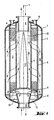
- Figure 1 shows the basic structure of the exemplary embodiment of the reactor according to the invention with its essential features.
- the representation is very schematic, in particular the relationships between the outer dimensions of the reactor and the material thicknesses do not correspond to the actual dimensions.
- the reactor is essentially cylindrical symmetrical about axis 1. It is delimited on the outside by a jacket 2, which has an upper 7 and a lower cap 8 with inlet 10 and outlet openings 9 for gas to be cleaned.
- the upper cap 7 is also broken through nozzle 11 for filling and suction of free-flowing material.
- annular adsorption bed 3 Arranged in the interior of the reactor is an annular adsorption bed 3, which is delimited by two cylinder-shell-shaped baskets, an outer 5 and an inner 4.
- the bed 3 is closed at the bottom by the bottom 6, which is rigidly attached to the lower calotte 8 of the jacket 2 via ribs 12 arranged in a star shape.
- the inner basket 4 is rigidly connected to the bottom 6 at its lower end. It is also supported by the ribs 12 arranged in a star shape on the lower cap 8 of the casing 2.
- the outer basket 5 stands on the lower cap 8, is welded to it and thus rigidly connected to the jacket 2.
- the baskets 4, 5 are made of perforated sheet metal for the most part.
- the holes are indicated in Figure 1 by horizontal lines (not to scale). Unperforated sheet metal is only used at the ends. Details of the structure of the baskets 4, 5 can be found in FIGS. 2 and 3 and the associated description text.
- the direction of flow of the gas to be purified is indicated in Figure 1 by arrows with solid lines (reaction or adsorption phase).
- the gas to be cleaned for example air, flows into the reactor via the inlet opening 10, is deflected through the underside of the base 6 and drip-off water is separated off in the process.
- the gas to be cleaned is then passed into the outer annular space 15 between the jacket 2 and the outer basket 5. From there, the gas to be cleaned flows with a radial component through the adsorption bed 3 into the inner annular space 16.
- this is also limited by a displacement body 17 constructed from truncated cones, which reduces the cross section of the inner annular space 16. This ensures an approximately uniform current density of the gas to be cleaned in bed 3, largely independently of the axial coordinate.
- a dust screen 13 is provided between the inner basket 4 and the displacement body 17 if necessary.
- a regeneration gas for example nitrogen, is conducted in the opposite direction during the regeneration phase (dashed arrows in FIG. 1).
- Figure 2 shows the detail A of Figure 1 in detail, on which the upper attachment of the outer basket 5 to the upper cap 7 of the shell 2 can be seen.
- the upper part of the outer basket 5 made of non-perforated sheet metal 18 is rigidly connected to the upper cap 7 by means of two annular weld seams 19.
- the inner basket 4 is welded to the upper cap 7 of the casing 2 in the same way.
- the attachment of the lower end of the outer basket 5 to the lower cap 8 is carried out analogously.
- the elongated holes 25 in the sheet metal 20 are regularly arranged in circles around the axis of symmetry 1. Their dimensions and their configuration are determined depending on the temperature gradient to be expected. In the present example, the hole width is 3 mm, the hole length is 30 mm and the web width (lateral distance between holes of two adjacent circles) is 6 mm (see FIG. 3). If the particle size of the bulk material is smaller than the hole width, both baskets 4, 5 have a wire mesh 22 on their side facing the interior of the bed 3, as shown in FIG. 3 with reference to the outer basket 5.
- the configuration of the perforated plate 20 defines the essential properties of the baskets for the invention. This is explained using the processing shown in FIG. 3.
- the horizontal in the drawing corresponds to a tangential direction around the axis of symmetry of the reactor, the vertical corresponds to the axial direction.
- the perforated plate has continuous webs in the tangential direction and therefore behaves along the direction of the webs similarly to an unperforated material. In this sense, the perforated plate 20 behaves rigidly in the tangential direction.
- the basket which essentially consists of a perforated plate in the form of a cylindrical jacket, is thus radially rigid.
- the perforated plate 20 In the axial direction, the perforated plate 20 has no webs that are continuous on a straight line, but is repeatedly interrupted by holes. It is therefore compressible and stretchable in this direction. Forces in the axial direction can be absorbed not only by the elasticity of the material, but also by changing the shape of the perforated plate 20, for example by distorting the shape of the holes 25.
- FIG. 4 shows a projection of a section of the cylindrical surface of a basket
- FIG. 5 shows a section along an axial line; the axis of symmetry of the reactor is vertical in the figures.
- Both basket types are perforated, generally stamped, sheet metal with a thickness d of 2 to 10, preferably 2.5 to 6.0 mm.
- the holes are elongated, with their longer side aligned along the horizontal (the horizontal in the drawings) and arranged in circles around the axis of symmetry of the reactor.
- a vertically continuous web (30a, 30b) that is not interrupted by holes is located between two adjacent circles.
- the baskets are therefore on the one hand along the circles (tangential) and thus radially rigid overall and on the other hand can accommodate axial changes in length by bending the holes (axially expandable in the sense of the invention).
- Basket type of figure 3 Length of holes a: 20 to 50 mm, preferably 25 to 35 mm Width of the holes b: 2 to 5 mm, preferably 2.5 to 3.5 mm horizontal web width c h : 4 to 8 mm, preferably 5.0 to 7.0 mm vertical web width c v : 5 to 20 mm, preferably 8.0 to 12.0 mm Basket type of Figures 4 and 5: Length of holes a: 10 to 40 mm, preferably 20 to 30 mm Width of the holes b: 0.8 to 2.0 mm, preferably 1.0 to 1.5 mm horizontal web width c h : 3.0 to 10 mm, preferably 4.0 to 6.0 mm vertical web width c v : 3.0 to 12 mm, preferably 5.0 to 7.0 mm
- the smaller dimensions of the holes in the second embodiment mean that an additional fine-mesh wire mesh on the inside of the basket (on the right in FIG. 5) can generally be dispensed with, since the adsorbent or catalyst particles are retained solely by the perforated sheet will.
- FIGS. 6 and 7 show in a similar view a third basket version with which the invention can be implemented. This is constructed completely differently, namely as wire mesh.
- Circular, horizontal wires 40a, 40b, 40c are interwoven with vertical (axial) wires 41a, 41b, 41c.
- the horizontal wires 40a, 40b, 40C do not have any significant bends and thus (similar to the continuous webs 30a, 30b of the previous example) bring about the radial rigidity of the basket.
- the vertical wires 41a, 41b, 41c are provided with bends, so-called joints, 42 at regular intervals of two mesh sizes. These can change their shape in the event of tensile or tensile stresses in the vertical (axial) direction and thus compensate for temperature-induced changes in length.
- the basket realized as a wire mesh is radially rigid and axially stretchable in the sense of the invention due to its special weave.
- the wire thickness is generally between 1.0 and 10 mm, preferably between 1.0 and 5.0 mm, most preferably between 2.0 and 3.0 mm.
Landscapes
- Chemical & Material Sciences (AREA)
- Physics & Mathematics (AREA)
- Fluid Mechanics (AREA)
- Organic Chemistry (AREA)
- Chemical Kinetics & Catalysis (AREA)
- Devices And Processes Conducted In The Presence Of Fluids And Solid Particles (AREA)
- Physical Or Chemical Processes And Apparatus (AREA)
- Treatment Of Water By Oxidation Or Reduction (AREA)
- Separation Of Gases By Adsorption (AREA)
- Organic Low-Molecular-Weight Compounds And Preparation Thereof (AREA)
Priority Applications (1)
| Application Number | Priority Date | Filing Date | Title |
|---|---|---|---|
| AT90110862T ATE82159T1 (de) | 1989-06-16 | 1990-06-08 | Reaktor. |
Applications Claiming Priority (2)
| Application Number | Priority Date | Filing Date | Title |
|---|---|---|---|
| DE3919750A DE3919750A1 (de) | 1989-06-16 | 1989-06-16 | Reaktor |
| DE3919750 | 1989-06-16 |
Publications (3)
| Publication Number | Publication Date |
|---|---|
| EP0402783A2 true EP0402783A2 (fr) | 1990-12-19 |
| EP0402783A3 EP0402783A3 (fr) | 1991-02-27 |
| EP0402783B1 EP0402783B1 (fr) | 1992-11-11 |
Family
ID=6382905
Family Applications (1)
| Application Number | Title | Priority Date | Filing Date |
|---|---|---|---|
| EP90110862A Expired - Lifetime EP0402783B1 (fr) | 1989-06-16 | 1990-06-08 | Réacteur |
Country Status (14)
| Country | Link |
|---|---|
| US (1) | US5827485A (fr) |
| EP (1) | EP0402783B1 (fr) |
| JP (1) | JP2965625B2 (fr) |
| AT (1) | ATE82159T1 (fr) |
| AU (1) | AU629359B2 (fr) |
| CA (1) | CA2028274C (fr) |
| CZ (1) | CZ285430B6 (fr) |
| DD (1) | DD301873A9 (fr) |
| DE (2) | DE3919750A1 (fr) |
| HU (1) | HU207241B (fr) |
| PL (1) | PL285646A1 (fr) |
| RU (1) | RU1809778C (fr) |
| UA (1) | UA11069A (fr) |
| ZA (1) | ZA904659B (fr) |
Cited By (15)
| Publication number | Priority date | Publication date | Assignee | Title |
|---|---|---|---|---|
| EP0526343A1 (fr) * | 1991-07-31 | 1993-02-03 | L'air Liquide S.A. | Adsorbeur à lits d'adsorbants annulaires superposés |
| EP0724906A1 (fr) * | 1995-02-01 | 1996-08-07 | Fina Technology, Inc. | Réacteur et procédé pour la déshydrogénation d'éthylbenzène en styrolène |
| US5759242A (en) * | 1996-07-23 | 1998-06-02 | Praxair Technology, Inc. | Radial bed vaccum/pressure swing adsorber vessel |
| EP0897746A1 (fr) * | 1997-08-14 | 1999-02-24 | Linde Aktiengesellschaft | Réacteur pour réactions chimiques, en particulier pour des procédés de séparation par adsorption |
| RU2154523C1 (ru) * | 1999-07-05 | 2000-08-20 | Воронежское открытое акционерное общество "Синтезкаучукпроект" | Реактор радиального типа для каталитического дегидрирования углеводородов |
| US6152992A (en) * | 1997-10-22 | 2000-11-28 | Linde Aktiengesellschaft | Reactor and process of using same |
| EP1892028A1 (fr) * | 2006-08-07 | 2008-02-27 | Delphi Technologies, Inc. | Module de tamis radial |
| WO2009003663A1 (fr) * | 2007-07-04 | 2009-01-08 | Ammonia Casale S.A. | Système de parois pour lits catalytiques de réacteurs de synthèse et procédé de production associé |
| RU2420343C1 (ru) * | 2009-11-27 | 2011-06-10 | Надежда Анатольевна Пивоварова | Газораспределительное устройство |
| EP2448653A4 (fr) * | 2009-06-29 | 2012-11-28 | Uop Llc | Récipient, système et procédé pour réduire la distribution de flux inégal |
| FR3028426A1 (fr) * | 2014-11-14 | 2016-05-20 | Ifp Energies Now | Conduit de collecte pour un reacteur radial comprenant des filets pleins. |
| DE102015002260A1 (de) | 2015-02-25 | 2016-08-25 | Linde Aktiengesellschaft | Verfahren zum Herstellen eines horizontal durchströmten Adsorbers und Trennwandmodul zur Verwendung in diesem Verfahren |
| FR3056119A1 (fr) * | 2016-09-20 | 2018-03-23 | Total Raffinage Chimie | Paroi cylindrique de filtrage de particules solides dans un fluide |
| EP3318321A1 (fr) | 2016-11-08 | 2018-05-09 | Linde Aktiengesellschaft | Procédé de fabrication d'un dispositif d'adsorption, procédé d'équipement pour un dispositif d'adsorption et dispositif d'adsorption |
| EP4052776A1 (fr) * | 2021-03-05 | 2022-09-07 | L'Air Liquide, société anonyme pour l'Étude et l'Exploitation des procédés Georges Claude | Adsorbeur radial à circulation radiale d'un gaz |
Families Citing this family (48)
| Publication number | Priority date | Publication date | Assignee | Title |
|---|---|---|---|---|
| US4938422A (en) * | 1987-12-23 | 1990-07-03 | Uop | Inlet distributor for downflow reactor |
| US5855775A (en) | 1995-05-05 | 1999-01-05 | Kerfoot; William B. | Microporous diffusion apparatus |
| USRE43350E1 (en) | 1995-05-05 | 2012-05-08 | Think Village-Kerfoot, Llc | Microporous diffusion apparatus |
| DE19540537C1 (de) * | 1995-10-31 | 1997-06-26 | Uhde Gmbh | Vorrichtung zur Beaufschlagung einer Festkörperschüttung |
| US6245303B1 (en) * | 1998-01-14 | 2001-06-12 | Arthur D. Little, Inc. | Reactor for producing hydrogen from hydrocarbon fuels |
| US5814129A (en) * | 1997-04-11 | 1998-09-29 | Air Products And Chemical, Inc. | Radial flow adsorption vessel |
| US6086659A (en) * | 1999-01-29 | 2000-07-11 | Air Products And Chemicals, Inc. | Radial flow adsorption vessel |
| US6447676B1 (en) * | 1999-12-22 | 2002-09-10 | William B. Kerfoot | Springbox for water remediation |
| US6436285B1 (en) * | 1999-12-22 | 2002-08-20 | William B. Kerfoot | Laminated microporous diffuser |
| US8557110B2 (en) | 2000-07-06 | 2013-10-15 | Thinkvillage-Kerfoot, Llc | Groundwater and subsurface remediation |
| US6582611B1 (en) | 2000-07-06 | 2003-06-24 | William B. Kerfoot | Groundwater and subsurface remediation |
| US6663839B2 (en) | 2001-02-26 | 2003-12-16 | Abb Lummus Global Inc. | Radial flow gas phase reactor and method for reducing the nitrogen oxide content of a gas |
| US20020132147A1 (en) * | 2001-03-16 | 2002-09-19 | Yong Gao | Chambered reactor for fuel processing |
| RU2188069C1 (ru) * | 2001-11-08 | 2002-08-27 | Открытое акционерное общество Научно-исследовательский институт "Ярсинтез" | Реактор для каталитического дегидрирования углеводородов |
| US7220341B2 (en) * | 2002-03-11 | 2007-05-22 | Exxonmobil Chemical Patents Inc. | Controlling solids flow in a gas-solids reactor |
| US7666316B2 (en) | 2004-07-20 | 2010-02-23 | Thinkvillage-Kerfoot, Llc | Permanganate-coated ozone for groundwater and soil treatment with in-situ oxidation |
| US8302939B2 (en) * | 2003-02-12 | 2012-11-06 | Thinkvillage-Kerfoot, Llc | Soil and water remediation system and method |
| US6913251B2 (en) | 2003-02-12 | 2005-07-05 | William B. Kerfoot | Deep well sparging |
| US7442313B2 (en) | 2003-08-27 | 2008-10-28 | Thinkvillage-Kerfoot, Llc | Environmental remediation method and system |
| RU2243028C1 (ru) * | 2003-04-29 | 2004-12-27 | Открытое акционерное общество Научно-исследовательский институт "Ярсинтез" | Реактор для каталитического дегидрирования углеводородов |
| US7401767B2 (en) | 2003-12-24 | 2008-07-22 | Kerfoot William B | Directional microporous diffuser and directional sparging |
| US7651611B2 (en) | 2006-07-12 | 2010-01-26 | Thinkvillage-Kerfoot, Llc | Directional microporous diffuser and directional sparging |
| US7569140B2 (en) | 2005-11-10 | 2009-08-04 | Thinkvillage-Kerfoot, Llc | Directional spargewell system |
| US8771507B2 (en) | 2003-12-24 | 2014-07-08 | Thinkvillage-Kerfoot, Llc | Directional microporous diffuser and directional sparging |
| US7621696B2 (en) | 2006-07-12 | 2009-11-24 | Thinkvillage-Kerfoot, Llc | Directional microporous diffuser and directional sparging |
| US20080107575A1 (en) * | 2004-12-08 | 2008-05-08 | Vetter Michael J | Apparatus and process for reacting fluid over catalyst bed |
| AU2005336050B2 (en) * | 2005-08-31 | 2011-01-06 | Coldway | Thermochemical reactor for a cooling and/or heating apparatus |
| EP1818094A1 (fr) * | 2006-02-13 | 2007-08-15 | Ammonia Casale S.A. | Systémes de murs pour des lits catalytiques dans des réacteurs de synthéses |
| US7695696B2 (en) * | 2006-07-19 | 2010-04-13 | Uop Llc | Screenless internals for radial flow reactors |
| RU2321453C2 (ru) * | 2006-08-07 | 2008-04-10 | Общество с ограниченной ответственностью Научно-производственная фирма "РИФИНГ" | Радиальный реактор для проведения каталитических процессов |
| RU2321452C2 (ru) * | 2006-08-07 | 2008-04-10 | Общество с ограниченной ответственностью Научно-производственная фирма "РИФИНГ" | Реактор радиальный для проведения каталитических процессов |
| US7749467B2 (en) * | 2007-12-18 | 2010-07-06 | Uop Llc | Optimizer hydraulic enhancement using milled plate |
| US7906081B2 (en) * | 2008-05-13 | 2011-03-15 | Uop Llc | Internal grids for adsorbent chambers and reactors |
| US7718146B2 (en) * | 2008-05-13 | 2010-05-18 | Uop Llc | Enhanced bed separation in a styrene monomer reactor using milled plates |
| US8101133B2 (en) | 2010-02-25 | 2012-01-24 | Praxair Technology, Inc. | Radial flow reactor |
| US8216343B2 (en) * | 2010-02-25 | 2012-07-10 | Praxair Technology, Inc. | Radial flow reactor with movable supports |
| US8257473B2 (en) * | 2010-07-08 | 2012-09-04 | Airsep Corporation | Sieve bed |
| US8313561B2 (en) | 2010-10-05 | 2012-11-20 | Praxair Technology, Inc. | Radial bed vessels having uniform flow distribution |
| GB201107073D0 (en) * | 2011-04-27 | 2011-06-08 | Davy Process Techn Ltd | Process |
| US9555346B2 (en) * | 2011-05-10 | 2017-01-31 | Cummins Filtration Ip Inc. | Filter with tri-flow path combinations |
| US9694401B2 (en) | 2013-03-04 | 2017-07-04 | Kerfoot Technologies, Inc. | Method and apparatus for treating perfluoroalkyl compounds |
| US9731241B2 (en) | 2014-06-12 | 2017-08-15 | Air Products And Chemicals, Inc. | Radial flow adsorber ‘U’ configuration |
| EP3037165A1 (fr) * | 2014-12-23 | 2016-06-29 | Casale SA | Procéde de réalisation de parois interieures d'un réacteur catalytique |
| RU169758U1 (ru) * | 2016-11-02 | 2017-03-31 | Общество с ограниченной ответственностью "ХАММЕЛЬ" | Реактор радиального типа для каталитического дегидрирования углеводородов |
| DE102017208319A1 (de) * | 2017-05-17 | 2018-11-22 | Thyssenkrupp Ag | Radialstromeinsatzvorrichtung zum Vorgeben wenigstens eines radialen Strömungspfades in einem Schüttungsreaktor sowie Montageverfahren und Verwendung |
| US10994238B2 (en) | 2018-09-07 | 2021-05-04 | Air Products And Chemicals, Inc. | Radial flow adsorption vessel comprising flexible screen |
| EP3646945A1 (fr) * | 2018-10-29 | 2020-05-06 | Casale Sa | Réacteur chimique radial ou axial-radial avec un catalyseur de particules fines |
| EP3901606A1 (fr) * | 2020-04-20 | 2021-10-27 | Catalytic Instruments GmbH & Co. KG | Thermodénudeur et procédé d'élimination de matière semi-volatile et de particules semi-volatiles dans un aérosol |
Family Cites Families (8)
| Publication number | Priority date | Publication date | Assignee | Title |
|---|---|---|---|---|
| US1429856A (en) * | 1921-01-07 | 1922-09-19 | Gen Electric | Adsorption apparatus for solvent recovery, etc. |
| GB546285A (en) * | 1940-11-30 | 1942-07-06 | Edgar Rouse Sutcliffe | Improvements relating to adsorption filters |
| US2517525A (en) * | 1947-10-13 | 1950-08-01 | Sun Oil Co | Catalytic reaction apparatus |
| US3620685A (en) * | 1969-07-30 | 1971-11-16 | Phillips Petroleum Co | Radial flow catalyst reactor |
| FR2541588B1 (fr) * | 1983-02-28 | 1985-07-05 | Air Liquide | Recipient et installation d'epuration par adsorption |
| GB8326856D0 (en) * | 1983-10-07 | 1983-11-09 | Shell Int Research | Moving catalyst bed reactor |
| GB2155349B (en) * | 1984-03-08 | 1988-03-02 | Shell Int Research | Movable catalyst bed reactor and process in which such a reactor is employed |
| US4673423A (en) * | 1985-07-23 | 1987-06-16 | Mack Trucks, Inc. | Split flow particulate filter |
-
1989
- 1989-06-16 DE DE3919750A patent/DE3919750A1/de not_active Withdrawn
-
1990
- 1990-06-08 EP EP90110862A patent/EP0402783B1/fr not_active Expired - Lifetime
- 1990-06-08 DE DE9090110862T patent/DE59000452D1/de not_active Expired - Lifetime
- 1990-06-08 AT AT90110862T patent/ATE82159T1/de not_active IP Right Cessation
- 1990-06-11 HU HU903795A patent/HU207241B/hu not_active IP Right Cessation
- 1990-06-14 AU AU57158/90A patent/AU629359B2/en not_active Ceased
- 1990-06-15 DD DD34172490A patent/DD301873A9/de unknown
- 1990-06-15 RU SU904830134A patent/RU1809778C/ru active
- 1990-06-15 JP JP2157398A patent/JP2965625B2/ja not_active Expired - Fee Related
- 1990-06-15 CZ CS903003A patent/CZ285430B6/cs not_active IP Right Cessation
- 1990-06-15 ZA ZA904659A patent/ZA904659B/xx unknown
- 1990-06-15 PL PL28564690A patent/PL285646A1/xx unknown
- 1990-06-15 UA UA4830134A patent/UA11069A/uk unknown
- 1990-06-18 CA CA002028274A patent/CA2028274C/fr not_active Expired - Fee Related
- 1990-06-18 US US07/539,831 patent/US5827485A/en not_active Expired - Fee Related
Cited By (28)
| Publication number | Priority date | Publication date | Assignee | Title |
|---|---|---|---|---|
| EP0526343A1 (fr) * | 1991-07-31 | 1993-02-03 | L'air Liquide S.A. | Adsorbeur à lits d'adsorbants annulaires superposés |
| FR2679787A1 (fr) * | 1991-07-31 | 1993-02-05 | Air Liquide | Adsorbeur a lits d'adsorbants annulaires superposes. |
| US5232479A (en) * | 1991-07-31 | 1993-08-03 | L'air Liquide, Societe Anonyme Pour L'etude Et L'exploitation Des Procedes Georges Claude | Adsorber comprising annular superposed beds of adsorbent materials |
| EP0726087A1 (fr) * | 1991-07-31 | 1996-08-14 | L'air Liquide, Societe Anonyme Pour L'etude Et L'exploitation Des Procedes Georges Claude | Adsorbeur à lits d'adsorbants annulaires superposés |
| EP0724906A1 (fr) * | 1995-02-01 | 1996-08-07 | Fina Technology, Inc. | Réacteur et procédé pour la déshydrogénation d'éthylbenzène en styrolène |
| US5759242A (en) * | 1996-07-23 | 1998-06-02 | Praxair Technology, Inc. | Radial bed vaccum/pressure swing adsorber vessel |
| EP0897746A1 (fr) * | 1997-08-14 | 1999-02-24 | Linde Aktiengesellschaft | Réacteur pour réactions chimiques, en particulier pour des procédés de séparation par adsorption |
| US6152992A (en) * | 1997-10-22 | 2000-11-28 | Linde Aktiengesellschaft | Reactor and process of using same |
| RU2154523C1 (ru) * | 1999-07-05 | 2000-08-20 | Воронежское открытое акционерное общество "Синтезкаучукпроект" | Реактор радиального типа для каталитического дегидрирования углеводородов |
| EP1892028A1 (fr) * | 2006-08-07 | 2008-02-27 | Delphi Technologies, Inc. | Module de tamis radial |
| WO2009003663A1 (fr) * | 2007-07-04 | 2009-01-08 | Ammonia Casale S.A. | Système de parois pour lits catalytiques de réacteurs de synthèse et procédé de production associé |
| EP2014356A1 (fr) * | 2007-07-04 | 2009-01-14 | Ammonia Casale S.A. | Système de parois de lits catalytiques pour réacteurs de synthèse et procédé de production du système |
| US9138712B2 (en) | 2007-07-04 | 2015-09-22 | Casale Sa | Wall system for catalytic beds of synthesis reactors and relative production process |
| AU2008271605B2 (en) * | 2007-07-04 | 2011-07-28 | Ammonia Casale S.A. | Wall system for catalytic beds of synthesis reactors and relative production process |
| US8435458B2 (en) | 2007-07-04 | 2013-05-07 | Ammonia Casale S.A. | Wall system for catalytic beds of synthesis reactors and relative production process |
| EP2448653A4 (fr) * | 2009-06-29 | 2012-11-28 | Uop Llc | Récipient, système et procédé pour réduire la distribution de flux inégal |
| RU2420343C1 (ru) * | 2009-11-27 | 2011-06-10 | Надежда Анатольевна Пивоварова | Газораспределительное устройство |
| FR3028426A1 (fr) * | 2014-11-14 | 2016-05-20 | Ifp Energies Now | Conduit de collecte pour un reacteur radial comprenant des filets pleins. |
| DE102015002260A1 (de) | 2015-02-25 | 2016-08-25 | Linde Aktiengesellschaft | Verfahren zum Herstellen eines horizontal durchströmten Adsorbers und Trennwandmodul zur Verwendung in diesem Verfahren |
| EP3061514A1 (fr) | 2015-02-25 | 2016-08-31 | Linde Aktiengesellschaft | Procédé de production d'un absorbeur traversé horizontalement et module de paroi de séparation destiné à être utilisé dans ledit procédé |
| WO2016134816A1 (fr) | 2015-02-25 | 2016-09-01 | Linde Aktiengesellschaft | Procédé pour la fabrication d'un adsorbant à écoulement horizontal et module de paroi de séparation destiné à être utilisé dans ce procédé |
| FR3056119A1 (fr) * | 2016-09-20 | 2018-03-23 | Total Raffinage Chimie | Paroi cylindrique de filtrage de particules solides dans un fluide |
| WO2018054838A1 (fr) * | 2016-09-20 | 2018-03-29 | Total Raffinage Chimie | Paroi cylindrique de filtrage de particules solides dans un fluide |
| CN109963644A (zh) * | 2016-09-20 | 2019-07-02 | 道达尔炼油化学公司 | 用于过滤流体中的固体颗粒的圆筒形壁 |
| EP3318321A1 (fr) | 2016-11-08 | 2018-05-09 | Linde Aktiengesellschaft | Procédé de fabrication d'un dispositif d'adsorption, procédé d'équipement pour un dispositif d'adsorption et dispositif d'adsorption |
| EP4052776A1 (fr) * | 2021-03-05 | 2022-09-07 | L'Air Liquide, société anonyme pour l'Étude et l'Exploitation des procédés Georges Claude | Adsorbeur radial à circulation radiale d'un gaz |
| FR3120316A1 (fr) * | 2021-03-05 | 2022-09-09 | L'air Liquide Societe Anonyme Pour L'etude Et L'exploitation Des Procedes Georges Claude | Adsorbeur radial à circulation radiale d'un gaz |
| US11896927B2 (en) | 2021-03-05 | 2024-02-13 | L'air Liquide Societe Anonyme Pour L'etude Et L'exploitation Des Procedes Georges Claude | Radial adsorber with radial circulation of gas |
Also Published As
| Publication number | Publication date |
|---|---|
| EP0402783B1 (fr) | 1992-11-11 |
| ATE82159T1 (de) | 1992-11-15 |
| DE59000452D1 (de) | 1992-12-17 |
| RU1809778C (ru) | 1993-04-15 |
| AU5715890A (en) | 1990-12-20 |
| HU207241B (en) | 1993-03-29 |
| EP0402783A3 (fr) | 1991-02-27 |
| ZA904659B (en) | 1991-04-24 |
| AU629359B2 (en) | 1992-10-01 |
| CA2028274C (fr) | 2001-12-25 |
| CA2028274A1 (fr) | 1990-12-17 |
| CZ285430B6 (cs) | 1999-08-11 |
| DD301873A9 (de) | 1994-06-09 |
| CZ300390A3 (cs) | 1999-05-12 |
| JPH03131337A (ja) | 1991-06-04 |
| HUT57999A (en) | 1992-01-28 |
| DE3919750A1 (de) | 1990-12-20 |
| UA11069A (uk) | 1996-12-25 |
| PL285646A1 (en) | 1991-01-28 |
| JP2965625B2 (ja) | 1999-10-18 |
| HU903795D0 (en) | 1990-11-28 |
| US5827485A (en) | 1998-10-27 |
Similar Documents
| Publication | Publication Date | Title |
|---|---|---|
| EP0402783B1 (fr) | Réacteur | |
| DE60010135T2 (de) | Adsorptionsreaktor mit radialer Strömung | |
| DE60129686T2 (de) | Reaktor für exothermische oder endothermische heterogene reaktionen | |
| EP2640504B1 (fr) | Réacteur chimique comprenant une matière à mailles en fil tricoté comme dispositif de retenue pour particules | |
| DE69007522T2 (de) | Brennstabbündelfussstück mit Teilchenfangvorrichtung und Brennstabbündel mit einem solchen Fussstück. | |
| DE2848086C2 (de) | Röhrenreaktor für katalytische Prozesse | |
| DE1544027A1 (de) | Gitter fuer Einrichtungen,in denen Daempfe und Fluessigkeiten miteinander in Beruehrung gebracht werden | |
| EP0517728B1 (fr) | Structure d'element combustible de reacteur nucleaire avec un tube pour caloporteur ayant une fonction de support. | |
| EP0054827A1 (fr) | Elément combustible pour réacteurs nucléaires à eau bouillante | |
| DE1945453B2 (de) | Filterpatrone | |
| DE69905406T2 (de) | Katalysatorträger | |
| DE69502611T2 (de) | Reaktor für exothermische, heterogene katalytische synthesereaktionen | |
| DE2653905B2 (de) | Wärmeübertrager mit einem Bündel schraubenlinienförmig gewundener Rohre | |
| DE19746698C2 (de) | Reaktor | |
| EP0812802A2 (fr) | Réacteur de reformage, spécialement pour le reformage à la vapeur de méthanol | |
| DE69410215T2 (de) | Vorrichtung für schwingungsneutralisierendes Festsetzen von Wärmetauscherrohren und seine Verwendung | |
| WO2005009608A1 (fr) | Reacteur pour oxydations partielles, equipe de modules formes de plaques de tole thermiques | |
| DE69104925T2 (de) | Vorrichtung für schwingungsneutralisierendes Festsetzen von Wärmetauscherrohren. | |
| DE69509172T2 (de) | Kernreaktorbrennstabbündel mit als unterer Befestigungsplatte ausgeführter Filter | |
| DE3825724C2 (de) | Behälter | |
| DE4101918A1 (de) | Verbrennungsanlage | |
| DE202004017428U1 (de) | Gasgenerator und Gassackmodul | |
| DE2402169A1 (de) | Gittersystem fuer den auslass eines katalysatorbeschickten reaktors | |
| EP2753576B1 (fr) | Dispositif pour réduire le phénomène de by-pass dans des brûleurs d'oxydation d'ammoniac | |
| DE2936148A1 (de) | Stuetzgitter fuer waermeuebertrager und verfahren zu seiner herstellung |
Legal Events
| Date | Code | Title | Description |
|---|---|---|---|
| PUAI | Public reference made under article 153(3) epc to a published international application that has entered the european phase |
Free format text: ORIGINAL CODE: 0009012 |
|
| AK | Designated contracting states |
Kind code of ref document: A2 Designated state(s): AT BE DE ES FR GB IT NL SE |
|
| PUAL | Search report despatched |
Free format text: ORIGINAL CODE: 0009013 |
|
| AK | Designated contracting states |
Kind code of ref document: A3 Designated state(s): AT BE DE ES FR GB IT NL SE |
|
| 17P | Request for examination filed |
Effective date: 19910608 |
|
| 17Q | First examination report despatched |
Effective date: 19911007 |
|
| GRAA | (expected) grant |
Free format text: ORIGINAL CODE: 0009210 |
|
| AK | Designated contracting states |
Kind code of ref document: B1 Designated state(s): AT BE DE ES FR GB IT NL SE |
|
| PG25 | Lapsed in a contracting state [announced via postgrant information from national office to epo] |
Ref country code: IT Free format text: LAPSE BECAUSE OF FAILURE TO SUBMIT A TRANSLATION OF THE DESCRIPTION OR TO PAY THE FEE WITHIN THE PRESCRIBED TIME-LIMIT;WARNING: LAPSES OF ITALIAN PATENTS WITH EFFECTIVE DATE BEFORE 2007 MAY HAVE OCCURRED AT ANY TIME BEFORE 2007. THE CORRECT EFFECTIVE DATE MAY BE DIFFERENT FROM THE ONE RECORDED. Effective date: 19921111 Ref country code: ES Free format text: THE PATENT HAS BEEN ANNULLED BY A DECISION OF A NATIONAL AUTHORITY Effective date: 19921111 Ref country code: BE Effective date: 19921111 Ref country code: SE Effective date: 19921111 |
|
| REF | Corresponds to: |
Ref document number: 82159 Country of ref document: AT Date of ref document: 19921115 Kind code of ref document: T |
|
| GBT | Gb: translation of ep patent filed (gb section 77(6)(a)/1977) | ||
| REF | Corresponds to: |
Ref document number: 59000452 Country of ref document: DE Date of ref document: 19921217 |
|
| ET | Fr: translation filed | ||
| PG25 | Lapsed in a contracting state [announced via postgrant information from national office to epo] |
Ref country code: AT Effective date: 19930608 |
|
| PLBE | No opposition filed within time limit |
Free format text: ORIGINAL CODE: 0009261 |
|
| STAA | Information on the status of an ep patent application or granted ep patent |
Free format text: STATUS: NO OPPOSITION FILED WITHIN TIME LIMIT |
|
| 26N | No opposition filed | ||
| REG | Reference to a national code |
Ref country code: GB Ref legal event code: IF02 |
|
| PGFP | Annual fee paid to national office [announced via postgrant information from national office to epo] |
Ref country code: GB Payment date: 20030604 Year of fee payment: 14 |
|
| PGFP | Annual fee paid to national office [announced via postgrant information from national office to epo] |
Ref country code: FR Payment date: 20030610 Year of fee payment: 14 |
|
| PGFP | Annual fee paid to national office [announced via postgrant information from national office to epo] |
Ref country code: NL Payment date: 20040603 Year of fee payment: 15 |
|
| PG25 | Lapsed in a contracting state [announced via postgrant information from national office to epo] |
Ref country code: GB Free format text: LAPSE BECAUSE OF NON-PAYMENT OF DUE FEES Effective date: 20040608 |
|
| GBPC | Gb: european patent ceased through non-payment of renewal fee |
Effective date: 20040608 |
|
| PG25 | Lapsed in a contracting state [announced via postgrant information from national office to epo] |
Ref country code: FR Free format text: LAPSE BECAUSE OF NON-PAYMENT OF DUE FEES Effective date: 20050228 |
|
| REG | Reference to a national code |
Ref country code: FR Ref legal event code: ST |
|
| PG25 | Lapsed in a contracting state [announced via postgrant information from national office to epo] |
Ref country code: NL Free format text: LAPSE BECAUSE OF NON-PAYMENT OF DUE FEES Effective date: 20060101 |
|
| NLV4 | Nl: lapsed or anulled due to non-payment of the annual fee |
Effective date: 20060101 |
|
| PGFP | Annual fee paid to national office [announced via postgrant information from national office to epo] |
Ref country code: DE Payment date: 20090604 Year of fee payment: 20 |
|
| PG25 | Lapsed in a contracting state [announced via postgrant information from national office to epo] |
Ref country code: DE Free format text: LAPSE BECAUSE OF EXPIRATION OF PROTECTION Effective date: 20100608 |