EP0812802A2 - Réacteur de reformage, spécialement pour le reformage à la vapeur de méthanol - Google Patents
Réacteur de reformage, spécialement pour le reformage à la vapeur de méthanol Download PDFInfo
- Publication number
- EP0812802A2 EP0812802A2 EP97107906A EP97107906A EP0812802A2 EP 0812802 A2 EP0812802 A2 EP 0812802A2 EP 97107906 A EP97107906 A EP 97107906A EP 97107906 A EP97107906 A EP 97107906A EP 0812802 A2 EP0812802 A2 EP 0812802A2
- Authority
- EP
- European Patent Office
- Prior art keywords
- reaction chamber
- catalyst
- gas
- reaction
- reactor
- Prior art date
- Legal status (The legal status is an assumption and is not a legal conclusion. Google has not performed a legal analysis and makes no representation as to the accuracy of the status listed.)
- Granted
Links
Images

Classifications
-
- H—ELECTRICITY
- H01—ELECTRIC ELEMENTS
- H01M—PROCESSES OR MEANS, e.g. BATTERIES, FOR THE DIRECT CONVERSION OF CHEMICAL ENERGY INTO ELECTRICAL ENERGY
- H01M8/00—Fuel cells; Manufacture thereof
- H01M8/06—Combination of fuel cells with means for production of reactants or for treatment of residues
- H01M8/0606—Combination of fuel cells with means for production of reactants or for treatment of residues with means for production of gaseous reactants
- H01M8/0612—Combination of fuel cells with means for production of reactants or for treatment of residues with means for production of gaseous reactants from carbon-containing material
- H01M8/0625—Combination of fuel cells with means for production of reactants or for treatment of residues with means for production of gaseous reactants from carbon-containing material in a modular combined reactor/fuel cell structure
- H01M8/0631—Reactor construction specially adapted for combination reactor/fuel cell
-
- B—PERFORMING OPERATIONS; TRANSPORTING
- B01—PHYSICAL OR CHEMICAL PROCESSES OR APPARATUS IN GENERAL
- B01J—CHEMICAL OR PHYSICAL PROCESSES, e.g. CATALYSIS OR COLLOID CHEMISTRY; THEIR RELEVANT APPARATUS
- B01J8/00—Chemical or physical processes in general, conducted in the presence of fluids and solid particles; Apparatus for such processes
- B01J8/0015—Feeding of the particles in the reactor; Evacuation of the particles out of the reactor
- B01J8/002—Feeding of the particles in the reactor; Evacuation of the particles out of the reactor with a moving instrument
-
- B—PERFORMING OPERATIONS; TRANSPORTING
- B01—PHYSICAL OR CHEMICAL PROCESSES OR APPARATUS IN GENERAL
- B01J—CHEMICAL OR PHYSICAL PROCESSES, e.g. CATALYSIS OR COLLOID CHEMISTRY; THEIR RELEVANT APPARATUS
- B01J8/00—Chemical or physical processes in general, conducted in the presence of fluids and solid particles; Apparatus for such processes
- B01J8/008—Details of the reactor or of the particulate material; Processes to increase or to retard the rate of reaction
-
- B—PERFORMING OPERATIONS; TRANSPORTING
- B01—PHYSICAL OR CHEMICAL PROCESSES OR APPARATUS IN GENERAL
- B01J—CHEMICAL OR PHYSICAL PROCESSES, e.g. CATALYSIS OR COLLOID CHEMISTRY; THEIR RELEVANT APPARATUS
- B01J8/00—Chemical or physical processes in general, conducted in the presence of fluids and solid particles; Apparatus for such processes
- B01J8/02—Chemical or physical processes in general, conducted in the presence of fluids and solid particles; Apparatus for such processes with stationary particles, e.g. in fixed beds
- B01J8/06—Chemical or physical processes in general, conducted in the presence of fluids and solid particles; Apparatus for such processes with stationary particles, e.g. in fixed beds in tube reactors; the solid particles being arranged in tubes
-
- C—CHEMISTRY; METALLURGY
- C01—INORGANIC CHEMISTRY
- C01B—NON-METALLIC ELEMENTS; COMPOUNDS THEREOF; METALLOIDS OR COMPOUNDS THEREOF NOT COVERED BY SUBCLASS C01C
- C01B3/00—Hydrogen; Gaseous mixtures containing hydrogen; Separation of hydrogen from mixtures containing it; Purification of hydrogen; Reversible storage of hydrogen
- C01B3/02—Production of hydrogen; Production of gaseous mixtures containing hydrogen
- C01B3/32—Production of hydrogen; Production of gaseous mixtures containing hydrogen by reaction of gaseous or liquid organic compounds with gasifying agents, e.g. water, carbon dioxide or air
- C01B3/323—Catalytic reaction of gaseous or liquid organic compounds other than hydrocarbons with gasifying agents
-
- C—CHEMISTRY; METALLURGY
- C01—INORGANIC CHEMISTRY
- C01B—NON-METALLIC ELEMENTS; COMPOUNDS THEREOF; METALLOIDS OR COMPOUNDS THEREOF NOT COVERED BY SUBCLASS C01C
- C01B3/00—Hydrogen; Gaseous mixtures containing hydrogen; Separation of hydrogen from mixtures containing it; Purification of hydrogen; Reversible storage of hydrogen
- C01B3/02—Production of hydrogen; Production of gaseous mixtures containing hydrogen
- C01B3/32—Production of hydrogen; Production of gaseous mixtures containing hydrogen by reaction of gaseous or liquid organic compounds with gasifying agents, e.g. water, carbon dioxide or air
- C01B3/34—Production of hydrogen; Production of gaseous mixtures containing hydrogen by reaction of gaseous or liquid organic compounds with gasifying agents, e.g. water, carbon dioxide or air by reaction of hydrocarbons with gasifying agents
- C01B3/38—Production of hydrogen; Production of gaseous mixtures containing hydrogen by reaction of gaseous or liquid organic compounds with gasifying agents, e.g. water, carbon dioxide or air by reaction of hydrocarbons with gasifying agents using catalysts
-
- B—PERFORMING OPERATIONS; TRANSPORTING
- B01—PHYSICAL OR CHEMICAL PROCESSES OR APPARATUS IN GENERAL
- B01J—CHEMICAL OR PHYSICAL PROCESSES, e.g. CATALYSIS OR COLLOID CHEMISTRY; THEIR RELEVANT APPARATUS
- B01J2208/00—Processes carried out in the presence of solid particles; Reactors therefor
- B01J2208/00008—Controlling the process
- B01J2208/00017—Controlling the temperature
- B01J2208/00106—Controlling the temperature by indirect heat exchange
- B01J2208/00115—Controlling the temperature by indirect heat exchange with heat exchange elements inside the bed of solid particles
- B01J2208/00132—Tubes
-
- B—PERFORMING OPERATIONS; TRANSPORTING
- B01—PHYSICAL OR CHEMICAL PROCESSES OR APPARATUS IN GENERAL
- B01J—CHEMICAL OR PHYSICAL PROCESSES, e.g. CATALYSIS OR COLLOID CHEMISTRY; THEIR RELEVANT APPARATUS
- B01J2208/00—Processes carried out in the presence of solid particles; Reactors therefor
- B01J2208/00008—Controlling the process
- B01J2208/00654—Controlling the process by measures relating to the particulate material
- B01J2208/0069—Attrition
-
- B—PERFORMING OPERATIONS; TRANSPORTING
- B01—PHYSICAL OR CHEMICAL PROCESSES OR APPARATUS IN GENERAL
- B01J—CHEMICAL OR PHYSICAL PROCESSES, e.g. CATALYSIS OR COLLOID CHEMISTRY; THEIR RELEVANT APPARATUS
- B01J2208/00—Processes carried out in the presence of solid particles; Reactors therefor
- B01J2208/00796—Details of the reactor or of the particulate material
- B01J2208/00884—Means for supporting the bed of particles, e.g. grids, bars, perforated plates
-
- C—CHEMISTRY; METALLURGY
- C01—INORGANIC CHEMISTRY
- C01B—NON-METALLIC ELEMENTS; COMPOUNDS THEREOF; METALLOIDS OR COMPOUNDS THEREOF NOT COVERED BY SUBCLASS C01C
- C01B2203/00—Integrated processes for the production of hydrogen or synthesis gas
- C01B2203/02—Processes for making hydrogen or synthesis gas
- C01B2203/0205—Processes for making hydrogen or synthesis gas containing a reforming step
- C01B2203/0227—Processes for making hydrogen or synthesis gas containing a reforming step containing a catalytic reforming step
- C01B2203/0233—Processes for making hydrogen or synthesis gas containing a reforming step containing a catalytic reforming step the reforming step being a steam reforming step
-
- C—CHEMISTRY; METALLURGY
- C01—INORGANIC CHEMISTRY
- C01B—NON-METALLIC ELEMENTS; COMPOUNDS THEREOF; METALLOIDS OR COMPOUNDS THEREOF NOT COVERED BY SUBCLASS C01C
- C01B2203/00—Integrated processes for the production of hydrogen or synthesis gas
- C01B2203/06—Integration with other chemical processes
- C01B2203/066—Integration with other chemical processes with fuel cells
-
- C—CHEMISTRY; METALLURGY
- C01—INORGANIC CHEMISTRY
- C01B—NON-METALLIC ELEMENTS; COMPOUNDS THEREOF; METALLOIDS OR COMPOUNDS THEREOF NOT COVERED BY SUBCLASS C01C
- C01B2203/00—Integrated processes for the production of hydrogen or synthesis gas
- C01B2203/08—Methods of heating or cooling
- C01B2203/0805—Methods of heating the process for making hydrogen or synthesis gas
- C01B2203/0833—Heating by indirect heat exchange with hot fluids, other than combustion gases, product gases or non-combustive exothermic reaction product gases
-
- C—CHEMISTRY; METALLURGY
- C01—INORGANIC CHEMISTRY
- C01B—NON-METALLIC ELEMENTS; COMPOUNDS THEREOF; METALLOIDS OR COMPOUNDS THEREOF NOT COVERED BY SUBCLASS C01C
- C01B2203/00—Integrated processes for the production of hydrogen or synthesis gas
- C01B2203/10—Catalysts for performing the hydrogen forming reactions
- C01B2203/1005—Arrangement or shape of catalyst
- C01B2203/1011—Packed bed of catalytic structures, e.g. particles, packing elements
-
- C—CHEMISTRY; METALLURGY
- C01—INORGANIC CHEMISTRY
- C01B—NON-METALLIC ELEMENTS; COMPOUNDS THEREOF; METALLOIDS OR COMPOUNDS THEREOF NOT COVERED BY SUBCLASS C01C
- C01B2203/00—Integrated processes for the production of hydrogen or synthesis gas
- C01B2203/10—Catalysts for performing the hydrogen forming reactions
- C01B2203/1041—Composition of the catalyst
- C01B2203/1076—Copper or zinc-based catalysts
-
- C—CHEMISTRY; METALLURGY
- C01—INORGANIC CHEMISTRY
- C01B—NON-METALLIC ELEMENTS; COMPOUNDS THEREOF; METALLOIDS OR COMPOUNDS THEREOF NOT COVERED BY SUBCLASS C01C
- C01B2203/00—Integrated processes for the production of hydrogen or synthesis gas
- C01B2203/10—Catalysts for performing the hydrogen forming reactions
- C01B2203/1041—Composition of the catalyst
- C01B2203/1082—Composition of support materials
-
- C—CHEMISTRY; METALLURGY
- C01—INORGANIC CHEMISTRY
- C01B—NON-METALLIC ELEMENTS; COMPOUNDS THEREOF; METALLOIDS OR COMPOUNDS THEREOF NOT COVERED BY SUBCLASS C01C
- C01B2203/00—Integrated processes for the production of hydrogen or synthesis gas
- C01B2203/12—Feeding the process for making hydrogen or synthesis gas
- C01B2203/1205—Composition of the feed
- C01B2203/1211—Organic compounds or organic mixtures used in the process for making hydrogen or synthesis gas
- C01B2203/1217—Alcohols
- C01B2203/1223—Methanol
-
- Y—GENERAL TAGGING OF NEW TECHNOLOGICAL DEVELOPMENTS; GENERAL TAGGING OF CROSS-SECTIONAL TECHNOLOGIES SPANNING OVER SEVERAL SECTIONS OF THE IPC; TECHNICAL SUBJECTS COVERED BY FORMER USPC CROSS-REFERENCE ART COLLECTIONS [XRACs] AND DIGESTS
- Y02—TECHNOLOGIES OR APPLICATIONS FOR MITIGATION OR ADAPTATION AGAINST CLIMATE CHANGE
- Y02E—REDUCTION OF GREENHOUSE GAS [GHG] EMISSIONS, RELATED TO ENERGY GENERATION, TRANSMISSION OR DISTRIBUTION
- Y02E60/00—Enabling technologies; Technologies with a potential or indirect contribution to GHG emissions mitigation
- Y02E60/30—Hydrogen technology
- Y02E60/50—Fuel cells
Definitions
- the invention relates to a reforming reactor according to the preamble of claim 1.
- Reforming reactors with a catalyst pellet bed introduced into the reaction chamber are known in many different designs and are used, for example, to obtain hydrogen, which e.g. can be used as fuel for a fuel cell arrangement. Reforming reactors of this type are e.g. in the published documents DE 44 23 587 A1 and DE 44 20 752 A1.
- vibrations occur which, when the catalyst pellet bed is freely movable in the reaction space, can lead to increased abrasion of the pellets. This abrasion is undesirable since it can lead to blockages or other impairments of downstream components.
- corresponding changes in the position of the catalyst material occur in the event of a loose pellet bed in the reforming reactor in the event of changes in the vehicle position. This can occur in extreme situations, e.g. with steep gradients, disadvantageous effect on the gas distribution and thus on the performance of the reactor.
- Such replacement or replenishment of catalyst material may be necessary from time to time, particularly in reforming reactors for generating hydrogen in mobile applications. It is especially in applications in vehicles for the installation of the reforming reactor, e.g. for hydrogen generation for a fuel cell system, a compact arrangement of the gas generation components is desirable. Because of the limited, narrow space available in the vehicle, it is disadvantageous if the reaction chamber cover of the reactor as a whole has to be removed in order to refill the catalyst material. In addition, there is a risk that, during this temporary complete removal of the cover, the catalyst material will come into contact with atmospheric oxygen over a large area, which often leads to damage to the active catalyst material.
- the invention is based on the technical problem of providing a reforming reactor of the type mentioned at the outset, which is suitable for mobile applications, e.g. for obtaining hydrogen for a fuel cell system of a motor vehicle, is particularly suitable and in particular allows a comparatively simple and problem-free refilling of catalyst material into the reaction space.
- the invention solves this problem by providing a reforming reactor with the features of claim 1 this reforming reactor, on the one hand, places the catalyst pellet bed under a position-fixing pressure, which largely suppresses signs of abrasion of the catalyst pellets, which can occur in a loose pellet bed due to the agitation of freely moving pellets and especially when used in motor vehicles by vehicle vibrations.
- This in turn prevents an increased pressure drop across the reforming reactor due to such blockages and thus a deterioration in the reforming properties.
- the reforming reactor has a filling device with which catalyst material can be filled into the reaction space from the outside through a passage opening which is introduced into one of the reaction space walls delimiting the reaction space.
- This filling opening means that no total reaction chamber wall needs to be removed for refilling or exchanging catalyst material, so that there is no risk that the active catalyst material located in the reaction chamber on the entire surface opposite the relevant reaction chamber wall with the outside atmosphere, e.g. with damaging atmospheric oxygen. Rather, such contact is limited to at most the area of the passage opening of the filling device. This area can be kept significantly smaller than that of an entire reaction chamber wall.
- the filling device includes a filling tube which opens at one end into the passage opening of the associated reaction chamber wall and in the other end of which catalyst material can be filled in from the outside.
- the filling tube can be closed securely against the passage of catalyst material by means of a sealing plunger, and depending on the application it can be provided that the sealing plunger is gas-permeable.
- the passage opening is provided for introducing catalyst material into the reaction space in the movable reaction space wall, which is also perforated in a gas-permeable manner.
- the catalyst material is refilled through a filling tube, which is fixed at one end to the movable reaction chamber wall and can thus simultaneously serve as an actuating element for moving this reaction chamber wall back against the pressing pressure.
- the tube extends through a gas inlet or gas outlet space which adjoins the movable reaction space wall on the side opposite the reaction space and opens into a filler neck which can be covered from the outside by a releasable closure.
- the filling tube can sit gas-tight in the filler neck, or if the gas is not gas-tight, gas can get from the gas inlet space into the filler neck and from there through the filler tube and the gas-permeable sealing plunger into the reaction space.
- gas can get from the gas inlet space into the filler neck and from there through the filler tube and the gas-permeable sealing plunger into the reaction space.
- a reforming reactor further developed according to claim 5 has an outlet device arranged in the lower region of the reaction chamber, with which catalyst material can be discharged from the reaction chamber. So it is also for a partial or complete removal of catalyst material from the Reaction space not required, a reaction space wall or. Remove the reaction chamber cover completely.
- the reforming reactor partially shown in FIG. 1 with its upper part can be used, for example, for water vapor reforming of methanol in a motor vehicle in order to obtain hydrogen therefrom as fuel for a fuel cell arrangement provided in the vehicle.
- the reforming reaction takes place in a reaction space 1 which is filled with a catalyst pellet bed 2, which is only idealized schematically in FIG. 1.
- the choice of catalyst material depends on the reforming reaction to be carried out.
- a Cu / ZnO / Al 2 O 3 material for example, is suitable for steam reforming of methanol.
- the reaction space 1 contains tubular reaction channels 1 a, which adjoin temperature fluid channels 3, through which a temperature fluid can be passed in order to keep the reaction space 1 at a temperature required for carrying out the reforming reaction.
- the temperature control fluid channels 3 end on the upper side in front of an upper, inlet-side reaction space region 1b, the volume of which is completely filled with the catalyst pellet bed 2 and into which the tubular reaction space channels 1a open.
- the reaction chamber 1 is on its top by an axially movable reaction chamber wall in the form of a perforated pressure plate 4, e.g. from a sheet metal material, delimited by an overlying gas antechamber 5, into which a connection opening 6 opens.
- the connection opening 6 leads from the gas antechamber 5 through a reactor housing 8 to the outside, which surrounds the gas antechamber 5 and the reaction chamber 1.
- the gas antechamber 5 forms a gas inlet space into which the gas mixture to be reacted is supplied via the connection opening 6, which in this case acts as an inlet opening, and is introduced into the reaction space 1 via the perforated pressure plate 4.
- the gas antechamber 5 can function as a gas outlet space, in which the reformate gas formed in the reaction space 1 collects, from where it is drawn off via the connection opening 6 which then acts as an outlet opening.
- the pressing pressure on the catalyst pellet bed 2 prevents any whirling up of individual pellets by the gas flow which is passed through the reaction space 1. Since the pressing pressure on the catalyst pellet bed 2 keeps the catalyst pellets largely immobile in their respective position and in this way prevents greater abrasion of the pellets, blockages caused by fine pellet abrasion dust within the catalyst pellet bed 2 itself and in subsequent units, such as For example, a downstream filter, not shown, avoided, which would otherwise lead to an increased pressure drop across the reforming reactor, which in turn would result in a deterioration in the reforming properties.
- the pressure can be suitably adjusted depending on the application by a suitable choice of the type and number of coil springs 7.
- the coil springs 7 are preferably positioned evenly distributed over the surface of the movable sheet metal plate 4 in order to exert a uniform pressing pressure on the catalyst pellet bed 2. Since the springs 7 are arranged in the gas antechamber 5 and are consequently in contact with the possibly reactive and / or hot gases there, they are preferably designed to be rustproof and resistant to high temperatures. Of course, other conventional means for generating the necessary compressive force on the movable sheet metal plate 4 in the direction of the reaction chamber 1 can be used instead of the springs 7.
- the reforming reactor also contains a filling device, via which catalyst pellet material can be introduced into reaction chamber 1 if the entire catalyst pellet bed 2 is to be exchanged or an operationally related loss of catalyst material in reaction chamber 1 is to be replenished.
- the filling device is designed in such a way that it enables catalyst pellet material to be introduced into the reaction space 1 in a simple manner even in the case of limited space. In particular, it is not necessary to remove an entire housing wall of the reforming reactor and / or to remove the pressure plate 4 from the reactor housing 8.
- the filling device includes a passage opening 4a made in the perforated pressure plate 4 and a filling pipe 9 which ends with one end 9a in the passage opening 4a and is thereby fixed on the edge of the pressure plate 4.
- the filling pipe 9 extends axially from the pressure plate 4 through the gas inlet space 5 into a filler neck 10 which is provided centrally on the upper reactor housing wall 8a.
- the filler neck 10 can be closed to the outside with a screw-on cover 11.
- a plunger 12 is screwed into the interior of the filling tube 9, which prevents catalyst pellets from getting into the filling tube 9 from the reaction chamber 1.
- the plunger 12 is preferably gas-permeable, for which purpose it has a suitable perforated or porous structure.
- the gas mixture to be reacted which enters via the inlet opening 6 can be reacted from the gas inlet space 5 not only directly through the perforation holes in the pressure plate 4, but also through the between Filling tube 9 and filling neck 10 formed gap 13 into the interior of the filling tube 9 and from there via the gas-permeable plunger 12 into the reaction chamber 1.
- the gas mixture to be reacted flows directly onto the catalyst material directly adjacent the plunger 12 in the reaction chamber 1 and can thus actively participate in the reforming reaction.
- the plunger 12 can then be made gas-tight.
- the filling pipe 9 can likewise be guided in a sealed manner in the filler neck 10.
- the cover 11 is first unscrewed and then the filling tube 9 together with the pressure plate 4 is pulled upward against the pressure exerted by the springs 7 and fixed in an upper end position with a retaining clip, not shown, for this purpose at the level of the upper end of the filler neck 10 cooperates with a notch 9a provided on the filling tube 9.
- the plunger 12 is then unscrewed, after which the catalyst pellet material can be introduced into the reaction chamber 1 via the interior of the filling tube 9.
- the catalyst pellet bed 2 is in the reaction chamber 1 during the filling process not under pressure, so that the catalyst material to be refilled can simply be filled into the reaction space 1 without having to be pressed into it, which could result in undesired, increased signs of abrasion.
- the plunger 12 is screwed back into the filling tube 9, and the filling tube 9 is moved together with the pressure plate 4 again in the direction of the reaction space 1 by loosening the holding clamp until the pressure plate 4 is together with the plunger 12 again against the catalyst pellet bed 2 and exerts the position-fixing pressure on this.
- the cap 11 is then screwed back onto the fill neck 10.
- the filling device thus enables a comparatively simple refilling of catalyst pellet material with a relatively small space requirement.
- Such contact often undesirably causes a decrease in the catalytic activity of the catalyst material.
- the filling device provided can thus ensure a long active service life of the catalyst pellet bed 2 even in the case of more frequent refilling processes.
- FIG. 2 shows, in a view corresponding to FIG. 1, a reforming reactor which, in terms of structure and function, corresponds to the reactor of FIG. 1 with the exception of a differently designed filling device, for the purpose of clarification being functional same elements the same reference numerals are used and in this respect reference can be made to the description of FIG. 1.
- the filling device used in the reactor of FIG. 2 enables a largely pressure-free, lateral introduction of catalyst pellet material to be refilled into the reaction space 1.
- the filling device includes, on the one hand, a laterally arranged filling pipe 14, which is inserted into a passage opening 15 which enters the relevant one lateral reactor housing wall 8b is introduced at the level of the upper region 1b of the reaction chamber 1.
- the filling tube 14 is closed by a preferably gas-tight, screwed-in tappet 16 at the level of the housing wall passage opening 15.
- the outer end of the filling pipe 14 can be closed with a screw-on filling pipe closure cover 17.
- the filling device in this reactor also includes a tie rod 18, which is fixed at one end to the pressure plate 4 and from there through the gas inlet space 5 into a center on the Upper reactor housing wall 8a provided housing neck 19 extends into it, which is covered by a screw-on housing neck closure cover 20.
- the housing neck cover 20 is first unscrewed, in order to then be able to grip the tie rod 18 and pull the pressure plate 4 upwards against the pressure force of the springs 7.
- Fixing means (not shown), which cooperate with the part of the tie rod 18 protruding from the reactor housing neck 19, can be used to fix the tie rod 18 and pressure plate 4 in the raised end position.
- the fill tube closure cap 17 is unscrewed, and the closure plunger 16 is unscrewed from the fill tube 14.
- the catalyst pellet material to be refilled can now be introduced laterally via the filling tube 14. Depending on the situation, this can be supported by appropriately tilting the reactor housing 8 and / or by using the plunger 16 as a slide.
- the plunger 16 is screwed back into the filling tube 14 and the filling tube 14 is closed with the associated cap 17. Then the tie rod fixation is released, after which the tie rod 18 together with the pressure plate 4 are moved downward by the compressive force of the coil springs 7 until the pressure plate 4 comes into contact again under pressure against the catalyst pellet bed 2 in the reaction chamber 1 and exerts the desired pressing pressure thereon.
- the advantageous properties mentioned in relation to that of the reactor of FIG. 1 also result with respect to the relatively simple refillability of catalyst material even in confined spaces and with regard to the short-term and small-area contact of active catalyst material in reaction space 1 with the Outdoor environment, e.g. Atmospheric oxygen during a filling process.
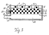
- Fig. 3 shows schematically the lower area of a reforming reactor, which in its upper area has a structure according to Fig. 1 or 2, again functionally identical elements are provided with the same reference numerals and reference is made to the description of Figs. 1 and 2 can.
- the reaction space 1 is delimited on the underside by a perforated support plate 21 on which the catalyst pellet bed 2 is seated.
- the temperature control fluid channels 3 and the intermediate tubular reaction space channels 1 a end on the underside at a distance above the carrier plate 21, so that a lower reaction space area 1 c is formed which is completely filled with the catalyst pellet bed 2.
- a gas antechamber 22 which in the present case acts as a gas outlet space, is also connected within the reactor housing 8 and can alternatively also function as a gas inlet space.
- the gas which has reacted in the reaction space 1 and which has passed through the perforated support plate 21 collects in the gas outlet space 22 Reformate gas and can be led out of the reactor housing 8 via an outlet opening 23, which can alternatively also function as an inlet opening and is introduced into a lateral reactor housing wall 8b.
- the reactor of FIG. 3 has a removal device.
- This includes an outlet pipe 24 which is inserted laterally into a housing passage opening 25, which is introduced into the reactor housing wall 8b at the level of the lower part of the lower reaction chamber region 1c, in which the outlet opening 23 is also located.
- the outlet pipe can be closed by a screw-in plunger 26 at the level of the housing passage opening 25.
- the outlet pipe 24 can be covered by a screw-on outlet pipe cover 27.
- FIG. 3 shows that the invention can be used to implement reforming reactors which are also particularly suitable for mobile applications with limited installation space, in which not only a position-securing fixation of the catalyst pellet bed in the reaction space is ensured and in a relatively simple and advantageous manner Catalyst pellet material can be refilled in the reaction space, but in addition, catalyst pellet material can be drained out of the reaction space without any complicated dismantling processes on the reactor housing.
- reforming reactors according to the invention can, if required, comprise several of the reaction space arrangements shown connected in parallel or in series.
- both reformer reactors of the tube bundle reactor type and of the plate reactor type can be implemented with catalyst pellet beds under pressure in the reaction spaces and with the filling or removal devices explained.
Landscapes
- Chemical & Material Sciences (AREA)
- Chemical Kinetics & Catalysis (AREA)
- Organic Chemistry (AREA)
- Engineering & Computer Science (AREA)
- Health & Medical Sciences (AREA)
- General Health & Medical Sciences (AREA)
- Combustion & Propulsion (AREA)
- Inorganic Chemistry (AREA)
- Life Sciences & Earth Sciences (AREA)
- Manufacturing & Machinery (AREA)
- Sustainable Development (AREA)
- Sustainable Energy (AREA)
- Electrochemistry (AREA)
- General Chemical & Material Sciences (AREA)
- Hydrogen, Water And Hydrids (AREA)
- Devices And Processes Conducted In The Presence Of Fluids And Solid Particles (AREA)
Applications Claiming Priority (2)
| Application Number | Priority Date | Filing Date | Title |
|---|---|---|---|
| DE19623918 | 1996-06-15 | ||
| DE19623918 | 1996-06-15 |
Publications (3)
| Publication Number | Publication Date |
|---|---|
| EP0812802A2 true EP0812802A2 (fr) | 1997-12-17 |
| EP0812802A3 EP0812802A3 (fr) | 1998-03-25 |
| EP0812802B1 EP0812802B1 (fr) | 1999-08-18 |
Family
ID=7797035
Family Applications (1)
| Application Number | Title | Priority Date | Filing Date |
|---|---|---|---|
| EP97107906A Expired - Lifetime EP0812802B1 (fr) | 1996-06-15 | 1997-05-15 | Réacteur de reformage, spécialement pour le reformage à la vapeur de méthanol |
Country Status (3)
| Country | Link |
|---|---|
| US (1) | US5935277A (fr) |
| EP (1) | EP0812802B1 (fr) |
| DE (1) | DE59700348D1 (fr) |
Cited By (4)
| Publication number | Priority date | Publication date | Assignee | Title |
|---|---|---|---|---|
| EP0875487A1 (fr) * | 1997-03-29 | 1998-11-04 | dbb fuel cell engines GmbH | Réacteur de reformage rempli d'un catalysateur |
| WO2013034608A1 (fr) * | 2011-09-05 | 2013-03-14 | Xylowatt S.A. | Gazeifieur de combustible solide carbone |
| WO2014065923A1 (fr) * | 2012-10-22 | 2014-05-01 | Intelligent Energy, Inc. | Générateur d'hydrogène |
| EP4485590A1 (fr) * | 2023-06-29 | 2025-01-01 | Robert Bosch GmbH | Dispositif électrochimique, en particulier dispositif de pile à combustible |
Families Citing this family (13)
| Publication number | Priority date | Publication date | Assignee | Title |
|---|---|---|---|---|
| US6749814B1 (en) | 1999-03-03 | 2004-06-15 | Symyx Technologies, Inc. | Chemical processing microsystems comprising parallel flow microreactors and methods for using same |
| US6376708B1 (en) * | 2000-04-11 | 2002-04-23 | Monsanto Technology Llc | Process and catalyst for dehydrogenating primary alcohols to make carboxylic acid salts |
| US6896848B1 (en) * | 2000-12-19 | 2005-05-24 | Tekcel, Inc. | Microplate cover assembly |
| GB0113789D0 (en) * | 2001-06-06 | 2001-07-25 | Kvaerner Process Tech Ltd | Process |
| DE20118741U1 (de) * | 2001-11-17 | 2002-02-21 | Linde Ag, 65189 Wiesbaden | Reaktor |
| DE10233820A1 (de) * | 2002-07-25 | 2004-02-12 | Thyssenkrupp Encoke Gmbh | Spaltreaktor für eine Claus-Anlage |
| DE10233819A1 (de) * | 2002-07-25 | 2004-02-12 | Thyssenkrupp Encoke Gmbh | Verfahren zur Abtrennung von Schwefelwasserstoff aus Koksofengas mit nachfolgender Gewinnung von elementarem Schwefel in einer Claus-Anlage |
| WO2004035466A1 (fr) * | 2002-10-18 | 2004-04-29 | Monsanto Technology Llc | Catalyseur au cuivre a support metallique pour reformage des alcools |
| CN101529075B (zh) * | 2006-06-13 | 2012-07-18 | 孟山都技术公司 | 重整醇动力系统 |
| KR100998812B1 (ko) * | 2008-06-13 | 2010-12-06 | 파나소닉 주식회사 | 연료 처리 장치 |
| DE102009013598A1 (de) * | 2008-09-19 | 2010-03-25 | Mtu Onsite Energy Gmbh | Brennstoffzellenanordnung mit verbessertem katalytischen Brenner |
| DE102021203887A1 (de) * | 2021-04-19 | 2022-10-20 | Forschungszentrum Jülich GmbH | Verfahren und Vorrichtung zum katalytischen Freisetzen eines Gases aus einem Trägermaterial |
| KR102734972B1 (ko) * | 2024-03-21 | 2024-11-28 | 주식회사 미코파워 | 연료전지용 개질기 및 이를 포함하는 연료전지 시스템 |
Family Cites Families (11)
| Publication number | Priority date | Publication date | Assignee | Title |
|---|---|---|---|---|
| CH366824A (de) * | 1958-03-05 | 1963-01-31 | Knapsack Ag | Verfahren und Vorrichtung zur Verteilung von Feststoffen |
| DE3601366C2 (de) * | 1986-01-18 | 1995-08-31 | Metallgesellschaft Ag | Verfahren zum Einfüllen von körnigem Katalysatormaterial in die Rohre eines Röhrenreaktors und eine Vorrichtung hierzu |
| JPS632102A (ja) * | 1986-06-20 | 1988-01-07 | Matsushita Electric Ind Co Ltd | 周波数変換装置 |
| JP2523284B2 (ja) * | 1986-07-15 | 1996-08-07 | ヤマハ発動機株式会社 | 燃料電池用改質装置 |
| JPS63310703A (ja) * | 1987-06-13 | 1988-12-19 | Fuji Electric Co Ltd | メタノ−ル改質器 |
| JPH0218303A (ja) * | 1988-07-07 | 1990-01-22 | Mitsubishi Gas Chem Co Inc | 炭化水素の改質反応器および改質方法 |
| US5445781A (en) * | 1991-08-28 | 1995-08-29 | Centro Sviluppo Settori Impiego S.R.L. | Process for the injection molding of non-precatalyzed polymerizable resins at high-pressure and flow |
| US5585075A (en) * | 1994-04-28 | 1996-12-17 | Softard Industries Co., Ltd. | Catalyst loading structure and a loading method for a reactor |
| DE4420752A1 (de) * | 1994-06-15 | 1995-09-14 | Daimler Benz Ag | Zweistufige Methanol-Reformierung |
| DE4423587C2 (de) * | 1994-07-06 | 1996-09-05 | Daimler Benz Ag | Vorrichtung zur Wasserstoffgewinnung mittels partieller Oxidation und/oder Wasserdampfreformierung von Methanol |
| US5687780A (en) * | 1995-02-14 | 1997-11-18 | Idemitsu Engineering Co., Ltd | Method of feeding catalyst and apparatus for the same |
-
1997
- 1997-05-15 DE DE59700348T patent/DE59700348D1/de not_active Expired - Fee Related
- 1997-05-15 EP EP97107906A patent/EP0812802B1/fr not_active Expired - Lifetime
- 1997-06-16 US US08/876,390 patent/US5935277A/en not_active Expired - Fee Related
Cited By (6)
| Publication number | Priority date | Publication date | Assignee | Title |
|---|---|---|---|---|
| EP0875487A1 (fr) * | 1997-03-29 | 1998-11-04 | dbb fuel cell engines GmbH | Réacteur de reformage rempli d'un catalysateur |
| US6696027B1 (en) | 1997-03-29 | 2004-02-24 | Ballard Power Systems Ag | Reformation reactor with catalyst charging |
| WO2013034608A1 (fr) * | 2011-09-05 | 2013-03-14 | Xylowatt S.A. | Gazeifieur de combustible solide carbone |
| WO2014065923A1 (fr) * | 2012-10-22 | 2014-05-01 | Intelligent Energy, Inc. | Générateur d'hydrogène |
| US9705145B2 (en) | 2012-10-22 | 2017-07-11 | Intelligent Energy Inc. | Hydrogen generator |
| EP4485590A1 (fr) * | 2023-06-29 | 2025-01-01 | Robert Bosch GmbH | Dispositif électrochimique, en particulier dispositif de pile à combustible |
Also Published As
| Publication number | Publication date |
|---|---|
| EP0812802A3 (fr) | 1998-03-25 |
| DE59700348D1 (de) | 1999-09-23 |
| US5935277A (en) | 1999-08-10 |
| EP0812802B1 (fr) | 1999-08-18 |
Similar Documents
| Publication | Publication Date | Title |
|---|---|---|
| EP0812802B1 (fr) | Réacteur de reformage, spécialement pour le reformage à la vapeur de méthanol | |
| DE69806658T2 (de) | Vorrichtung für die Reformierung von Kraftstoffen | |
| DE19639150C2 (de) | Zentrale Heizvorrichtung für ein Gaserzeugungssystem | |
| DE69924682T2 (de) | Vorrichtung zur Herstellung von Wasserstoff | |
| DE19813053C2 (de) | Reaktoreinheit für eine katalytische chemische Reaktion, insbesondere zur katalytischen Methanolreformierung | |
| EP0402783B1 (fr) | Réacteur | |
| DE60129686T2 (de) | Reaktor für exothermische oder endothermische heterogene reaktionen | |
| DE19727589B4 (de) | Vorrichtung und Verfahren zum Starten der Vorrichtung zur Erzeugung von wasserstoffreichem Gas | |
| EP2458471B1 (fr) | Dispositif thermostatique pour le réglage d'un flux de matière | |
| DE69902077T2 (de) | Vorrichtung zur Reinigung von Wasserstoff | |
| DE60020731T2 (de) | Kraftstoffrückführventil mit entlüftung | |
| EP0787679A1 (fr) | Procédé et dispositif pour la récupération d'un gaz riche en hydrogène et pauvre en monoxyde de carbone | |
| EP0814054B1 (fr) | Réacteur de reformage, spécialement pour le reformage à la vapeur de méthanol | |
| DE10061035A1 (de) | Einspritzeinrichtung zum dosierten Einspritzen von zwei Flüssigkeiten in einem Reaktionsraum | |
| DE69307542T2 (de) | Lastnachlaufverdampfer und verfahren | |
| DE69509172T2 (de) | Kernreaktorbrennstabbündel mit als unterer Befestigungsplatte ausgeführter Filter | |
| DE10136768B4 (de) | Brennstoffzellenanlage mit zwei Umformeinheiten zur katalytischen Dekomposition und Verfahren zur katalytischen Dekomposition | |
| DE102004063151A1 (de) | Reformer für eine Brennstoffzelle | |
| EP1134829B1 (fr) | Méthode et dispositif pour réduire le temps de démarrage dans des systèmes mobiles de piles à combustible | |
| DE19725008C1 (de) | Verfahren zum Betrieb einer Methanolreformierungsanlage | |
| EP3860750B1 (fr) | Dispositif de lit fixe | |
| EP1129988B1 (fr) | Méthode pour opérer un dispositif de production de gaz ou un système de piles à combustible ,dispositif de production de gaz et système de piles à combustible | |
| EP1216200B1 (fr) | Systeme de production de gaz | |
| DE19717067C2 (de) | Reformierungsreaktoranlage, insbesondere zur Wasserdampfreformierung von Methanol | |
| DE19713242C2 (de) | Reformierungsreaktor zur Wasserdampfreformierung von Methanol |
Legal Events
| Date | Code | Title | Description |
|---|---|---|---|
| PUAI | Public reference made under article 153(3) epc to a published international application that has entered the european phase |
Free format text: ORIGINAL CODE: 0009012 |
|
| AK | Designated contracting states |
Kind code of ref document: A2 Designated state(s): DE FR GB IT |
|
| PUAL | Search report despatched |
Free format text: ORIGINAL CODE: 0009013 |
|
| AK | Designated contracting states |
Kind code of ref document: A3 Designated state(s): DE FR GB IT |
|
| 17P | Request for examination filed |
Effective date: 19980226 |
|
| RAP1 | Party data changed (applicant data changed or rights of an application transferred) |
Owner name: DBB FUEL CELL ENGINES GESELLSCHAFT MIT BESCHRAENKT |
|
| 17Q | First examination report despatched |
Effective date: 19980612 |
|
| GRAG | Despatch of communication of intention to grant |
Free format text: ORIGINAL CODE: EPIDOS AGRA |
|
| GRAG | Despatch of communication of intention to grant |
Free format text: ORIGINAL CODE: EPIDOS AGRA |
|
| GRAH | Despatch of communication of intention to grant a patent |
Free format text: ORIGINAL CODE: EPIDOS IGRA |
|
| GRAH | Despatch of communication of intention to grant a patent |
Free format text: ORIGINAL CODE: EPIDOS IGRA |
|
| GRAA | (expected) grant |
Free format text: ORIGINAL CODE: 0009210 |
|
| AK | Designated contracting states |
Kind code of ref document: B1 Designated state(s): DE FR GB IT |
|
| REF | Corresponds to: |
Ref document number: 59700348 Country of ref document: DE Date of ref document: 19990923 |
|
| GBT | Gb: translation of ep patent filed (gb section 77(6)(a)/1977) |
Effective date: 19990922 |
|
| ET | Fr: translation filed | ||
| PLBE | No opposition filed within time limit |
Free format text: ORIGINAL CODE: 0009261 |
|
| STAA | Information on the status of an ep patent application or granted ep patent |
Free format text: STATUS: NO OPPOSITION FILED WITHIN TIME LIMIT |
|
| 26N | No opposition filed | ||
| REG | Reference to a national code |
Ref country code: FR Ref legal event code: CD |
|
| REG | Reference to a national code |
Ref country code: GB Ref legal event code: IF02 |
|
| REG | Reference to a national code |
Ref country code: FR Ref legal event code: CD |
|
| REG | Reference to a national code |
Ref country code: FR Ref legal event code: TP Ref country code: FR Ref legal event code: CD |
|
| PGFP | Annual fee paid to national office [announced via postgrant information from national office to epo] |
Ref country code: IT Payment date: 20090527 Year of fee payment: 13 Ref country code: FR Payment date: 20090513 Year of fee payment: 13 Ref country code: DE Payment date: 20090525 Year of fee payment: 13 |
|
| PGFP | Annual fee paid to national office [announced via postgrant information from national office to epo] |
Ref country code: GB Payment date: 20090522 Year of fee payment: 13 |
|
| GBPC | Gb: european patent ceased through non-payment of renewal fee |
Effective date: 20100515 |
|
| REG | Reference to a national code |
Ref country code: FR Ref legal event code: ST Effective date: 20110131 |
|
| PG25 | Lapsed in a contracting state [announced via postgrant information from national office to epo] |
Ref country code: IT Free format text: LAPSE BECAUSE OF NON-PAYMENT OF DUE FEES Effective date: 20100515 |
|
| PG25 | Lapsed in a contracting state [announced via postgrant information from national office to epo] |
Ref country code: DE Free format text: LAPSE BECAUSE OF NON-PAYMENT OF DUE FEES Effective date: 20101201 |
|
| PG25 | Lapsed in a contracting state [announced via postgrant information from national office to epo] |
Ref country code: FR Free format text: LAPSE BECAUSE OF NON-PAYMENT OF DUE FEES Effective date: 20100531 |
|
| PG25 | Lapsed in a contracting state [announced via postgrant information from national office to epo] |
Ref country code: GB Free format text: LAPSE BECAUSE OF NON-PAYMENT OF DUE FEES Effective date: 20100515 |