EP0402836A2 - Bilderzeugunsgerät - Google Patents
Bilderzeugunsgerät Download PDFInfo
- Publication number
- EP0402836A2 EP0402836A2 EP90111018A EP90111018A EP0402836A2 EP 0402836 A2 EP0402836 A2 EP 0402836A2 EP 90111018 A EP90111018 A EP 90111018A EP 90111018 A EP90111018 A EP 90111018A EP 0402836 A2 EP0402836 A2 EP 0402836A2
- Authority
- EP
- European Patent Office
- Prior art keywords
- sheet
- rollers
- image forming
- path
- feeding means
- Prior art date
- Legal status (The legal status is an assumption and is not a legal conclusion. Google has not performed a legal analysis and makes no representation as to the accuracy of the status listed.)
- Granted
Links
Images

Classifications
-
- G—PHYSICS
- G03—PHOTOGRAPHY; CINEMATOGRAPHY; ANALOGOUS TECHNIQUES USING WAVES OTHER THAN OPTICAL WAVES; ELECTROGRAPHY; HOLOGRAPHY
- G03G—ELECTROGRAPHY; ELECTROPHOTOGRAPHY; MAGNETOGRAPHY
- G03G15/00—Apparatus for electrographic processes using a charge pattern
- G03G15/65—Apparatus which relate to the handling of copy material
- G03G15/6555—Handling of sheet copy material taking place in a specific part of the copy material feeding path
- G03G15/6579—Refeeding path for composite copying
-
- G—PHYSICS
- G03—PHOTOGRAPHY; CINEMATOGRAPHY; ANALOGOUS TECHNIQUES USING WAVES OTHER THAN OPTICAL WAVES; ELECTROGRAPHY; HOLOGRAPHY
- G03G—ELECTROGRAPHY; ELECTROPHOTOGRAPHY; MAGNETOGRAPHY
- G03G15/00—Apparatus for electrographic processes using a charge pattern
- G03G15/22—Apparatus for electrographic processes using a charge pattern involving the combination of more than one step according to groups G03G13/02 - G03G13/20
- G03G15/23—Apparatus for electrographic processes using a charge pattern involving the combination of more than one step according to groups G03G13/02 - G03G13/20 specially adapted for copying both sides of an original or for copying on both sides of a recording or image-receiving material
- G03G15/231—Arrangements for copying on both sides of a recording or image-receiving material
- G03G15/232—Arrangements for copying on both sides of a recording or image-receiving material using a single reusable electrographic recording member
- G03G15/234—Arrangements for copying on both sides of a recording or image-receiving material using a single reusable electrographic recording member by inverting and refeeding the image receiving material with an image on one face to the recording member to transfer a second image on its second face, e.g. by using a duplex tray; Details of duplex trays or inverters
-
- G—PHYSICS
- G03—PHOTOGRAPHY; CINEMATOGRAPHY; ANALOGOUS TECHNIQUES USING WAVES OTHER THAN OPTICAL WAVES; ELECTROGRAPHY; HOLOGRAPHY
- G03G—ELECTROGRAPHY; ELECTROPHOTOGRAPHY; MAGNETOGRAPHY
- G03G2215/00—Apparatus for electrophotographic processes
- G03G2215/00362—Apparatus for electrophotographic processes relating to the copy medium handling
- G03G2215/00367—The feeding path segment where particular handling of the copy medium occurs, segments being adjacent and non-overlapping. Each segment is identified by the most downstream point in the segment, so that for instance the segment labelled "Fixing device" is referring to the path between the "Transfer device" and the "Fixing device"
- G03G2215/00417—Post-fixing device
- G03G2215/00421—Discharging tray, e.g. devices stabilising the quality of the copy medium, postfixing-treatment, inverting, sorting
-
- G—PHYSICS
- G03—PHOTOGRAPHY; CINEMATOGRAPHY; ANALOGOUS TECHNIQUES USING WAVES OTHER THAN OPTICAL WAVES; ELECTROGRAPHY; HOLOGRAPHY
- G03G—ELECTROGRAPHY; ELECTROPHOTOGRAPHY; MAGNETOGRAPHY
- G03G2215/00—Apparatus for electrophotographic processes
- G03G2215/00362—Apparatus for electrophotographic processes relating to the copy medium handling
- G03G2215/00367—The feeding path segment where particular handling of the copy medium occurs, segments being adjacent and non-overlapping. Each segment is identified by the most downstream point in the segment, so that for instance the segment labelled "Fixing device" is referring to the path between the "Transfer device" and the "Fixing device"
- G03G2215/00417—Post-fixing device
- G03G2215/0043—Refeeding path
- G03G2215/00438—Inverter of refeeding path
-
- Y—GENERAL TAGGING OF NEW TECHNOLOGICAL DEVELOPMENTS; GENERAL TAGGING OF CROSS-SECTIONAL TECHNOLOGIES SPANNING OVER SEVERAL SECTIONS OF THE IPC; TECHNICAL SUBJECTS COVERED BY FORMER USPC CROSS-REFERENCE ART COLLECTIONS [XRACs] AND DIGESTS
- Y10—TECHNICAL SUBJECTS COVERED BY FORMER USPC
- Y10S—TECHNICAL SUBJECTS COVERED BY FORMER USPC CROSS-REFERENCE ART COLLECTIONS [XRACs] AND DIGESTS
- Y10S271/00—Sheet feeding or delivering
- Y10S271/902—Reverse direction of sheet movement
Definitions
- the present invention relates to an image forming apparatus having a sheet re-supplying path for forming at least two images on the same sheet.
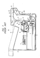
- LBP laser beam printer
- the laser beam printer 1d includes a body 2 having a bottom on which a cassette 3 accommodating sheets S is disposed.
- a sheet supply roller 5 is arranged above the front part of the cassette 3 to separate and supply the sheets one by one.
- a pair of regist rollers 6 for maintaining a leading end of the sheet picked-up by the supply roller 5 in a correct position to ensure good recording accuracy of an image, and a process unit 10 comprising functional portions such as a photosensitive drum 7, a developing device 9 and the like.
- a laser scanning unit 11 illuminates a laser beam on the photosensitive drum 7 on the basis of image information from an apparatus body (not shown) to form a latent image on the drum.
- the latent image is developed by the developing device 9 to form a toner image which is in turn transferred onto the sheet S fed by the supply roller 5 and pressed against the photosensitive drum 7 by a transfer roller 12.
- the sheet S having the transferred image thereon is fixed by a fixing device 13 including fixing rollers arranged at a downstream side of the transfer roller 12, and then is fed to a pair of feed rollers 15 and then to a downstream flapper 16.
- the flapper 16 is in a position rotated in an anti-clockwise direction, where the sheet on which the image has been recorded is directed toward an sheet ejecting path 19 through which the sheet S is ejected onto an ejector tray 17 with a recorded surface thereof turned inside.
- the flapper 16 is rotated in a clockwise direction from the position of Fig. 1 to a "both-surface" position, the sheet S is directed toward sheet guides 22 of a switch-back unit 21 and then is pinched or nipped and fed by reversible rollers 23.
- a trailing end of the sheet S is detected by a sensor 25 arranged at a downstream side of the sheet guides 22, the reversible rollers 23 are rotated reversely to feed the sheet in the reverse direction.
- the sheet S fed in the reverse direction is directed toward a sheet feeding path 26 for a second surface recording (sheet re-supplying path) by a flapper 25 disposed at an upstream side of the reversible rollers 23, and then is fed toward re-supply rollers 29 by means of feed rollers 27 disposed in the sheet re-supplying path.
- the flapper is spring-biased to normally occupy the position shown by a solid line in Fig. 1, and the sheet fed from the sheet guides 22 reaches the reversible rollers 23 while urging the flapper 25 downwardly.
- the flapper 25 When the trailing end of the sheet has passed through the flapper 25, the latter is returned to the position shown in Fig. 1.
- the sheet feeding path 26 for the second surface recording is driven independently from that of a sheet feeding path 20 for a first surface recording, since it must be controlled independently from the sheet feeding path 20.
- a sensor 30 for the second surface recording is arranged at a downstream side of the resupply rollers 29. When the sensor 30 detects the leading end of the sheet S, the sheet is stopped, whereby the timing of the sheet supply for the second surface recording is controlled.
- the sheet re-supplying path 26 includes a path section 26a positioned between the reversible rollers 23 and the feed rollers 27, a path section 26b positioned between the feed rollers 27 and the re-supply rollers 29, and a path section 26c positioned between the re-supply rollers 29 and the regist rollers 6. Since the sheet S is switched back in the switchback unit 21, in the sheet feeding path 26 for the second surface recording, the first recorded surface of the sheet S faces toward the photosensitive drum 7; but, the sheet S is U-turned in the path section 26c so that the second non-recorded surface of the sheet faces the photosensitive drum 7 when the image is recorded on the sheet again.
- the sheet feeding path for the second surface recording is normally shorter than the twice of the maximum length of the sheet S to be re-supplied.
- the second sheet S cannot be fed to the sheet feeding path 20.
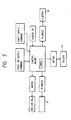
- the recording is effected, in order, for the first surface of the first sheet, second surface of the first sheet, first surface of second sheet, second surface of the second sheet, ... first surface of (N - 1)th sheet, second surface of the (N - 1)th sheet, first surface of Nth sheet, second surface of the Nth sheet, and so on.
- first surface of a new sheet cannot be recorded till after the second surface of the previous sheet has been recorded, the through-put was considerably worsened when the image were on both surfaces of the same sheet.
- an object of the present invention is to provide an image forming apparatus having a sheet re-supplying path which can store at least two sheets in a sheet feeding path for a second surface recording (sheet re-supplying path) whereby the through-put in the both-surface recording is maintained as the same as that in the single-surface recording.
- the present invention provides an image forming apparatus comprising, for example, an image forming means for forming an image on a sheet; a sheet re-supplying path for re-supplying the sheet having one surface on which the image has been recorded to the image forming means again; and at least two sheet stop positions (first and second sheet stop positions) situated in the sheet re-supplying path; and wherein a distance between the two sheet stop positions is selected to be smaller than a maximum length of the sheet to be fed, and at least two successive sheets (first and second sheets) stored in the sheet re-supplying path can be independently stopped in the first and second sheet stop positions and be independently fed.
- the sheet is fed to an image forming portion where the image is formed on the sheet.
- the first sheet previously fed is fed to the first sheet stop position in the sheet re-supplying path and is stopped there.
- the second sheet successively fed is fed to the second sheet stop position in the sheet re-supplying path and is stopped there with partially overlapping with the first sheet.
- the first and second sheets can be stopped and fed independently in the sheet re-supplying path, in spite of the fact that the distance between the first and second sheet stop positions is smaller than the maximum length of the sheet, and the first sheet is re-supplied to the image forming portion while the second sheet is stopped in the second sheet stop position. In this way, the both-surface recording or multi-recording is effected while a plurality of sheets are successively fed in the sheet re-supplying path.
- the through-put in the both-surface recording or multi-recording can be maintained as the same as that in the single-surface recording while keeping the apparatus small-sized.
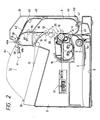
- the image forming apparatus 1a such as a laser beam printer or the like includes a cassette 3 accommodating sheets S therein, which cassette 3 can be inserted into and removed from a body 2 of the apparatus from a rightward direction of Fig. 2.
- a separating pad 5a is incorporated into the front part of the cassette 3 and is formed integrally with cam members (not shown) projecting from both sides of the cassette 3. The separating pad 5a cooperates with cam surfaces (not shown) formed on cassette guides (not shown) of the body 2 to engage with or disengage from a sheet supply roller 5 in response to the insertion or removal of the cassette 3.
- the sheets S in the cassette 3 are fed one by one by means of the supply roller 5 to a pair of regist rollers 6 (now stopped) while preventing the double-feed of the sheets by the separating pad 5a. While the sheet S is being fed to the regist rollers 6, a loop is formed in the sheet, whereby a leading end of the sheet is aligned with the nip of the regist rollers to correct the skew-feed of the sheet.
- the sheet S is fed, by the regist rollers 6 which are rotated after the formation of the loop in the sheet, to an image forming portion 33 comprising a photosensitive drum 7 of a process unit 20 and a sheet feeding path 26, where a toner image is transferred onto the sheet.
- the toner image is then fixed to the sheet by a fixing device 13. If an image is recorded on a single surface of the sheet (single-surface recording), the sheet S is guided by a flapper 16 and an ejecting path 19 is ejected onto an ejector tray 17 with a recorded surface thereof turned inside.
- a switch-back unit 35 can optionally be arranged.
- the apparatus body 2 includes a sheet feeding path 36 for a second surface recording alone, but does not include feed rollers and the like.
- first feed rollers 37 which are disposed at a downstream side of the flapper 16 and which can be stopped and rotated, and a sheet feeding path 39.
- a pair of cooperating reversible rollers 40 At a downstream side of the sheet feeding path 39, there are arranged a pair of cooperating reversible rollers 40.
- the reversible rollers 40 comprise a reversible roller 40a driven by a driving source (not shown) and a driving roller 40b pressed against and driven by the roller 40a.
- the driven roller 40b can also be separated from the reversible roller 40a by means of a sheet feeding force interrupting mechanism (plunger, rinks, spring) 41.
- a shiftable lateral regist guide 42 for correcting the lateral regist of the sheet S for the second surface recording, and second sheet feed rollers 43 are disposed. Further, at a downstream side of the second feed rollers 43, there are arranged, in order, sheet feeding paths 45, 46, regist rollers 47 for the sheet for the second surface recording, and a sheet feeding path 49 a downstream end of which is disposed in the vicinity of the regist rollers 6.
- the flapper 16 When the images are to be recorded on both surfaces of the sheet (both-surface recording), the flapper 16 is rotated in a clockwise direction from a position shown in Fig. 2, where the sheet S on which the toner image has been fixed by the fixing device 13 is fed to the switch-back unit 35 by means of the feed roller pair 15. In the switch-back unit 35, the sheet S having the first surface on which the image has been recorded is fed to the reversible roller pair 40 through the first feed rollers 37.
- the sheet S is once fed out toward the ejector tray 17 by the reversible rollers 40 when a trailing end of the sheet S is detected by a sensor 50 arranged in the vicinity of the reversible rollers 40, the reversible rollers are rotated reversely to feed the sheet S in the sheet feeding paths 45, 46 for the second surface recording.
- the sheet S fed in the sheet feeding paths 45, 46 is temporarily stopped against the both-surface recording regist rollers 47 acting also as rollers for a manual inserted sheet (the manual insert sheet is inserted from an insertion inlet formed in the body 2), thereby correcting the leading end regist and skew-feed of the sheet. Thereafter, the first sheet S is further fed slightly and is stopped there for waiting a print signal for the second surface recording.
- the trailing end of the first sheet S is in a condition that it is pinched by the reversible rollers 40.
- a position where the first sheet S is pinched by the both-surface recording regist rollers 47 will be referred as a first sheet stop position A (the leading end of the sheet is shown by A1 and the trailing end A2).
- the reversible rollers 40 are stopped and at the same time the driven roller 40b is separated from the roller 40a by the sheet feeding force interrupting mechanism 41.
- the second sheet S which has been fed from the cassette 3 and on which the image has been formed is fed to the reversible rollers by means of the first feed rollers 37 in the switchback unit 35.
- the reversible rollers 40 are separated from each other as mentioned above if these rollers are stopped, the sheet S can pass through the clearance between the rollers 40.
- the first feed rollers 37 are stopped after a predetermined time has been elapsed, i.e., when the trailing end of the second sheet S has passed through the sheet feeding paths 20, 36 but has not yet passed through the first feed rollers 37.
- a position where the trailing end of the second sheet S is pinched by the first feed rollers 37 will be referred as a second sheet stop position B (the leading end of the sheet is shown by B1 and the trailing end B2).
- a driving system (not shown) receives a print signal for the second surface recording of the first sheet
- the both-surface recording regist rollers 47 are rotated, so that the first sheet S which is now waiting in the sheet feeding paths 45, 46 is fed to the image forming portion 3 through the regist rollers 6.
- the second surface recording of the first sheet is effected, and then the first sheet is ejected on the ejector tray 17.
- the driven rollers 40b is pressed against the reversible roller 40a again by the action of the sheet feeding force interrupting mechanism 41, thereby pinching the second sheet S.
- the second sheet S so pinched is once fed toward the ejector tray 17 (left) by the normal rotation of the reversible rollers 40 when the trailing end of the second sheet is detected by the sensor 50, the second sheet S is fed in the sheet feeding paths 45, 46 through the reverse rotation of the reversible rollers 40, with the result that, as in the case of the first sheet, the second sheet is waiting for the second surface recording with being pinched by the rollers 47.
- Fig. 3 shows an elevational sectional view of an image forming apparatus having a sheet re-supplying path according to a second embodiment of the present invention.
- the same elements as shown in Fig. 2 are designated by the same reference numerals and the explanation thereof will be omitted.
- a flapper 61 is arranged at a downstream side of the first feed rollers 37, which flapper is rotatably supported by a pin 62.
- the flapper 61 is so designed that when a solenoid (not shown) is energized the flapper is rotated to a position shown by a solid line in Fig. 3 and when the solenoid is de-energized the flapper is rotated to a position shown by a two-dot and chain line in Fig. 3.
- a pair of cooperating rollers 63 which comprise a feeding roller 63a tending to feed the sheet S in a direction shown by the arrow, i.e., in the right direction of Fig. 3 and a driven roller 63b biased to be pressed against the feeding roller by means of a spring (not shown).
- a cam surface 61a is integrally formed on the left end (Fig. 3) of the flapper 61.
- the cam surface 61a is engaged by a shaft 65 of the driven roller 63b to lift the latter thereby separating the driven roller 63b from the feeding roller 63a.
- the cam surface 61a is disengaged from the shaft 65, thereby allowing the driven roller 63b to be pressed against the feeding roller 63a by the force of the spring (not shown).
- the first sheet being fed by the first feed rollers 37 is guided by the flapper 61 positioned in the illustrated position by the energization of the solenoid (not shown) and then passes through a space between the feeding roller 63a and the driven roller 63b separated from the feeding roller.
- the first sheet S is then pinched and held by the first feed rollers 37 which are stopped immediately before the trailing end of the first sheet S passes through the rollers 37. In this case, the feeding roller 63a is maintained in the stopped condition.
- the solenoid connected to the flapper 612 is disenergized to rotate the flapper 61 to the position shown by the two-dot and chain line, with the result that the trailing end portion of the sheet is lifted by the flapper 61 to be pressed against the roller 66.
- the driven roller 63b is pressed against the feeding roller 63a, thus pinching the sheet S therebetween. In this condition, by rotating the pair of cooperating rollers 63, the sheet S is fed to the sheet feeding paths 45, 46 while being guided by the flapper 61.
- one-way clutches may be provided between the first feed rollers 37 and shafts (not shown) supporting the first feed rollers, so that, when the sheet S pinched by the first feed rollers 37 is drawn out, the first feed rollers 37 can be freely rotated on the corresponding shafts, whereby the operation that the sheet S is drawn out of the nip between the first feed rollers 37 and is pressed against the roller 66 upon the rotation of the flapper 61 toward the two-dot and chain position can be smoothly be effected.
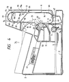
- Fig. 4 shows an elevational sectional view of a laser beam printer (image forming apparatus) 1c according to a third embodiment of the present invention.
- the present invention is applied to a printer which can record or print an image with two or more colors (multi-printing).
- the elements same as those shown in Fig. 2 are designated by the same reference numerals and the explanation thereof will be omitted.
- a process unit 10 includes a first developing device 71 accommodating black toner, and a second developing device 72 accommodating black toner or colored toner other than black.
- the first and second developing devices 71 and 72 can be alternately selected in response to an image signal from the apparatus body (not shown) to develop the image with the toner accommodated therein.
- a toner image developed by either first or second developing device 71 or 72 is transferred onto a sheet S fed by a supply roller 5. After the transferred image has been fixed to the sheet by a fixing device 13, the sheet S is ejected onto an ejector tray 17.
- the sheet S onto which the toner image developed by either first or second developing device 71 or 72 has been transferred is fed from the fixing device 13 to a flapper 16, by which the sheet is fed to a U-turn unit 73.
- the sheet S is then U-turned by this unit 73 and is fed to an image forming portion 33 again, where the toner image developed by the second or first developing device 72 or 72 is transferred onto the sheet S.
- the transferred image is fixed to the sheet by the fixing device 13. In this way, the two-color recording is effected on the same sheet. Thereafter, the sheet is ejected on the ejector tray 17.
- a flapper 75 for switching paths for the sheet S and a first U-turn path 77 having second feed rollers 76 are disposed at a downstream side of first feed rollers 37.
- the second feed rollers 76 are arranged in an upstream end portion of the path 77.
- a fourth pair of cooperating rollers 79 which comprises a feeding roller 79a connected to a driving system (not shown) and a driven roller 79b detachably biased against the feeding roller 79a.
- a second U-turn path 81 is provided, which path 81 is branched from the first U-turn path by the flapper 75 and has third feed rollers 80 therein. A downstream end of the second U-turn path 81 is joined to the first U-turn path 77.
- the first sheet S on which the image has been recorded with a first color is guided toward the U-turn unit 73 by means of the flapper 16, and is passed through the first feed rollers 37 to reach the flapper 75 in the U-turn unit 73.
- the sheet is then guided by the flapper 75 to be directed to the first U-turn path 77.
- the first sheet is guided by the feed rollers 76 toward the fourth roller pair 79 and the sheet feeding path 46 for the two-color recording, where the leading end regist and skew-feed of the sheet is corrected by regist rollers 47 for the two-color recording.
- the sheet is waiting for a signal for the two-color recording.
- the trailing end A2 of the first sheet S is set to be positioned in an area upstream side of the joining point 100 (between the U-turn paths 77, 81) upstream side of the nip between the feeding roller 79a and the driven roller 79b of the roller pair 79.
- the driven roller 79b is retarded to a position shown by a two-dot and chain line in Fig. 4 to be separated from the feeding roller 79a.
- the engagement and disengagement of the driven roller 79b with respect to the feeding roller 79a can be performed by a plunger and the like.
- the flapper 75 is rotated to the position shown by the two-dot and chain line to guide the second sheet to the second U-turn path 81.
- the second sheet S is guided by the third feed rollers 80 while contacting on the surface of the first sheet to be passed through a space between the separated driven roller 79b and the stopped feeding roller 79a, and is stopped in a position where the leading end B1 of the second sheet enters slightly into the sheet feeding path 46 for the two-color recording.
- the first sheet S i.e., the sheet which is waiting at the upstream side
- the second sheet S i.e., the sheet situated at the downstream side
- the feeding roller 79a which is rotated at a predetermined timing (i.e., after the trailing end of the previous sheet has passed through this roller 79a) and the driven roller 79b pressed against the feeding roller.
- a fourth embodiment will be explained in connection with Fig. 2.
- the driven roller 40b can be separated from the feeding roller 40a
- the purpose of the present invention is to hold and/or feed two sheets independently from each other, it is not necessary to separate the driven roller 40b from the feeding roller 40a.
- a so-called torque limiter mechanism 41a for interrupting the transmission of the driving force when either the reversible roller 40a or 40b is subjected to a predetermined torque or more may be provided regarding the reversible roller pair 40.
- each of the elements may be selected to give the following relationship: F3 > F2 ⁇ 2 > F1 > F2 ⁇ 1.
- the next (second) sheet S is fed or stopped in response to the movement of the driven roller 40b.
- the previous (first) sheet S is not moved if one end thereof is held by other rollers (for example, rollers 43).
- the torque limiter mechanism 41a is operated to interrupt the transmission of the driving force to the reversible roller 40a whereby the pair of reversible rollers 40 remain stationary or are rotated freely.
- the driven roller 40b feeds only the next sheet to the left (Fig. 2) by a distance substantially corresponding to the length of the sheet S are then is stopped.
- the both-surface recording regist rollers 47 start to rotate to feed the previous sheet S waiting in the sheet feeding path 46.
- the next sheet S remains stationary since it is held by the stopped driven roller 40b.
- the torque limiter mechanism 41a disposed between the reversible rollers 40 and supporting shafts therefor may comprise a torque limiter member utilizing the friction, or other members, for example, a member capable of interrupting the transmission of the driving force to the reversible roller 40a when either one of the paired reversible rollers 40 is subjected to a predetermined load or more.
- the lower roller 40b may be a driving roller
- the upper roller 40a may be a driven roller
- the present invention provides an image forming apparatus having a sheet re-supplying path, comprising an image forming means for forming an image on a sheet, a sheet re-supplying path for supplying a sheet on which the image has been formed by the image forming means to the image forming means again, a first rotatable feeding means disposed in the sheet re-supplying path for pinching and feeding a leading end portion of a previous sheet, a second rotatable feeding means disposed at an upstream side of the first rotatable feeding means in the sheet re-supplying path for permitting the entrance of a next sheet in a condition that a trailing portion of the previous sheet is situated in the second rotatable feeding means, and a control means for permitting the second rotatable feeding means to feed the next sheet after the trailing end of the previous sheet fed by the first rotatable feeding means has passed through the second rotatable feeding means.
Landscapes
- Physics & Mathematics (AREA)
- General Physics & Mathematics (AREA)
- Conveyance By Endless Belt Conveyors (AREA)
- Separation, Sorting, Adjustment, Or Bending Of Sheets To Be Conveyed (AREA)
- Counters In Electrophotography And Two-Sided Copying (AREA)
- Paper Feeding For Electrophotography (AREA)
- Registering Or Overturning Sheets (AREA)
Applications Claiming Priority (2)
| Application Number | Priority Date | Filing Date | Title |
|---|---|---|---|
| JP148714/89 | 1989-06-12 | ||
| JP1148714A JP2692957B2 (ja) | 1989-06-12 | 1989-06-12 | 再給紙搬送路を有する画像形成装置 |
Publications (3)
| Publication Number | Publication Date |
|---|---|
| EP0402836A2 true EP0402836A2 (de) | 1990-12-19 |
| EP0402836A3 EP0402836A3 (de) | 1991-05-08 |
| EP0402836B1 EP0402836B1 (de) | 1994-03-02 |
Family
ID=15458955
Family Applications (1)
| Application Number | Title | Priority Date | Filing Date |
|---|---|---|---|
| EP90111018A Expired - Lifetime EP0402836B1 (de) | 1989-06-12 | 1990-06-11 | Bilderzeugunsgerät |
Country Status (4)
| Country | Link |
|---|---|
| US (1) | US5132742A (de) |
| EP (1) | EP0402836B1 (de) |
| JP (1) | JP2692957B2 (de) |
| DE (1) | DE69006923T2 (de) |
Cited By (3)
| Publication number | Priority date | Publication date | Assignee | Title |
|---|---|---|---|---|
| EP0851310A3 (de) * | 1996-12-24 | 1998-08-05 | Canon Kabushiki Kaisha | Blattfördervorrichtung |
| EP1925990A3 (de) * | 2006-11-21 | 2009-06-24 | Samsung Electronics Co., Ltd. | Bilderzeugungsvorrichtung mit der Fähigkeit zur Erzeugung eines Duplexbildes auf einem Bogen |
| EP2026136A3 (de) * | 2007-05-07 | 2016-06-22 | Canon Kabushiki Kaisha | Bilderzeugungsvorrichtung |
Families Citing this family (33)
| Publication number | Priority date | Publication date | Assignee | Title |
|---|---|---|---|---|
| IL111846A0 (en) | 1994-12-01 | 1995-03-15 | Indigo Nv | Imaging apparatus and intermediate transfer blanket therefor |
| US5317377A (en) * | 1991-09-27 | 1994-05-31 | Xerox Corporation | Inverter apparatus capable of inverting A3 or 11×17" sheets |
| KR940003112B1 (ko) * | 1991-10-25 | 1994-04-13 | 삼성전자 주식회사 | 전자사진방식을 이용한 기기에 사용되는 카세트 |
| US5666599A (en) * | 1994-04-06 | 1997-09-09 | Hitachi, Ltd. | Color electro-photographic printing apparatus |
| US5449160A (en) * | 1994-07-29 | 1995-09-12 | Xerox Corporation | Gateless rocker inverter |
| US5680651A (en) * | 1995-05-09 | 1997-10-21 | Sharp Kabushiki Kaisha | Duplex printing apparatus |
| KR0181150B1 (ko) * | 1996-02-13 | 1999-04-01 | 김광호 | 화상형성장치의 용지경로 변경장치 |
| US5884137A (en) * | 1996-08-07 | 1999-03-16 | Konica Corporation | Two-sided copying apparatus including a reversing stop mechanism |
| JPH10139248A (ja) * | 1996-11-06 | 1998-05-26 | Canon Inc | 画像形成装置 |
| US6145834A (en) * | 1997-06-12 | 2000-11-14 | Konica Corporation | Automatic document feeder having a document shunting path |
| US6354589B1 (en) * | 1998-09-11 | 2002-03-12 | Ricoh Company, Ltd. | Sheet feed apparatus, method and computer readable medium for double-sided document sheet feed operations |
| JP3352979B2 (ja) | 1999-07-16 | 2002-12-03 | 松下電送システム株式会社 | 記録装置 |
| JP2001302114A (ja) * | 2000-01-11 | 2001-10-31 | Ricoh Co Ltd | 画像形成装置 |
| US6470169B2 (en) | 2000-01-20 | 2002-10-22 | Ricoh Company, Ltd. | Image forming apparatus and method, a printer, a copying machine, a facsimile device set, and complex machine |
| JP2002154751A (ja) * | 2000-11-17 | 2002-05-28 | Toshiba Tec Corp | 画像形成装置 |
| US6836640B2 (en) * | 2001-12-12 | 2004-12-28 | Canon Kabushiki Kaisha | Sheet conveying apparatus and image forming apparatus |
| JP2004163900A (ja) * | 2002-10-10 | 2004-06-10 | Sharp Corp | 両面画像形成装置 |
| US7376382B2 (en) * | 2004-12-16 | 2008-05-20 | Kabushiki Kaisha Toshiba | Image forming apparatus and image forming method |
| JP4513682B2 (ja) * | 2005-07-25 | 2010-07-28 | 富士ゼロックス株式会社 | 給紙装置及びそれを備えた画像形成装置 |
| JP5000901B2 (ja) * | 2006-03-02 | 2012-08-15 | 株式会社リコー | 画像形成方法及び装置 |
| KR101367128B1 (ko) * | 2007-03-26 | 2014-02-26 | 삼성전자주식회사 | 양면 인쇄 화상형성장치 |
| US7717423B2 (en) * | 2007-09-27 | 2010-05-18 | Lexmark International, Inc. | Duplex ADF mechanism |
| JP2009258562A (ja) * | 2008-04-21 | 2009-11-05 | Sharp Corp | 画像形成装置 |
| JP4609579B2 (ja) * | 2008-12-26 | 2011-01-12 | ブラザー工業株式会社 | 画像記録装置 |
| JP5448245B2 (ja) * | 2009-10-27 | 2014-03-19 | 株式会社リコー | シート材排出装置及び画像形成装置 |
| EP2628054B1 (de) | 2010-10-13 | 2014-12-10 | Canon Kabushiki Kaisha | Blattfördervorrichtung und bilderzeugungsvorrichtung |
| JP5208252B2 (ja) * | 2010-10-13 | 2013-06-12 | キヤノン株式会社 | シート搬送装置及び画像形成装置並びに画像読取装置 |
| JP5922058B2 (ja) * | 2013-04-26 | 2016-05-24 | 株式会社東芝 | 分別装置、検知方法 |
| JP6052115B2 (ja) * | 2013-09-12 | 2016-12-27 | カシオ電子工業株式会社 | 印刷装置 |
| JP5915865B2 (ja) * | 2013-09-30 | 2016-05-11 | コニカミノルタ株式会社 | 画像形成装置、画像形成システムおよび画像形成方法 |
| JP6446946B2 (ja) * | 2014-09-25 | 2019-01-09 | ブラザー工業株式会社 | 搬送装置及びインクジェット記録装置 |
| JP6500561B2 (ja) * | 2015-03-31 | 2019-04-17 | ブラザー工業株式会社 | 画像形成装置 |
| US10289067B2 (en) * | 2015-06-09 | 2019-05-14 | Ricoh Company, Ltd. | Image forming apparatus |
Family Cites Families (12)
| Publication number | Priority date | Publication date | Assignee | Title |
|---|---|---|---|---|
| US4040616A (en) * | 1976-01-14 | 1977-08-09 | Xerox Corporation | Sheet turn around/inverter |
| US4573789A (en) * | 1982-04-13 | 1986-03-04 | Minolta Camera Kabushiki Kaisha | Duplex copying system |
| JPS6247655A (ja) * | 1985-08-28 | 1987-03-02 | Toshiba Corp | 両面印刷方法 |
| JP2611199B2 (ja) * | 1986-05-23 | 1997-05-21 | 日立工機株式会社 | カツト紙レーザビームプリンタ |
| JPH0825695B2 (ja) * | 1986-05-30 | 1996-03-13 | 日立工機株式会社 | 両面印刷装置 |
| GB2196942B (en) * | 1986-09-18 | 1991-07-17 | Canon Kk | A sheet conveying apparatus |
| JPH0639310B2 (ja) * | 1986-11-20 | 1994-05-25 | キヤノン株式会社 | 画像形成装置 |
| JPS63313172A (ja) * | 1987-06-16 | 1988-12-21 | Canon Inc | 両面記録装置の制御方法 |
| US4990965A (en) * | 1988-04-15 | 1991-02-05 | Ricoh Company, Ltd. | Image forming apparatus having duplex unit |
| US4943832A (en) * | 1988-06-09 | 1990-07-24 | Minolta Camera Kabushiki Kaisha | Image forming apparatus |
| US4935786A (en) * | 1989-06-28 | 1990-06-19 | Digital Equipment Corporation | Method and apparatus for duplex printing |
| US4918490A (en) * | 1989-07-19 | 1990-04-17 | Xerox Corporation | Batch mode duplex printing |
-
1989
- 1989-06-12 JP JP1148714A patent/JP2692957B2/ja not_active Expired - Fee Related
-
1990
- 1990-06-11 EP EP90111018A patent/EP0402836B1/de not_active Expired - Lifetime
- 1990-06-11 DE DE69006923T patent/DE69006923T2/de not_active Expired - Fee Related
- 1990-06-12 US US07/536,473 patent/US5132742A/en not_active Expired - Lifetime
Cited By (6)
| Publication number | Priority date | Publication date | Assignee | Title |
|---|---|---|---|---|
| EP0851310A3 (de) * | 1996-12-24 | 1998-08-05 | Canon Kabushiki Kaisha | Blattfördervorrichtung |
| US6032941A (en) * | 1996-12-24 | 2000-03-07 | Canon Kabushiki Kaisha | Sheet conveying apparatus with internal control |
| EP1925990A3 (de) * | 2006-11-21 | 2009-06-24 | Samsung Electronics Co., Ltd. | Bilderzeugungsvorrichtung mit der Fähigkeit zur Erzeugung eines Duplexbildes auf einem Bogen |
| US8718532B2 (en) | 2006-11-21 | 2014-05-06 | Samsung Electronics Co., Ltd. | Image forming apparatus capable of forming a duplex image on one sheet |
| EP2444856A3 (de) * | 2006-11-21 | 2016-05-25 | Samsung Electronics Co., Ltd. | Bilderzeugungsvorrichtung mit der Fähigkeit zur Erzeugung eines Duplexbildes auf einem Bogen |
| EP2026136A3 (de) * | 2007-05-07 | 2016-06-22 | Canon Kabushiki Kaisha | Bilderzeugungsvorrichtung |
Also Published As
| Publication number | Publication date |
|---|---|
| EP0402836A3 (de) | 1991-05-08 |
| EP0402836B1 (de) | 1994-03-02 |
| US5132742A (en) | 1992-07-21 |
| JPH0313463A (ja) | 1991-01-22 |
| DE69006923D1 (de) | 1994-04-07 |
| DE69006923T2 (de) | 1994-06-23 |
| JP2692957B2 (ja) | 1997-12-17 |
Similar Documents
| Publication | Publication Date | Title |
|---|---|---|
| EP0402836B1 (de) | Bilderzeugunsgerät | |
| US5481336A (en) | Image recording apparatus with multiple feed detection and paper feed control | |
| US4916493A (en) | Exit roller reversal gate for duplex printing | |
| GB2178411A (en) | Document feeding apparatus | |
| EP0477780B1 (de) | Blattrückhaltevorrichtung | |
| US6042099A (en) | Sheet feeding apparatus | |
| US5308175A (en) | Printer with reverse sheet feed path to sheet inlet | |
| US5232211A (en) | Sheet transport device capable of preventing multiple feeding | |
| EP0668689B1 (de) | Blattzuführvorrichtung | |
| JPH0511518A (ja) | 給紙装置 | |
| EP0555884B1 (de) | Parelleltransportgerät | |
| JPS626269A (ja) | 複写機 | |
| JPH0496077A (ja) | 定着装置 | |
| JP3552081B2 (ja) | 画像形成装置 | |
| JPH07206197A (ja) | 画像形成装置の給紙装置 | |
| JP2855761B2 (ja) | 画像形成装置の中間給紙装置 | |
| JPH1111737A (ja) | 画像形成装置 | |
| JP2714521B2 (ja) | 用紙搬送装置 | |
| JPH04164768A (ja) | 画像記録装置 | |
| JP3225387B2 (ja) | 自動原稿給送装置及び画像記録装置 | |
| JPS62121144A (ja) | 画像形成装置 | |
| JP2001148760A (ja) | シート搬送装置 | |
| JP2540202Y2 (ja) | 記録装置の給紙機構 | |
| JPH028172A (ja) | シート搬送装置 | |
| JPS62175341A (ja) | 再給紙装置 |
Legal Events
| Date | Code | Title | Description |
|---|---|---|---|
| PUAI | Public reference made under article 153(3) epc to a published international application that has entered the european phase |
Free format text: ORIGINAL CODE: 0009012 |
|
| AK | Designated contracting states |
Kind code of ref document: A2 Designated state(s): DE FR GB IT |
|
| 17P | Request for examination filed |
Effective date: 19901221 |
|
| PUAL | Search report despatched |
Free format text: ORIGINAL CODE: 0009013 |
|
| AK | Designated contracting states |
Kind code of ref document: A3 Designated state(s): DE FR GB IT |
|
| 17Q | First examination report despatched |
Effective date: 19920810 |
|
| GRAA | (expected) grant |
Free format text: ORIGINAL CODE: 0009210 |
|
| AK | Designated contracting states |
Kind code of ref document: B1 Designated state(s): DE FR GB IT |
|
| PG25 | Lapsed in a contracting state [announced via postgrant information from national office to epo] |
Ref country code: FR Free format text: THE PATENT HAS BEEN ANNULLED BY A DECISION OF A NATIONAL AUTHORITY Effective date: 19940302 |
|
| REF | Corresponds to: |
Ref document number: 69006923 Country of ref document: DE Date of ref document: 19940407 |
|
| ITF | It: translation for a ep patent filed | ||
| PG25 | Lapsed in a contracting state [announced via postgrant information from national office to epo] |
Ref country code: GB Effective date: 19940611 |
|
| EN | Fr: translation not filed | ||
| PLBE | No opposition filed within time limit |
Free format text: ORIGINAL CODE: 0009261 |
|
| STAA | Information on the status of an ep patent application or granted ep patent |
Free format text: STATUS: NO OPPOSITION FILED WITHIN TIME LIMIT |
|
| GBPC | Gb: european patent ceased through non-payment of renewal fee |
Effective date: 19940611 |
|
| 26N | No opposition filed | ||
| PGFP | Annual fee paid to national office [announced via postgrant information from national office to epo] |
Ref country code: IT Payment date: 20080621 Year of fee payment: 19 |
|
| PGFP | Annual fee paid to national office [announced via postgrant information from national office to epo] |
Ref country code: DE Payment date: 20080630 Year of fee payment: 19 |
|
| PG25 | Lapsed in a contracting state [announced via postgrant information from national office to epo] |
Ref country code: DE Free format text: LAPSE BECAUSE OF NON-PAYMENT OF DUE FEES Effective date: 20100101 |
|
| PG25 | Lapsed in a contracting state [announced via postgrant information from national office to epo] |
Ref country code: IT Free format text: LAPSE BECAUSE OF NON-PAYMENT OF DUE FEES Effective date: 20090611 |