EP0402941A1 - Réglage de l'air de transport - Google Patents
Réglage de l'air de transport Download PDFInfo
- Publication number
- EP0402941A1 EP0402941A1 EP90111351A EP90111351A EP0402941A1 EP 0402941 A1 EP0402941 A1 EP 0402941A1 EP 90111351 A EP90111351 A EP 90111351A EP 90111351 A EP90111351 A EP 90111351A EP 0402941 A1 EP0402941 A1 EP 0402941A1
- Authority
- EP
- European Patent Office
- Prior art keywords
- pressure
- areas
- suction fan
- unit
- critical
- Prior art date
- Legal status (The legal status is an assumption and is not a legal conclusion. Google has not performed a legal analysis and makes no representation as to the accuracy of the status listed.)
- Granted
Links
Images


Classifications
-
- D—TEXTILES; PAPER
- D01—NATURAL OR MAN-MADE THREADS OR FIBRES; SPINNING
- D01B—MECHANICAL TREATMENT OF NATURAL FIBROUS OR FILAMENTARY MATERIAL TO OBTAIN FIBRES OF FILAMENTS, e.g. FOR SPINNING
- D01B3/00—Mechanical removal of impurities from animal fibres
- D01B3/02—De-burring machines or apparatus
- D01B3/025—Removing pieces of metal
-
- D—TEXTILES; PAPER
- D01—NATURAL OR MAN-MADE THREADS OR FIBRES; SPINNING
- D01G—PRELIMINARY TREATMENT OF FIBRES, e.g. FOR SPINNING
- D01G23/00—Feeding fibres to machines; Conveying fibres between machines
- D01G23/08—Air draught or like pneumatic arrangements
-
- D—TEXTILES; PAPER
- D01—NATURAL OR MAN-MADE THREADS OR FIBRES; SPINNING
- D01G—PRELIMINARY TREATMENT OF FIBRES, e.g. FOR SPINNING
- D01G31/00—Warning or safety devices, e.g. automatic fault detectors, stop motions
- D01G31/006—On-line measurement and recording of process and product parameters
Definitions
- the present invention relates to a method for operating a pneumatic transport system in a process line of a spinning mill, for example a cleaning line, which leads from a bale removal machine via cleaning and / or mixing and / or dosing machines to a carding machine, possibly with autonomously functioning areas, whereby Fiber flakes are transported through pipelines by means of air flows generated by fans and these air flows can be influenced by units such as the fans, adjustable flaps and false air openings (suction boxes).
- the present invention also relates to an apparatus for performing the method.
- the object of the present invention is to design a method or a device of the type mentioned in the introduction in such a way that the adjustable units can be set in a relatively simple manner, i.e. to an attitude that reduces energy costs on the one hand, but on the other hand ensures that the treatments to be carried out can be carried out with high efficiency.
- the method and the device according to the present invention should enable monitoring of the pressure conditions and prevent the occurrence of blockages.
- control steps should preferably be carried out in such a way that short-term fluctuations that occur are disregarded.
- control process can be temporarily ended.
- the control procedure is therefore suitable as a subtask for a computer that controls the entire plant or a plant area. Since this subtask only runs when the system is started up or when the production changes, it represents a task that can largely be carried out by computers already installed in such systems. Thus, there are no significant additional costs when implementing the invention.
- pressure sensors have to be arranged in the critical areas for the implementation of the "optimization phase" when the system is started up and when the decisive production factors change, the same sensors can be used during operation of the system without significant additional costs for monitoring the operation.
- the pressure values prevailing in the critical areas can be checked at intervals and adjusted if necessary. Corrective interventions are only necessary in exceptional cases, for example if a change in pressure indicates an impending blockage. If the pressure sensors are used for this purpose, they can be checked at very short intervals. Otherwise, it is sufficient to carry out the check at intervals ranging from one day to several months, preferably once a week.
- the target areas should be selected or set according to the intended production.
- the method according to the invention is carried out in all autonomously functioning areas where several units influence the pressure at the respective critical areas.
- this unit In autonomously functioning areas, in which only one unit is responsible for the pressure prevailing in a critical area, this unit is set, controlled or regulated separately.
- this unit is set, controlled or regulated separately.
- the sizes of the successive changes should be chosen to be smaller in order to achieve a converging iterative adjustment of the pressures into the target areas.
- the method according to the invention can be used in particular in a process line consisting of a bale removal machine feeding a fiber flake into a pipeline, a suction fan provided in the pipeline, optionally a metal separation unit and / or dedusting unit built into the pipeline, a coarse cleaning unit, a second suction fan and, if applicable, one There is a fire separation unit with a spark detector, with a possibly prepared outlet being fed into the pipeline between the bale removal machine and the first-mentioned suction fan.
- the method is then characterized according to the invention in that the pressure of the pipeline in a first critical area at the exit of the bale removal machine in front of the first-mentioned suction fan and in front of the feed point for any feed possibly fed into the pipeline, and in a second critical area in front of the second suction fan, the pressure in the first critical area is adjusted primarily by changing the delivery rate of the first suction fan so that the Pressure in the second critical area is adjusted by changing the degree of opening of a false air opening opening into the pipeline and / or the delivery rate of the second suction fan and that the latter two steps are carried out until the pressures prevailing in the first and second critical areas within the respective target ranges are.
- the fans installed in the treatment devices which are important for the treatment carried out, but have little to do with the transport function of the flakes through the process line, are preferably set according to the invention.
- a variant of the invention, which is considered to be particularly preferred, is specified in claim 18. Although this embodiment requires more pressure sensors than the system described so far, it has the advantage that the iterative process is particularly simple and transparent for the user.
- the process line consists in the direction of flow of a bale removal machine 10 which removes flakes from flake bales (not shown) and feeds them into a pneumatic conveying line 12.
- a bale removal machine 10 which removes flakes from flake bales (not shown) and feeds them into a pneumatic conveying line 12.
- the system works with suction fans, so that all leaks occur in the transport lines and the environment is not burdened with fiber fly, which would be more likely to be feared if the delivery line were operated with excess pressure.
- the flakes released from the bale removal machine are transferred to the pneumatic conveying line 12 by means of a first suction fan 14 which is arranged in the pneumatic conveying line 12.
- a branch line 16 opens into the pneumatic conveying line 12 and offers the possibility of feeding the processed outlet into the conveying line.
- the mouth of the branch line 16 is provided with a slide 18 which can optionally be opened.
- the unit 15 as well as the other units optionally included in this drawing are framed by a dashed line.
- a metal part for example a needle
- the transport line 12 leads into a coarse cleaning unit 30 which, for example, is a type B4 / 1 mono-roller cleaner the applicant can be.
- a coarse cleaning unit 30 which, for example, is a type B4 / 1 mono-roller cleaner the applicant can be.
- the disintegrated flakes are guided in an approximately spiral path with a rotation of about three revolutions around a rotating radial pin roller before they leave the coarse cleaning machine in a tangential path and in a further section of the pneumatic conveying line 12 be transported out of the area of the coarse cleaner.
- the flakes are first guided against the circumferential direction of the pin roller so that they hit the pins. When the flakes impact the pin roller and when it accelerates immediately in the opposite direction, a significant proportion of the impurities are already excreted.
- the pin roller then guides the flakes over a grate, throws them up into a hood surrounding the roller, and grips them again. Since the flakes are turned several times during the centrifuging process, they come into contact on all sides with the grate surrounding part of the circumference of the roller during the passage along the spiral path, as a result of which dirt particles are separated out.
- the air flow generating the movement of the flakes is generated partly by the first suction fan 14 and partly by a second suction fan 32, which is arranged in the second section of the pneumatic conveying line 12 downstream of the coarse cleaning unit.
- the coarse cleaning unit 30 also has its own suction fan 34, which ensures the suction of the sky dust, ie the dust that is released when the flakes are thrown up. Although this fan 34 sucks about 20% of the transport air from the pneumatic suction line, it runs at a constant speed and has a constant effect on the pressure conditions in the delivery line 12. Furthermore, this suction fan 34 should not be used to adjust the pressure conditions in the suction line 12.
- suction fan is available for the exit transport, i.e. for the removal of dirt and flakes falling through the grate.
- This additional suction fan is operated intermittently and only runs when a certain amount of waste has accumulated.
- This further suction fan draws the necessary transport air from the environment, so this suction fan also has no significant effect on the pressure conditions of the delivery line 12.
- a fire separation unit 36 can optionally be inserted into the pneumatic delivery line 12.
- a fire elimination unit consists of a spark detector 38 and a quick release flap 40, which opens quickly when sparks are detected by the spark detector and leads flakes together with the sparks through a branch line 42 into a collecting container 44.
- the pneumatic conveying line 12 then runs further into a mixer, which can be formed, for example, by a combined mixing and cleaning machine such as the applicant's Unimix B7 / 3.
- the optional cleaning part of this machine is marked with 49.
- this mixer 46 the flakes are deposited in various vertical chambers and the transport air escapes from line 12, which is indicated by arrow 47.
- line 12 has ended. In other words: here is the first ab Cut the air system to the end and therefore decoupled from the next section in terms of air pressure.
- This fine cleaning machine 54 which can be, for example, an applicant's ERM cleaner, is designed such that the air newly drawn in by the third fan 50 is discharged again. This is shown in FIG. 2 by arrow 56. In a manner known per se, this takes place in such a way that the fiber material is sucked in by the fan integrated in the suction head of the ERM cleaner from the machine upstream of the ERM cleaner, in this example by the mixer 46, and blown into the lamella shaft of the cleaner. The transport air compresses the flakes into a uniform cotton wool and then escapes between the lamellae.
- the air passes into a sieve drum and is conveyed as dust-containing transport air in a pipeline directly to the filter system. This is indicated by arrow 56.
- the pressure prevailing in the critical area is controlled by an adjustable unit, i.e. determined by the suction fan 50.
- the now well-mixed and once finely cleaned flake mixture is transported from the first fine cleaning machine 54 to a further fine cleaning machine 64 by means of a fourth suction fan 60.
- a fourth suction fan 60 can also be an ERM cleaner from the applicant, for example.
- the air passes into a screening drum and is conveyed as dust-containing transport air in a pipeline directly to the filter system, which is indicated by arrow 66.
- the pressure value in the critical area 82 is only determined by adjusting the speed of the suction fan 60.
- the transport air escapes from the filling chutes of the cards, which is indicated by the arrows 78, and is conveyed to the filter system via a collecting line.
- the speed of the suction fan 70 determines the pressures in the pneumatic transport line 72.
- the pneumatic pipelines 52, 62 and 72 thus each contain only one suction fan 50, 60 and 70, which can be set to a predeterminable speed value according to the respective method, possibly depending on the respective production.
- Critical pressures must also be observed with these pneumatic lines, for example at 80 at the inlet of the pneumatic feed line 52, i.e. at the outlet of the Unimix mixer 46, at 82 at the inlet of the pneumatic feed line 62, i.e. at the outlet of the first ERM cleaner and on Output of the pneumatic conveyor line 82, ie after the second ERM fine cleaning unit.
- the pressure range 86 downstream of the suction fan 70 is also a critical pressure range.
- the pressure values in the critical pressure ranges 80, 82, 84 and 86 can be easily controlled or regulated by controlling the respectively assigned suction fan 50, 60 or 70, which is easily possible through autonomously functioning control loops.
- the designer determines a first vacuum area for the critical area 88. As long as the actual pressure is in this area, the operator can assume that this part of the system is working properly.
- the pressure in the critical area 88 is primarily determined by the suction fan 14. However, it is also influenced by the second suction fan 32 and by the setting of the false air supply opening 48 and the slide 18.
- the pressure in the second critical pressure range 90 is primarily determined by the setting of the second suction valve tors 32, then determined by the setting of the false air supply opening 35, but also by the setting of the suction fan 14 and the slide 18. Modifiable units in the sense of regulating the pressure conditions are, however, only the suction fans 14, 32 and the false air supply opening 48 in this example.
- the setting of the slide 18 depends on the selected production method.
- the corresponding setpoint inputs for the suction fans 14, 32 and for the setting device for the false air supply opening 35 are specified by a computer, which is identified by 94.
- the setpoint inputs from the computer 94 are determined using an iterative process.
- respective pressure value ranges for the pressures prevailing in the critical regions 88 and 90 are stored for each intended production quantity (kg / h). It is now assumed, for example, that when the system is switched on, the pressure in the critical pressure range 88 is above the permissible limit, while the pressure in the critical range 90 is below the permissible minimum limit.
- the computer is now aiming to lower the pressure value in the critical area 88 by correcting (increasing) the setpoint for the speed of the first suction fan 14. After correcting this setpoint, the actual value changes accordingly, but the pressure in the critical area 88 does not yet drop so far that the pressure value is within the intended range. However, the increase in the speed of the suction fan 14 by the setpoint correction additionally leads to an increase in the pressure value in the critical area 90, but this increase is not sufficient to bring the pressure value at 90 above the minimum limit.
- the computer Based on the relative size of the changes which have occurred, the computer now determines one further change in the setpoint input of the first suction fan 14 with the aim of further reducing the pressure in the critical region 88.
- the pressure in the critical area 90 then rises again, but still not so far that the pressure value at 90 is above the minimum limit, so that a further reduction in the rotational speed of the second suction fan 32 is necessary, but this also increases leads to an increase in the pressure value at 88.
- control process is only one example of how the control process can work in detail.
- the exact sequence of the control procedure depends on the pressure conditions measured in each case; however, the computer is programmed in such a way that, depending on the initial pattern, ie the size of the pressure deviation and the direction of the pressure deviations, it performs an iterative control, which means that the pressures at the end of the iterative process lie in the respective target ranges.
- the computer After each regulation the pressure values change, a new pattern results which is recognized by the computer and forms the basis for determining the further changes in the setpoint inputs.
- new conditions occur which lead to new pressures and thus to a new adjustment of the adjustable units.
- the pressure sensors provided in the critical areas can be continuously monitored by the controller in order to check that the intended pressure values are maintained. In the event of an undesirable change in the pressure values with constant production, it is known that a blockage is in the offing or that any other sources of error have occurred.
- the computer can thus trigger an alarm display or interrupt production.
- the system can also be designed as a self-learning system, which means that the computer remembers the selected target specifications for the adjustable units for different production quantities and then takes these target values for the basic settings of the adjustable units the next time it is switched to production.
- This regulation of the adjustable units to the intended target values can be carried out by the controllers assigned to the adjustable units or also by the computer itself, so if the computer is also programmed to carry out such control procedures.
- critical pressure ranges 96 and 98 are also present here.
- the pressure values in these areas are uniquely determined by the setting of the suction fan 50 or 60, so that in this embodiment these cleaning units belong or represent autonomously functioning areas that can be regulated with a conventional control circuit.
- the control steps should be carried out in such a way that short-term fluctuations in the measured pressure values that occur are disregarded.
- the purpose of this measure is to only consider persistent changes in pressure.
- the subject of the application is not a regulation with the endeavor to regulate a process sequence in such a way that predetermined pressure values are continuously regulated to the respectively intended value, but rather an adjustment of the pressure values into the respectively predetermined pressure range, whereby after the one that has taken place No more adjustment should take place unless a new setting is to be made through a change in production or a change of product range.
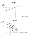
- Fig. 3 shows a curve which shows the volume flow through a pipeline (in m3 / sec) in relation to the production speed (in kg / hour). This curve basically applies to all pipe elements of the system and therefore also to the guide channels of suction fans and the like.
- V ⁇ 1 there is a suitable volume flow V ⁇ 1 at a certain production speed P1.
- the curve in FIG. 4 shows the pressure increase / volume flow characteristic of a suction fan for different rotational speeds.
- the pressure increase via a suction fan can easily be determined by means of two pressure sensors, of which a first pressure sensor is arranged directly upstream of the fan and a second pressure sensor is arranged immediately downstream of the fan.
- the first pressure sensor measures P1 and the second pressure sensor P2.
- a pressure difference ⁇ P1 has therefore been measured at a fan speed of n2.
- the speed of rotation or speed n is of course known to the computer, which specifies the target speed of the suction fan.
- FIGS. 5 and 6 show an example which is similar to the first part of the system of FIGS. 1 and 2, but in which the use of pressure difference measurements in the first and second suction fans 14 and 22 is shown.
- Figures 5 and 6 use the same reference numerals as Figures 1 and 2 to indicate items that are common to both embodiments. These common items therefore don't have to be described.
- FIGS. 5 and 6 show the use of two pressure sensors 89 and 89.1, which are respectively arranged upstream and downstream of the suction fan 14, and the use of two further pressure sensors 99 and 99.1, which in a corresponding manner with regard to the second suction fan 32 are attached.
- the computer 94 obtains the measured pressure values at the pressure sensors 89, 89.1 and 99, 99.1, from which the prevailing pressure differences are calculated in order to enable the volume flows to be set iteratively with regard to the characteristics of FIG. 4. If the volume flows are correct, the pressures in the critical areas 88, 90 and 92 must also be correct and the pressure sensors, which are provided as an option in this example, can be used to check the result of the iterative setting for the two suction fans . If this is not done, special care must be taken to ensure that the amount of air which optionally enters the pipe 12 via the branch pipe 16 is not excessive, since the pressure in the pipe in the region 88 may otherwise be too low could be.
- the amount of air flowing through the branch line 16 can be determined by suitable pressure measurements, for example in relation to the volume flow of a further fan (not shown) which is responsible for supplying the waste component along the line 16 or in relation to the pressure drop the opening where the branch line meets line 12. It is clear, of course, that changing the setting of one of the suction fans will also cause a change in the other suction fan. However, the directions and magnitudes of the commanded speed changes of the two fans can be easily predicted from the stored pressure difference / volume flow characteristics for the two fans.
- the same pressure difference measurement method can also be used for adjusting the rotational speeds of the fans of the autonomously functioning units in order to ensure the desired volume flow through these units.
Landscapes
- Engineering & Computer Science (AREA)
- Textile Engineering (AREA)
- Mechanical Engineering (AREA)
- Preliminary Treatment Of Fibers (AREA)
Applications Claiming Priority (4)
| Application Number | Priority Date | Filing Date | Title |
|---|---|---|---|
| DE19893919744 DE3919744A1 (de) | 1989-06-16 | 1989-06-16 | Transportluftregelung |
| DE3919744 | 1989-06-16 | ||
| DE3940524 | 1989-12-07 | ||
| DE19893940524 DE3940524A1 (de) | 1989-12-07 | 1989-12-07 | Transportluftregelung |
Publications (2)
| Publication Number | Publication Date |
|---|---|
| EP0402941A1 true EP0402941A1 (fr) | 1990-12-19 |
| EP0402941B1 EP0402941B1 (fr) | 1995-05-10 |
Family
ID=25882016
Family Applications (1)
| Application Number | Title | Priority Date | Filing Date |
|---|---|---|---|
| EP90111351A Expired - Lifetime EP0402941B1 (fr) | 1989-06-16 | 1990-06-15 | Réglage de l'air de transport |
Country Status (4)
| Country | Link |
|---|---|
| US (1) | US5143485A (fr) |
| EP (1) | EP0402941B1 (fr) |
| JP (1) | JPH0390631A (fr) |
| DE (1) | DE59009044D1 (fr) |
Cited By (2)
| Publication number | Priority date | Publication date | Assignee | Title |
|---|---|---|---|---|
| CH715422A1 (de) * | 2018-10-02 | 2020-04-15 | Rieter Ag Maschf | Faservorbereitung mit einer Abfolge von Maschinen. |
| EP3913119A1 (fr) * | 2020-05-22 | 2021-11-24 | Maschinenfabrik Rieter AG | Système de transport de sortie dans une préparation des fibres |
Families Citing this family (9)
| Publication number | Priority date | Publication date | Assignee | Title |
|---|---|---|---|---|
| DE19954258A1 (de) | 1999-11-11 | 2001-05-17 | Truetzschler Gmbh & Co Kg | Vorrichtung zur elektronischen Steuerung von Spinnereimaschinen, insbesondere Spinnereivorbereitungsmaschinen |
| EP1215312A1 (fr) * | 2000-12-18 | 2002-06-19 | Maschinenfabrik Rieter Ag | Techniques de mesure en ligne |
| JP4244145B2 (ja) * | 2002-03-27 | 2009-03-25 | 株式会社日清製粉グループ本社 | 粉粒体搬送システム |
| DE10305049B4 (de) * | 2003-02-07 | 2018-08-02 | Trützschler GmbH & Co Kommanditgesellschaft | Vorrichtung zum pneumatischen Speisen mindestens einer Spinnereivorbereitungsmaschine, z.B. Karde, Reiniger |
| US7524146B2 (en) * | 2006-11-30 | 2009-04-28 | William Jeffrey Peet | Pneumatic uneven flow factoring for particulate matter distribution system |
| EP2254818A1 (fr) * | 2008-01-28 | 2010-12-01 | Johann Haberl | Système de conduit tubulaire, son procédé de commande et d'utilisation |
| ES2998033T3 (en) * | 2010-03-04 | 2025-02-18 | Envac Ab | Waste emptying control |
| CH713861A1 (de) * | 2017-06-08 | 2018-12-14 | Rieter Ag Maschf | Produktionssteuerung in einer Putzerei. |
| CH714101A1 (de) * | 2017-08-30 | 2019-03-15 | Rieter Ag Maschf | Vorrichtung zur Regelung eines Faserflockenstromes in einem Reiniger. |
Citations (4)
| Publication number | Priority date | Publication date | Assignee | Title |
|---|---|---|---|---|
| EP0000033A2 (fr) * | 1977-06-09 | 1978-12-20 | Maschinenfabrik Rieter Ag | Dispositif pour éliminer des impuretés métalliques d'une conduite transporteuse de fibres textiles dans la préparation de filature |
| FR2433063A1 (fr) * | 1978-08-07 | 1980-03-07 | Truetzschler & Co | Procede et dispositif de regulation d'un dispositif pneumatique d'alimentation en flocons pour une machine textile |
| FR2573780A1 (fr) * | 1984-11-24 | 1986-05-30 | Truetzschler & Co | Installation pour l'alimentation pneumatique en fibre d'un nombre variable de cadres |
| EP0303023A1 (fr) * | 1987-08-12 | 1989-02-15 | Maschinenfabrik Rieter Ag | Système pour le traitement de fibres textiles et methode de commande d'un tel système |
Family Cites Families (12)
| Publication number | Priority date | Publication date | Assignee | Title |
|---|---|---|---|---|
| FR1230526A (fr) * | 1959-03-21 | 1960-09-16 | Siderurgie Fse Inst Rech | Dispositif de régulation automatique d'un distributeur de poudre sous pression |
| CH525971A (de) * | 1969-10-15 | 1972-07-31 | Rieter Ag Maschf | Verfahren zum Erzeugen eines gleichmässigen, kontinuierlichen Faserverbandes und Vorrichtung zur Durchführung des Verfahrens |
| FR2236758B1 (fr) * | 1973-07-02 | 1978-12-29 | Pechiney Aluminium | |
| CH599990A5 (fr) * | 1975-07-16 | 1978-06-15 | Rieter Ag Maschf | |
| JPS5948222B2 (ja) * | 1979-01-24 | 1984-11-24 | 住友金属工業株式会社 | スラリ−輸送方法 |
| US4404710A (en) * | 1981-05-29 | 1983-09-20 | Rando Machine Corporation | Apparatus for feeding fibers to carding machines and the like |
| DE3134180C2 (de) * | 1981-08-28 | 1983-11-24 | Waeschle Maschinenfabrik Gmbh, 7980 Ravensburg | Verfahren zur Dosierung von pneumatisch transportiertem Schüttgut |
| ATE32918T1 (de) * | 1984-08-28 | 1988-03-15 | Rieter Ag Maschf | Pneumatische transportanlage fuer faserflocken. |
| DE3435907A1 (de) * | 1984-09-29 | 1986-04-10 | AVT Anlagen- und Verfahrenstechnik GmbH, 7981 Vogt | Verfahren und einrichtung zum pneumatischen und hydraulischen transport von feststoffen durch rohrleitungen |
| ATE34190T1 (de) * | 1984-10-30 | 1988-05-15 | Rieter Ag Maschf | Transportkanal fuer faserflocken. |
| JPS6413306A (en) * | 1987-07-08 | 1989-01-18 | Shin Meiwa Ind Co Ltd | Conveyance device for refuse container |
| US5048761A (en) * | 1990-03-14 | 1991-09-17 | The Babcock & Wilcox Company | Pulverized coal flow monitor and control system and method |
-
1990
- 1990-06-11 US US07/536,210 patent/US5143485A/en not_active Expired - Fee Related
- 1990-06-15 JP JP2155591A patent/JPH0390631A/ja active Pending
- 1990-06-15 DE DE59009044T patent/DE59009044D1/de not_active Expired - Fee Related
- 1990-06-15 EP EP90111351A patent/EP0402941B1/fr not_active Expired - Lifetime
Patent Citations (4)
| Publication number | Priority date | Publication date | Assignee | Title |
|---|---|---|---|---|
| EP0000033A2 (fr) * | 1977-06-09 | 1978-12-20 | Maschinenfabrik Rieter Ag | Dispositif pour éliminer des impuretés métalliques d'une conduite transporteuse de fibres textiles dans la préparation de filature |
| FR2433063A1 (fr) * | 1978-08-07 | 1980-03-07 | Truetzschler & Co | Procede et dispositif de regulation d'un dispositif pneumatique d'alimentation en flocons pour une machine textile |
| FR2573780A1 (fr) * | 1984-11-24 | 1986-05-30 | Truetzschler & Co | Installation pour l'alimentation pneumatique en fibre d'un nombre variable de cadres |
| EP0303023A1 (fr) * | 1987-08-12 | 1989-02-15 | Maschinenfabrik Rieter Ag | Système pour le traitement de fibres textiles et methode de commande d'un tel système |
Cited By (4)
| Publication number | Priority date | Publication date | Assignee | Title |
|---|---|---|---|---|
| CH715422A1 (de) * | 2018-10-02 | 2020-04-15 | Rieter Ag Maschf | Faservorbereitung mit einer Abfolge von Maschinen. |
| EP3913119A1 (fr) * | 2020-05-22 | 2021-11-24 | Maschinenfabrik Rieter AG | Système de transport de sortie dans une préparation des fibres |
| CN113718380A (zh) * | 2020-05-22 | 2021-11-30 | 里特机械公司 | 纤维制备中的垃圾运输系统 |
| CN113718380B (zh) * | 2020-05-22 | 2025-11-14 | 里特机械公司 | 纤维制备中的垃圾运输系统 |
Also Published As
| Publication number | Publication date |
|---|---|
| DE59009044D1 (de) | 1995-06-14 |
| US5143485A (en) | 1992-09-01 |
| JPH0390631A (ja) | 1991-04-16 |
| EP0402941B1 (fr) | 1995-05-10 |
Similar Documents
| Publication | Publication Date | Title |
|---|---|---|
| EP0917828B1 (fr) | Procédé et dispositif de régulation de l'humidité de sortie du tabac | |
| EP0402941B1 (fr) | Réglage de l'air de transport | |
| EP3546625B1 (fr) | Dispositif d'alimentation pour une carde | |
| WO2014001867A1 (fr) | Procédé et dispositif pour réguler l'alimentation en fibres d'une cardeuse | |
| EP0810309B1 (fr) | Installation pour le traitement de fibres | |
| EP0475073B1 (fr) | Ligne de nettoyage | |
| EP3530781B1 (fr) | Dispositif d'alimentation d'une carde | |
| DE10122459A1 (de) | Vorrichtung an einer Karde, Reinigungsmaschine, Öffnungsmaschine o. dgl. für Fasermaterial | |
| DE10214389A1 (de) | Vorrichtung in der Spinnereivorbereitung zum Abscheiden der Transportluft beim Beschicken von Fasermaterial, z.B. Baumwolle o. dgl., zu einer Verarbeitungsmaschine | |
| DE2718146A1 (de) | Offen-end-spinnvorrichtung | |
| CH714844A1 (de) | Speisevorrichtung zu einer Karde. | |
| DE3916986A1 (de) | Verteiler zur speisung einer mehrzahl von schaechten | |
| DE2252081C3 (de) | Krempel zur Bearbeitung von Fasermaterial u.dgl., insbesondere Spinngut, mit zumindest einer Tambourwalze | |
| DE69518535T2 (de) | Kardenabfallüberwachung | |
| DE3940524A1 (de) | Transportluftregelung | |
| DE3919744A1 (de) | Transportluftregelung | |
| CH682921A5 (de) | Vorrichtung zum pneumatischen Speisen mindestens einer Faserverarbeitungsmaschine, z.B. Karde. | |
| EP0412446B1 (fr) | Procédé pour influencer le conditionnement des fibres traitées sur machine de filature | |
| EP1917388A1 (fr) | Systeme d'alimentation en flocons | |
| DE102005038405A1 (de) | Reinigungsvorrichtung | |
| CH714101A1 (de) | Vorrichtung zur Regelung eines Faserflockenstromes in einem Reiniger. | |
| EP0877106B1 (fr) | Procédé pour emplir une cheminée d'alimentation de flocons et cheminée d'alimentation | |
| CH714817A1 (de) | Vorrichtung zur Führung eines Vliesbandes in einer Bandbildungseinheit einer Karde. | |
| CH713868A1 (de) | Vorrichtung zum Austrag von Faserflocken aus einem Speicher. | |
| DE9017760U1 (de) | Vorrichtung zum Abscheiden von Fremdkörpern, insbesondere Schwerteilen wie Metall-, Holz-, Pappteilen, Steinen u.dgl., aus Baumwollfaserflocken in der Spinnereivorbereitung |
Legal Events
| Date | Code | Title | Description |
|---|---|---|---|
| PUAI | Public reference made under article 153(3) epc to a published international application that has entered the european phase |
Free format text: ORIGINAL CODE: 0009012 |
|
| AK | Designated contracting states |
Kind code of ref document: A1 Designated state(s): CH DE ES FR GB IT LI |
|
| 17P | Request for examination filed |
Effective date: 19910227 |
|
| 17Q | First examination report despatched |
Effective date: 19930903 |
|
| GRAA | (expected) grant |
Free format text: ORIGINAL CODE: 0009210 |
|
| AK | Designated contracting states |
Kind code of ref document: B1 Designated state(s): CH DE ES FR GB IT LI |
|
| PG25 | Lapsed in a contracting state [announced via postgrant information from national office to epo] |
Ref country code: IT Free format text: LAPSE BECAUSE OF FAILURE TO SUBMIT A TRANSLATION OF THE DESCRIPTION OR TO PAY THE FEE WITHIN THE PRE;WARNING: LAPSES OF ITALIAN PATENTS WITH EFFECTIVE DATE BEFORE 2007 MAY HAVE OCCURRED AT ANY TIME BEFORE 2007. THE CORRECT EFFECTIVE DATE MAY BE DIFFERENT FROM THE ONE RECORDED.SCRIBED TIME-LIMIT Effective date: 19950510 Ref country code: GB Effective date: 19950510 Ref country code: FR Effective date: 19950510 Ref country code: ES Free format text: THE PATENT HAS BEEN ANNULLED BY A DECISION OF A NATIONAL AUTHORITY Effective date: 19950510 |
|
| REF | Corresponds to: |
Ref document number: 59009044 Country of ref document: DE Date of ref document: 19950614 |
|
| PG25 | Lapsed in a contracting state [announced via postgrant information from national office to epo] |
Ref country code: LI Effective date: 19950630 Ref country code: CH Effective date: 19950630 |
|
| EN | Fr: translation not filed | ||
| GBV | Gb: ep patent (uk) treated as always having been void in accordance with gb section 77(7)/1977 [no translation filed] |
Effective date: 19950510 |
|
| REG | Reference to a national code |
Ref country code: CH Ref legal event code: PL |
|
| PG25 | Lapsed in a contracting state [announced via postgrant information from national office to epo] |
Ref country code: DE Effective date: 19960301 |
|
| PLBE | No opposition filed within time limit |
Free format text: ORIGINAL CODE: 0009261 |
|
| STAA | Information on the status of an ep patent application or granted ep patent |
Free format text: STATUS: NO OPPOSITION FILED WITHIN TIME LIMIT |
|
| 26N | No opposition filed |