EP0403094A2 - Optisches Rückstreumessgerät und optische Rückstreuvorrichtung - Google Patents
Optisches Rückstreumessgerät und optische Rückstreuvorrichtung Download PDFInfo
- Publication number
- EP0403094A2 EP0403094A2 EP90305662A EP90305662A EP0403094A2 EP 0403094 A2 EP0403094 A2 EP 0403094A2 EP 90305662 A EP90305662 A EP 90305662A EP 90305662 A EP90305662 A EP 90305662A EP 0403094 A2 EP0403094 A2 EP 0403094A2
- Authority
- EP
- European Patent Office
- Prior art keywords
- light
- signal
- measuring
- optical
- fiber
- Prior art date
- Legal status (The legal status is an assumption and is not a legal conclusion. Google has not performed a legal analysis and makes no representation as to the accuracy of the status listed.)
- Granted
Links
Images




Classifications
-
- G—PHYSICS
- G01—MEASURING; TESTING
- G01M—TESTING STATIC OR DYNAMIC BALANCE OF MACHINES OR STRUCTURES; TESTING OF STRUCTURES OR APPARATUS, NOT OTHERWISE PROVIDED FOR
- G01M11/00—Testing of optical apparatus; Testing structures by optical methods not otherwise provided for
- G01M11/30—Testing of optical devices, constituted by fibre optics or optical waveguides
- G01M11/31—Testing of optical devices, constituted by fibre optics or optical waveguides with a light emitter and a light receiver being disposed at the same side of a fibre or waveguide end-face, e.g. reflectometers
- G01M11/3172—Reflectometers detecting the back-scattered light in the frequency-domain, e.g. OFDR, FMCW, heterodyne detection
Definitions
- the present invention relates to a method of measuring backscattered light generated in an optical fiber by entering a measuring light signal into the fiber, and also relates to a device for the measuring.
- a conventional method of measuring the intensity of the backscattered light is the most effective way to determine the distribution of the optical transmission loss in the fiber, and is an indispensable art of searching for the point of a trouble in the fiber. However, since the intensity of the backscattered light coming rearward to the entering end of the optical fiber is very low, heightening the intensity of the light signal to be entered into the fiber, reducing the energy loss in an optical system quick averaging and so forth need to be done in order to improve the ratio of the backscattered light to noise in the measurement.
- FIG. 3 is a block diagram of the conventional method of measuring the intensity of the backscattered light by using a light pulse.
- FIGS. 4(a), 4(b), 4(c) and 4(d) are graphs showing the wave forms of signals at points a, b, c and d shown in FIG. 3
- FIG. 3 shows a pulse generator 1, a light source 2 such as a semiconductor laser diode, an optical directional coupler 3, the optical fiber under test 4, a optical receiver 5, an averaging circuit 6, and a display circuit 7.
- the pulse generator 1 produces a single pulse signal P whose repetition period T is conditioned as T > 2 l/v wherein l and v denote the length of the optical fiber 4 and the speed of the transmission of the entered light signal L in the fiber, respectively.
- the repetition p eriod T is longer than two times of the time which it takes for the light signal L to be transmitted through the optical fiber 4.
- the light source 2 emits the light signal L of optional wavelength.
- the optical directional coupler 3 functions so that the light signal L emitted from the light source 2 and modulated in intensity as shown in FIG.
- the optical receiver 5 receives the backscattered light LB from the coupler 3 and converts the light into an electric signal EB shown in FIG. 4(d).
- the averaging circuit 6 includes a high-speed A/D converter and a memory.
- the display circuit 7 is for showing a signal EA generated as a result of the averaging performed by the circuit 6.
- the light signal L modulated in intensity by the single pulse signal P is entered into the optical fiber 4 through the optical directional coupler 3, the light undergoes the Rayleigh scattering while being transmitted in the fiber, so that the backscattered light LB is generated.
- the backscattered light LB coming rearward to the entering end of the optical fiber 4 is taken out therefrom by the coupler 3 and then converted into electric signal EB by the optical receiver 5.
- the electric signal EB generated by the optical receiver 5 and corresponding to the intensity of the backscattered light LB is quantized by the high-speed A/D converter of the averaging circuit 6.
- a quantized signal sent out from the A/D converter is subjected to synchronous addition in the time region of the memory as the pulse signal P from the pulse generator is used as a trigger, so that the averaging is performed on the quantized signal.
- the intensities of averaged signals EA thus stored in the time region of the memory are sequentially shown by the display circuit 7 in such a manner that an x-axis indicates the length of the optical fiber 4.
- the distribution of the optical transmission loss in the optical fiber 4 in the longitudinal direction thereof can thus be indicated by the intensities shown by the display circuit 7.
- the measurement of the intensity of the backscattered light LB is so different, due to other backscattered light generated from the communication signal light in the optical communication system, the optical two-way communication system, a norepeater optical communication system or the like, that the distribution of the optical transmission loss in the optical fiber of the system cannot be monitored during the service thereof.
- FIG. 5 is a block diagram of another conventional method of measuring the backscattered light through such optical heterodyne detection.
- a light singal L10 of optical frequency f0 is emitted from a light source 2 and separated by an optical divider 8 so that a separated light signal L11 is sent to an acousto-optical modulator 9 for frequency modulation and another separated light signal L12 is sent to an optical combiner 10 for a local oscillation light signal.
- the light signal L11 applied as a measuring light signal to the acousto-optical modulator 9 is subjected to the frequency modulation by the acoustic optical effect of the unit, which is based on an electric sine-wave signal S of frequency ⁇ f, which is generated by a drive circuit 11.
- the light signal L11 is converted into a light signal of frequency f0 + ⁇ f.
- the frequency modulation based on the electric sine-wave signal S is restricted by a pulse signal P produced by a pulse genrator 1 to obtain a single pulse light signal L13 of frequency f0 + ⁇ f as a light signal for measuring the backscattered light L14.
- the single pulse light signal L13 is entered into the optical fiber 4 at the entering end thereof through an optical directional coupler 3.
- the bakcscattered light L14 of frequency f0 + ⁇ f which comes rearward to the entering end of the optical fiber 4 as a result of the entering of the light signal L13 into the fiber, is combined with the separated light signal L12 in the light combiner 10.
- a combined light signal L15 thus generated by the combiner 10 is subjected to the optical heterodyne detection in a optical receiver 5 so that a beat signal E0 of frequency ⁇ f is generated.
- the beat signal E0 is processed through a band-pass filter 12 so that the beat signal is removed of background noise light unnecessary for the meas urement.
- the beat signal E0 is then subjected to detection by an envelope detector 16.
- the output from the detector 16 is subjected to averaging by an averaging circuit 6.
- the output from the averaging circuit 6 is indiacted.
- the acousto-optical modulator 9 is provided to perform the frequency modulation for the optical heterodyne detection, the insertion loss is increased to about 10 dB. For that reason, the intensity of the measuring light signal L13 is lowered so that the intensity of the backscattered light L14 generated in the optical fiber 4 is also lowered. This is a problem.
- the acousto-optical modulator 9 is very expensive. Therefore, the cost of the equipment for the measurement is high. This is another problem. If the conventional method is applied to an optical communication system including an optical repeater which performs optical amplification, there is a problem that it is not easy to perform the automatic power control of the repeater, because the measuring light signal L13 has a pulse wave from.
- the present invention was made in order to solve the abovementioned problems.
- the measuring light signal from a light source is entered into an optical fiber at the entering end thereof so that the backscattered light is generated in the fiber.
- the backscattered light is taken out from the optical fiber at the entering end thereof and then measured.
- the method is characterized in that the measuring light signal oscillating continuously and subjected to frequency modulation at a predetermined period is entered into the optical fiber at the entering end thereof; the backscattered light generated in the fiber and the measuring light signal subjected to the frequency modulation are subjected to optical heterodyne detection; and a beat signal obtained through the detection is processed through a filter and then measured.
- the measuring light signal from the light source is entered into the optical fiber at the entering end thereof so that the backscattered light is generated in the fiber.
- the bakcscattered light is taken out from the optical fiber at the entering end thereof and then measured.
- the device is characterized by comprising a pulse generation means for producing a pulse at the predetermined period; a frequency modulation means for performing the frequency modulation on the measuring light signal from the light source in accordance with the predetermined period; an optical combination means by which the backscattered light generated when the measuring light signal which is a continuous-wave signal subjected to the frequency modulation is transmitted in the optical fiber is combined with the measuring light signal subjected to the frequency modulation; an optical heterodyne detection means for performing the optical heterodyne detection on light generated as a result of the combination; a filter for processing the beat signal obtained through the detection means; and an envelope detection means for taking out the envelope of a beat signal sent out from the filter.
- the measuring light signal oscillating continuously and subjected to the fre quency modulation at the predetermined period is entered into the optical fiber at the entering end thereof so that the backscattered light is generated in the fiber.
- the backscattered light and the measuring light signal not subjected to the frequency modulation are subjected to the optical heterodyne detection.
- the beat signal obtained through the detection is processed through the filter.
- the latter beat signal sent out from the filter is measured.
- the backscattered light can thus be measured with a low optical transmission loss, without affecting an optical repeater, as the optical fiber is in service.
- T of the frequency modulation is conditioned as T > 2l/v wherein l and v denote the length of the optical fiber and the speed of the transmission of the measuring light signal in the fiber, respectively, a frequency component whose frequency is f0-f1 wherein f0 and f1 denote the frequency of the measuring light signal not subjected to the frequency modulation, and that of the measuring light signal subjected to the frequency modulation, respectively, can be simply taken out from the former beat signal generated from both the measuring light signal not subjected to the frequency modulation and the measuring light signal subjected thereto.
- the frequency of the latter beat signal is set at f0-f1
- the signal can simply be removed of noise light by a filter whose central frequency is f0-f1.
- the frequency modulation means is for directly modulating the oscillation frequency of the light source, the frequency modulation can be simply performed.
- the frequency modulation means is for modulating the oscillation frequency of the light source through the use of an external modulator, the accuracy of the frequency in the frequency modulation can be made high.
- Embodiments of the present invention are hereafter described in detail with reference to FIGS. 1 and 2.
- One of the embodiments is a method of measuring backscattered light.
- the other of the embodiments is a device for measuring the backscattered light. Units equivalent to those described for the above-mentioned conventional methods are denoted by the same reference symbols as the latter and not described in detail, hereinafter.
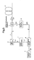
- FIG. 1 shows a band-pass filter 12, a light source 13 such as a DFB laser unit, a frequency modulation circuit 14, an optical combiner 15, and an envelope detector 16.
- the light source 13 has a narrow spectrum width.
- the frequency modulation circuit 14 is for performing such frequency modulation as to make a predetermined optical frequency difference in the light source 13.
- the optical combiner 15 functions so that measuring light signals L0 and L1 emitted from the light source 13 are combined with backscattered light rays L0B and L1B generated in an optical fiber 4.
- the band-pass filter 12 processes a beat signal E0 obtained through optical heterodyne detection by a optical receiver 5, and has an appropriate pass band whose central frequency is an electric intermediate frequency equal to a beat frequency and the predetermined optical frequency difference f0-f1 made by the frequency modulation circuit 14.
- the envelope detector 16 performs envelope detection on a beat signal E1 obtained through the band-pass filter 12.
- a pulse signal P acts in the frequency modulation circuit 14 so that the output light signals L0 and L1 from the light source 13 have optical frequencies f0 and f1 as shown in FIGS. 2(b1) and 2(b2).
- the frequency modulation circuit 14 directly performs the frequency modulation on the light source 13, or performs the modulation through the use of an external mod ulator based on an electrochemical effect or the like, so that the light signals L0 and L1 oscillate with the predetermined optical frequency difference f0-f1.
- the output light signal L0 emitted from the light source 13 when the frequency modulation is not performed on the light source has the optical frequency f0.
- the other output light signal L1 emitted from the light source 13 when the frequency modulation is performed on the light source through the use of the pulse signal P has the other optical frequency f1.
- the light signals L0 and L1 different from each other in optical frequency because of the frequency modulation and generated at different time points are hereinafter referred to as the reference light signal L0 and the frequency shifted light signal L1, respectively.
- the frequency modulation is performed through the use of the pulse signal P having a repetition period T and a pulse time width W and shown in FIG. 2(a), as well as the pulse signal P in the conventional method described above with reference to FIG. 3. For that reason, the modulation light signal L1 is emitted from the light source 13 for a modulation period W. The non-modulation light signal L0 is emitted from the light source 13 for a seference period T-W.
- the emission of the seference light signal L0 from the light source 13 is kept while the frequency shifted light signal L1 serving as a measuring light signal for generating the backscattered light to be measured is being transmitted in the optical fiber 4 for a period of 2l/v wherein l and v denote the length of the fiber and the speed of the transmission, respectively.
- Each of the seference signal L0 and the furquency shifted signal L1 is divided by an optically directive coupler 3 so that a divided portion of each of the signals is entered as a measuring light signal into the optical fiber 4 and the other divided portion of each of the signals is entered, as a local oscillation light signal for the optical heterodyne detection, into the optical combiner 15.
- the refrence light signal L0 and the frequency shifted light signal L1 entered into the fiber 4 act to generate the backscattered light rays L0B and L1B in the fiber, respectively.
- the backscattered light rays L0B and L1B are taken out from the optical fiber 4 by the optically directive coupler 3, applied to the optical combiner 15, and combined with the reference light signal L0 entered as the local oscillation light signal into the combiner.
- a combined light signal L5 obtained from the combiner 15 as a result of the combination is subjected to the optical heterodyne detection based on the square-law detection characteristic of the light receiver 5, so that the beat signal E0 corresponding to the frequency difference f0-f1 is obtained.
- the frequency shifted light signal L1 is a local oscillation light signal and the reference light signal L0 is a measuring light signal in a case.
- an averaging circuit 6 does not perform averaging, synchronously with the wave form of the pulse signal P from a pulse generator 1, so that the averaging circuit sends out no output signal to a display circuit 7.
- a frequency component f0-f1 of the beat signal E0 generated from both the backscattered light rays L1B based on the frequency shifted light signal L1 and the reference light signal L0 serving as the local oscillation light signal is extracted as the beat signal E1 by the band-pass filter 12, and then subjected to the envelope detection by the envelope detector 16 as shown in FIG. 2(d).
- the change in the intensity of the output signal from the detector 16 with the lapse of the time is observed so that the change is indicated by the display circuit 7.
- the light sources need to be controlled to always keep the frequency component f0-f1 of the beat signal E0 at a constant frequency despite external conditions such as temperature. Since only one light source 13 is used in the embodiments of the present invention, an automatic frequency control circuit is not required. Since the continuous light subjected to the frequency modulation is used as the measuring light signal in the embodiments, the present invention can be applied for a practical use without affecting automatic power control for the gain control of an optical amplifier.
Landscapes
- Physics & Mathematics (AREA)
- Optics & Photonics (AREA)
- Chemical & Material Sciences (AREA)
- Analytical Chemistry (AREA)
- General Physics & Mathematics (AREA)
- Testing Of Optical Devices Or Fibers (AREA)
- Investigating Or Analysing Materials By Optical Means (AREA)
Applications Claiming Priority (2)
| Application Number | Priority Date | Filing Date | Title |
|---|---|---|---|
| JP1146897A JP2515018B2 (ja) | 1989-06-12 | 1989-06-12 | 後方散乱光測定方式及びその装置 |
| JP146897/89 | 1989-06-12 |
Publications (3)
| Publication Number | Publication Date |
|---|---|
| EP0403094A2 true EP0403094A2 (de) | 1990-12-19 |
| EP0403094A3 EP0403094A3 (de) | 1991-11-13 |
| EP0403094B1 EP0403094B1 (de) | 1994-09-07 |
Family
ID=15418048
Family Applications (1)
| Application Number | Title | Priority Date | Filing Date |
|---|---|---|---|
| EP19900305662 Expired - Lifetime EP0403094B1 (de) | 1989-06-12 | 1990-05-24 | Optisches Rückstreumessgerät und optische Rückstreuvorrichtung |
Country Status (2)
| Country | Link |
|---|---|
| EP (1) | EP0403094B1 (de) |
| JP (1) | JP2515018B2 (de) |
Cited By (3)
| Publication number | Priority date | Publication date | Assignee | Title |
|---|---|---|---|---|
| AU617913B2 (en) * | 1988-12-06 | 1991-12-05 | British Telecommunications Public Limited Company | Loss detection |
| BE1005212A3 (nl) * | 1990-09-28 | 1993-05-25 | Ando Electric | Apparaat voor het testen van optische vezel door gebruik te maken van detector die virtueel verbreed dynamisch bereik heeft. |
| WO2002086439A3 (en) * | 2001-04-23 | 2003-12-04 | Systems And Processes Engineer | Method and system for measuring optical scattering characteristics |
Family Cites Families (5)
| Publication number | Priority date | Publication date | Assignee | Title |
|---|---|---|---|---|
| JPS55125427A (en) * | 1979-03-23 | 1980-09-27 | Kokusai Denshin Denwa Co Ltd <Kdd> | Method of measuring breaking position of optical |
| GB2179733B (en) * | 1985-08-29 | 1989-08-09 | Stc Plc | Plural wavelength optical fibre reflectometer |
| DE3609371A1 (de) * | 1986-03-20 | 1987-09-24 | Philips Patentverwaltung | Optisches zeitbereichsreflektometer mit heterodyn-empfang |
| JPS63314437A (ja) * | 1987-06-18 | 1988-12-22 | Yokogawa Electric Corp | 光ファイバ試験装置 |
| JP2676045B2 (ja) * | 1988-06-17 | 1997-11-12 | 日本電信電話株式会社 | 光パルス試験器 |
-
1989
- 1989-06-12 JP JP1146897A patent/JP2515018B2/ja not_active Expired - Fee Related
-
1990
- 1990-05-24 EP EP19900305662 patent/EP0403094B1/de not_active Expired - Lifetime
Cited By (4)
| Publication number | Priority date | Publication date | Assignee | Title |
|---|---|---|---|---|
| AU617913B2 (en) * | 1988-12-06 | 1991-12-05 | British Telecommunications Public Limited Company | Loss detection |
| BE1005212A3 (nl) * | 1990-09-28 | 1993-05-25 | Ando Electric | Apparaat voor het testen van optische vezel door gebruik te maken van detector die virtueel verbreed dynamisch bereik heeft. |
| WO2002086439A3 (en) * | 2001-04-23 | 2003-12-04 | Systems And Processes Engineer | Method and system for measuring optical scattering characteristics |
| US7057714B2 (en) | 2001-04-23 | 2006-06-06 | Systems And Processes Engineering Corporation | Method and system for measuring optical scattering characteristics |
Also Published As
| Publication number | Publication date |
|---|---|
| JP2515018B2 (ja) | 1996-07-10 |
| EP0403094A3 (de) | 1991-11-13 |
| JPH0313835A (ja) | 1991-01-22 |
| EP0403094B1 (de) | 1994-09-07 |
Similar Documents
| Publication | Publication Date | Title |
|---|---|---|
| EP0147251B1 (de) | Verfahren und Vorrichtung zur Messung des Dispersionskoeffizienten | |
| US11402295B2 (en) | Optical fiber loss measurement device and optical fiber loss measurement method | |
| JPH01291141A (ja) | 光ファイバ分散特性測定方式 | |
| GB2310096A (en) | Multiwavelength optical amplifier evaluation apparatus | |
| US20240426640A1 (en) | Integrated system for optical fiber sensing and communication through sharing co-frequency resources | |
| US5390017A (en) | Optical network analyzer for measuring the amplitude characteristics and group delay time dispersion characteristics of an optical circuit device | |
| JP3237745B2 (ja) | 歪・温度分布測定方法およびその測定装置 | |
| US6067149A (en) | Dispersion-map measurements of optical fibers | |
| EP0403094B1 (de) | Optisches Rückstreumessgerät und optische Rückstreuvorrichtung | |
| CN111044486A (zh) | 一种高速太赫兹相干测量装置及方法 | |
| CN112104415B (zh) | 一种采用edfa放大装置检测瑞利散射信号强度的系统 | |
| JP2023131864A (ja) | 光ファイバセンサ及びブリルアン周波数シフト測定方法 | |
| CN114485748A (zh) | 一种多参量分布式光纤传感的方法和系统 | |
| JP3236661B2 (ja) | 光パルス試験器 | |
| JPH05322699A (ja) | 高距離分解能光伝送路測定装置 | |
| JP3243774B2 (ja) | 光周波数領域反射測定方法及び測定回路 | |
| JPS62159928A (ja) | 光受信系の周波数応答測定装置 | |
| CN223596989U (zh) | 分布式光纤声波传感系统及光纤传感设备 | |
| JPH0540075A (ja) | 光パルス試験器 | |
| CN222799919U (zh) | 基于不等臂干涉仪的锁相装置及系统 | |
| JPH08184502A (ja) | 光波形測定装置 | |
| JPH06331495A (ja) | 零分散波長測定装置および零分散波長測定方法 | |
| JP3354630B2 (ja) | 光伝送特性測定装置 | |
| JPH02281122A (ja) | 光ファイバの波長分散分布測定装置 | |
| RU1793213C (ru) | Способ контрол состо ни длинномерного объекта и устройство дл его осуществлени |
Legal Events
| Date | Code | Title | Description |
|---|---|---|---|
| PUAI | Public reference made under article 153(3) epc to a published international application that has entered the european phase |
Free format text: ORIGINAL CODE: 0009012 |
|
| AK | Designated contracting states |
Kind code of ref document: A2 Designated state(s): FR GB |
|
| PUAL | Search report despatched |
Free format text: ORIGINAL CODE: 0009013 |
|
| AK | Designated contracting states |
Kind code of ref document: A3 Designated state(s): FR GB |
|
| 17P | Request for examination filed |
Effective date: 19911211 |
|
| 17Q | First examination report despatched |
Effective date: 19930129 |
|
| GRAA | (expected) grant |
Free format text: ORIGINAL CODE: 0009210 |
|
| AK | Designated contracting states |
Kind code of ref document: B1 Designated state(s): FR GB |
|
| ET | Fr: translation filed | ||
| PLBE | No opposition filed within time limit |
Free format text: ORIGINAL CODE: 0009261 |
|
| STAA | Information on the status of an ep patent application or granted ep patent |
Free format text: STATUS: NO OPPOSITION FILED WITHIN TIME LIMIT |
|
| 26N | No opposition filed | ||
| REG | Reference to a national code |
Ref country code: GB Ref legal event code: 732E |
|
| REG | Reference to a national code |
Ref country code: FR Ref legal event code: TP |
|
| REG | Reference to a national code |
Ref country code: GB Ref legal event code: IF02 |
|
| REG | Reference to a national code |
Ref country code: GB Ref legal event code: 732E |
|
| REG | Reference to a national code |
Ref country code: FR Ref legal event code: TP Ref country code: FR Ref legal event code: CD |
|
| PGFP | Annual fee paid to national office [announced via postgrant information from national office to epo] |
Ref country code: GB Payment date: 20080522 Year of fee payment: 19 |
|
| GBPC | Gb: european patent ceased through non-payment of renewal fee |
Effective date: 20090524 |
|
| REG | Reference to a national code |
Ref country code: FR Ref legal event code: ST Effective date: 20100129 |
|
| PG25 | Lapsed in a contracting state [announced via postgrant information from national office to epo] |
Ref country code: FR Free format text: LAPSE BECAUSE OF NON-PAYMENT OF DUE FEES Effective date: 20090602 |
|
| PGFP | Annual fee paid to national office [announced via postgrant information from national office to epo] |
Ref country code: FR Payment date: 20080425 Year of fee payment: 19 |
|
| PG25 | Lapsed in a contracting state [announced via postgrant information from national office to epo] |
Ref country code: GB Free format text: LAPSE BECAUSE OF NON-PAYMENT OF DUE FEES Effective date: 20090524 |