EP0403255A2 - Ölniveauregelventilanordnung für Automobile - Google Patents
Ölniveauregelventilanordnung für Automobile Download PDFInfo
- Publication number
- EP0403255A2 EP0403255A2 EP90306445A EP90306445A EP0403255A2 EP 0403255 A2 EP0403255 A2 EP 0403255A2 EP 90306445 A EP90306445 A EP 90306445A EP 90306445 A EP90306445 A EP 90306445A EP 0403255 A2 EP0403255 A2 EP 0403255A2
- Authority
- EP
- European Patent Office
- Prior art keywords
- leg
- cover member
- base
- level control
- control valve
- Prior art date
- Legal status (The legal status is an assumption and is not a legal conclusion. Google has not performed a legal analysis and makes no representation as to the accuracy of the status listed.)
- Withdrawn
Links
- 230000005540 biological transmission Effects 0.000 claims description 30
- 238000005452 bending Methods 0.000 claims description 3
- 239000012530 fluid Substances 0.000 abstract description 4
- 238000009434 installation Methods 0.000 description 5
- 239000000463 material Substances 0.000 description 4
- 238000005266 casting Methods 0.000 description 3
- 230000004048 modification Effects 0.000 description 2
- 238000012986 modification Methods 0.000 description 2
- 229910001220 stainless steel Inorganic materials 0.000 description 2
- 239000010935 stainless steel Substances 0.000 description 2
- 206010021580 Inadequate lubrication Diseases 0.000 description 1
- 230000006835 compression Effects 0.000 description 1
- 238000007906 compression Methods 0.000 description 1
- 230000008878 coupling Effects 0.000 description 1
- 238000010168 coupling process Methods 0.000 description 1
- 238000005859 coupling reaction Methods 0.000 description 1
- 230000007423 decrease Effects 0.000 description 1
- 230000002939 deleterious effect Effects 0.000 description 1
- 238000004519 manufacturing process Methods 0.000 description 1
- 230000036316 preload Effects 0.000 description 1
- 230000001105 regulatory effect Effects 0.000 description 1
Images


Classifications
-
- F—MECHANICAL ENGINEERING; LIGHTING; HEATING; WEAPONS; BLASTING
- F16—ENGINEERING ELEMENTS AND UNITS; GENERAL MEASURES FOR PRODUCING AND MAINTAINING EFFECTIVE FUNCTIONING OF MACHINES OR INSTALLATIONS; THERMAL INSULATION IN GENERAL
- F16H—GEARING
- F16H57/00—General details of gearing
- F16H57/04—Features relating to lubrication or cooling or heating
- F16H57/0447—Control of lubricant levels, e.g. lubricant level control dependent on temperature
-
- F—MECHANICAL ENGINEERING; LIGHTING; HEATING; WEAPONS; BLASTING
- F16—ENGINEERING ELEMENTS AND UNITS; GENERAL MEASURES FOR PRODUCING AND MAINTAINING EFFECTIVE FUNCTIONING OF MACHINES OR INSTALLATIONS; THERMAL INSULATION IN GENERAL
- F16K—VALVES; TAPS; COCKS; ACTUATING-FLOATS; DEVICES FOR VENTING OR AERATING
- F16K31/00—Actuating devices; Operating means; Releasing devices
- F16K31/002—Actuating devices; Operating means; Releasing devices actuated by temperature variation
-
- F—MECHANICAL ENGINEERING; LIGHTING; HEATING; WEAPONS; BLASTING
- F16—ENGINEERING ELEMENTS AND UNITS; GENERAL MEASURES FOR PRODUCING AND MAINTAINING EFFECTIVE FUNCTIONING OF MACHINES OR INSTALLATIONS; THERMAL INSULATION IN GENERAL
- F16N—LUBRICATING
- F16N19/00—Lubricant containers for use in lubricators or lubrication systems
-
- G—PHYSICS
- G05—CONTROLLING; REGULATING
- G05D—SYSTEMS FOR CONTROLLING OR REGULATING NON-ELECTRIC VARIABLES
- G05D23/00—Control of temperature
- G05D23/01—Control of temperature without auxiliary power
- G05D23/02—Control of temperature without auxiliary power with sensing element expanding and contracting in response to changes of temperature
- G05D23/08—Control of temperature without auxiliary power with sensing element expanding and contracting in response to changes of temperature with bimetallic element
-
- G—PHYSICS
- G05—CONTROLLING; REGULATING
- G05D—SYSTEMS FOR CONTROLLING OR REGULATING NON-ELECTRIC VARIABLES
- G05D9/00—Level control, e.g. controlling quantity of material stored in vessel
- G05D9/02—Level control, e.g. controlling quantity of material stored in vessel without auxiliary power
-
- F—MECHANICAL ENGINEERING; LIGHTING; HEATING; WEAPONS; BLASTING
- F16—ENGINEERING ELEMENTS AND UNITS; GENERAL MEASURES FOR PRODUCING AND MAINTAINING EFFECTIVE FUNCTIONING OF MACHINES OR INSTALLATIONS; THERMAL INSULATION IN GENERAL
- F16H—GEARING
- F16H57/00—General details of gearing
- F16H57/04—Features relating to lubrication or cooling or heating
- F16H57/0409—Features relating to lubrication or cooling or heating characterised by increasing efficiency, e.g. by reducing splash losses
-
- F—MECHANICAL ENGINEERING; LIGHTING; HEATING; WEAPONS; BLASTING
- F16—ENGINEERING ELEMENTS AND UNITS; GENERAL MEASURES FOR PRODUCING AND MAINTAINING EFFECTIVE FUNCTIONING OF MACHINES OR INSTALLATIONS; THERMAL INSULATION IN GENERAL
- F16H—GEARING
- F16H57/00—General details of gearing
- F16H57/04—Features relating to lubrication or cooling or heating
- F16H57/0447—Control of lubricant levels, e.g. lubricant level control dependent on temperature
- F16H57/0449—Sensors or indicators for controlling the fluid level
-
- F—MECHANICAL ENGINEERING; LIGHTING; HEATING; WEAPONS; BLASTING
- F16—ENGINEERING ELEMENTS AND UNITS; GENERAL MEASURES FOR PRODUCING AND MAINTAINING EFFECTIVE FUNCTIONING OF MACHINES OR INSTALLATIONS; THERMAL INSULATION IN GENERAL
- F16H—GEARING
- F16H57/00—General details of gearing
- F16H57/04—Features relating to lubrication or cooling or heating
- F16H57/045—Lubricant storage reservoirs, e.g. reservoirs in addition to a gear sump for collecting lubricant in the upper part of a gear case
Definitions
- This application relates generally to a fluid control valve and more particularly to a temperature responsive valve for use with transmission oil reservoir.
- Hydraulic pressure systems as used in motor vehicles require a supply of transmission fluid and maintaining an adequate oil level in the transmission oil pan at all operating temperatures is essential for trouble free transmission performance.
- the oil pan serves as a sump to provide the necessary supply, however, in front wheel drive vehicles the transmission oil pan is too shallow to hold a suitable quantity.
- the problem is exacerbated by the fact that the volume of the oil used expands in the order of thirty-eight percent at elevated temperatures.
- the problem has been dealt with by employing an auxiliary reservoir, for example, in the side of the transmission case cover.
- the fluid level in the auxiliary reservoir is controlled by a thermostatic element which controls the opening and closing of a cover plate in the transmission housing in response to the temperature of the oil in the auxiliary reservoir. As the temperature of the oil in the reservoir decreases the cover plate opens allowing the oil to drain into the lower sump or oil pan to maintain the desired oil level.
- thermostatically controlled valve which will consistently provide desired oil level control in an automotive transmission oil pan.
- Another object is the provision of such a control which is inexpensive and is more easily installed than conventional devices.
- Yet another object is the provision of a control valve which is simple yet one which is reliable and consistent as used from one transmission to another.
- a valve assembly comprises an elongated base member having an aperture formed therein and having upstanding posts on either end of the aperture.
- a cover having post receiving apertures is slidingly received on the posts and is adapted to move from a position closing the aperture to a position in which the aperture is open.
- a thermostatic element in the form of an elongated strip has a generally V-shaped force imparting portion intermediate its ends mounted on the base with the force imparting portion intermediate its ends mounted on the base with the force imparting portion aligned with the cover.
- One end of the strip is captured by taps extending from one end of the base while the other end of the strip is captured by a bracket formed on the other end of the base. The position of the bracket is adjustable by bending a pair of legs connected to a transversely extending stop member until a desired force is imparted to the cover at a selected temperature.
- a generally U-shaped strip of thermostatic material has a first end mounted on one of a pair of post members extending upwardly from the base plate and has a second, opposite end biased against the cover plate which is slidably mounted between the post members.
- the cover plate and the thermostatic strip are formed with curved surfaces to produce a sliding point contact to enhance consistent modulation.
- the first end includes a portion of the bight of the U-shaped configuration with an aperture formed in the bight portion and another in the distal end adapted to lockingly receive the one post member through both apertures in a calibrated position.
- Slit stud members also project upwardly from the base plate and are adapted to be received in bores provided on an automotive transmission body casting.
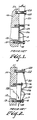
- a broken away portion of a transmission case cover 10 is shown having a drain passage 12 leading to an auxiliary reservoir.
- a conventional control for providing an adequate supply of oil in the sump positioned below the drain passage comprises a cover plate 14 disposed over the passage 12 slidably mounted on pins 16, 18 so that the cover can move between a closed position as shown in Fig. 1 (when the vehicle is not in operation) and an opened position shown in Fig. 2.
- a thermostatic element 20 in the form of an elongated strip having pin receiving slots at its opposite ends is mounted on pins 18 and 22 and captured there by the busings 17 and 23. Element 20 is formed intermediate its ends with a generally V-shaped force imparting portion 24 having apex 26 in engagement with cover plate 14.
- Element 20 is mounted on case cover 10 by inserting pins 18 and 22 through respective slot and hole in element 20 with pin 18 also inserted through a slot in cover plate 14 and then driving the pins into respective bores 19, 21 in the transmission case cover in an interference fit to a selected dimension "d" as shown in Fig. 1 at a selected temperature, e.g., normal room temperature.
- oil circulates through the transmission system with the oil pushing the cover plate toward the open position against the bias of the thermostatic element.
- Element 20 is a simple stamped part and its precise configuration tends to vary slightly from one part to another, however, the dimension "d" is the same for all the controls. This has resulted in a variance of up to 30% from the designed force level at a given temperature. In order to avoid the possibility of having inadequate lubrication which would result when there is insufficient oil in the sump there has been a tendency to increase the amount of oil so that in the worst case of a variance from the designed force level there is an adequate supply. However, this causes problems in units in which the control does not vary significantly from the designed level resulting in too much oil in the sump causing frothing with concomitant deleterious effects on the performance of the transmission due to the presence of air in the hydraulic system.
- control valve made in accordance with the invention overcomes this problem by providing a unit which is individually calibrated to a desired force exerted on the cover at a selected temperature with the calibrated unit then installed on the transmission case cover so that the performance of the control is consistent from one transmission to another.
- a base 32 formed of suitable material such as a 400 series stainless steel is generally in the form of an elongated rectangle having downwardly depending tangs 34, 36 at respective opposite ends thereof.
- Base 32 is formed with an aperture 38 therethrough which generally matches that of passage 12 of the transmission case cover 10 with tangs 34, 36 respectfully received in bores 19, 21 formed in housing 10.
- Base 32 is preferably formed with ribs 40, 42 depending therefrom along the length of aperture 38 to enhance the rigidity of the base.
- First and second posts 44, 46 extend upwardly from base 32 and are slidingly received through respective apertures 48, 50 formed in a cover 52.
- Cover 52 is slidingly movable on posts 44, 46 in a manner similar to cover 14's movability on pins 16, 18 in Figs. 1 and 2.
- Thermostatic element 56 is configured similar to element 20 shown in Figs. 1 and 2 having a generally V-shaped force imparting portion 58 and apex 60 which is adapted to place a force on cover 52.
- the opposite ends of element 56 have been modified as will be explained below.
- end 62 of element 56 has a reduced width so that it is captured under laterally extending tabs 64, 66 which are formed on respective posts 68, 70 extending upwardly from base 32 at one end thereof.
- End 62 is also recessed at 72, in any suitable configuration as in the portion of a circle as shown, in order to provide access for a tool generally in alignment with the tang (see arrow 74 in Fig. 4) to facilitate installation of valve 30 on a transmission housing.
- the opposite end of element 56 is formed with two spaced fingers extending generally in the direction of the length of element 56.
- End 80 of base 32 is formed into a bracket with first and second legs 82, 84 extending upwardly and then back along the length of element 56 and joined together by transversely extending stop element 86.
- a downwardly depending generally inverted T-shaped member 88 extends from element 86 and has laterally extending tabs 90, 92 formed at its lower end. Fingers 76, 78 are respectively received on either side of member 88 with transversely extending element 86 limiting upward movement of element 56 and tabs 90, 92 limiting downward movement thereof.
- Fingers 76, 78 are cut away at 94 and 96 respectively in a manner similar to cut out portion 72 on the opposite end of element 56 to provide access for a tool to facilitate installation of the valve on a transmission case cover. It will be seen that the tangs 34 and 36 can be conveniently driven into bores 19 and 21 of case cover 10 by a tool placed directly in line with the tangs.
- Valve 30 is calibrated by placing a force measuring gauge in engagement with the underside of cover 52 aligned generally with apex 60 of element 56, and with end 62 of element 56 received under tabs 64, 66 and fingers 76, 78 received under transversely extending stop element 86.
- bracket 80 is bent in a counter clockwise direction as seen in the Figure until the selected force for a given temperature is obtained on the gauge. When this selected or calibrated force is obtained the valve is ready for installation.
- Aperture 96 shown in dashed lines in Fig. 3 may be provided as a pilot hole to facilitate manufacture of the valve.
- Aperture 98 also shown in dashed lines is preferably provided to allow a limited amount of oil to pass through from the auxiliary reservoir to improve heat coupling of element 56 with the oil in the auxiliary reservoir.
- Post 46 is preferably provided with a transversely extending tab 100 at its distal free end to limit the outward movement of cover 52.
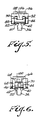
- a valve assembly 100 comprising a molded base 102 formed of suitable plastic material having a pair of post members 104, 106 extending upwardly therefrom.
- the first post member 104 serves as a mounting member for a thermostat element and, along with second post member 106, as a cover plate guide, as noted below.
- a generally U-shaped thermostatic element 108 having a first leg 108.1, a bight 108.2 and a second leg 108.3 is mounted on post member 104 by a first aperture 110 formed in the bight portion 108.2 of the U-shaped element 108 and a second aperture 112 formed in the distal end portion of leg 108.1 with the post member received through both apertures.
- Suitable teeth 114, 116 are formed adjacent the apertures and are adapted to bite or dig into the post member to maintain element in its selected position.
- first leg 108.1 is compressed slightly (toward the bight 108.2 of the U-shaped configuration).
- the leg is released to spring out biting into the post to stabilize the position of the element on the post member.
- a cover plate 120 formed of stainless steel or other suitable material, has slots 122, 124 formed at two opposite ends to accommodate post members 104, 106 respectively and is disposed on base 102 and adapted to move up and down along the post members. Cover 120 fits over aperture 126 formed in base 102 and is adapted to essentially close the aperture when it is in contact with the base 102.
- Cover 120 preferably is formed with a transversely extending curved protrusion 128, for example, a generally cylindrical portion having a first longitudinal axis extending in a direction across the width of the cover member which cooperates with a longitudinally extending curved portion 108.4, for example, a generally cylindrical portion having a second longitudinal axis along the length of the strip at a right angle with the first longitudinal axis formed on end 108.3 of the thermostatic element so that a sliding point contact is obtained between the thermostat element and the cover.
- Base 102 is also preferably formed with split stud members 130 extending upwardly from two opposite ends of the base which are adapted to be received in an interference fit in bores 132 of an automotive transmission casting 134.
- the thermostat element 108 is calibrated to place a predetermined preload on cover plate 120 covering the oil drain cavity in the transmission casting 134. As the oil temperature increases, its volume expands and the oil level in the reservoir increases. This increases the pressure on cover plate 120. Due to the temperature increase thermostat element 108 exerts pressure on cover plate 120 in the opposite direction to thereby modulate the opening to allow the oil to drain at a required rate to maintain a desired oil level in the sump.
- Figs. 9 and 10 show a slightly modified assembly.
- Thermostat element 208 having opposite ends 208.1 and 208.3 with bight 208.3 connecting the two legs of the generally U-shaped element is shown with the distal free portion of end 208.2 formed into a laterally extending curved or generally cylindrical configuration 208.4 which cooperates with a curved or generally cylindrical portion 228 in base 220 extending longitudinally at a right angle relative to the transverse extension of curved portion 208.4 to obtain a sliding point contact between the thermostat element and the cover plate.
- Aperture 210, formed in bight 208.3 is shown with teeth 214, however, aperture 212 is generally circular so that when the calibrated position is reached and the compression on leg 208.1 is released the leg will spring out with two points on the perimeter of the aperture biting into corners of the rectangular post 204 to stabilize the position of element 208 on the post.
- Bight 208.2 is shown with longitudinally extending flanges 208.5 to provide improved rigidity for transmitting force to the cover plate.
- the structure of the assembly is essentially the same as that shown in Figs. 7 and 8 and need not be redescribed.
- thermostatic valve is provided by the invention which is calibratable prior to installation to a specific force level and then easily installed on a transmission case cover to permit improved performance thereof.
- the invention permits using the proper quantity of oil because of the improved consistency of the operation of the valve, a typical calibrated force for one type of transmission is 1.4 ounces and it has been found that providing the controls to within ten percent of the desired force level is readily achievable.
Landscapes
- Engineering & Computer Science (AREA)
- General Engineering & Computer Science (AREA)
- Mechanical Engineering (AREA)
- Physics & Mathematics (AREA)
- General Physics & Mathematics (AREA)
- Automation & Control Theory (AREA)
- General Details Of Gearings (AREA)
- Temperature-Responsive Valves (AREA)
- Transmission Devices (AREA)
Applications Claiming Priority (2)
| Application Number | Priority Date | Filing Date | Title |
|---|---|---|---|
| US366904 | 1989-06-14 | ||
| US07/366,904 US4921165A (en) | 1989-06-14 | 1989-06-14 | Automotive oil level control valve apparatus |
Publications (2)
| Publication Number | Publication Date |
|---|---|
| EP0403255A2 true EP0403255A2 (de) | 1990-12-19 |
| EP0403255A3 EP0403255A3 (de) | 1991-07-10 |
Family
ID=23445082
Family Applications (1)
| Application Number | Title | Priority Date | Filing Date |
|---|---|---|---|
| EP19900306445 Withdrawn EP0403255A3 (de) | 1989-06-14 | 1990-06-13 | Ölniveauregelventilanordnung für Automobile |
Country Status (3)
| Country | Link |
|---|---|
| US (1) | US4921165A (de) |
| EP (1) | EP0403255A3 (de) |
| JP (1) | JPH0356780A (de) |
Families Citing this family (6)
| Publication number | Priority date | Publication date | Assignee | Title |
|---|---|---|---|---|
| US5209399A (en) * | 1992-06-11 | 1993-05-11 | Texas Instruments Incorporated | Automotive oil level control valve apparatus |
| DE19644738A1 (de) * | 1996-10-28 | 1998-04-30 | Zahnradfabrik Friedrichshafen | Vorrichtung zur Einstellung eines Flüssigkeitsstandes, insbesondere des Ölstandes in einem Automatgetriebe |
| US6003778A (en) * | 1998-08-17 | 1999-12-21 | Texas Instruments Incorporated | Automotive oil level control apparatus |
| DE10149134A1 (de) | 2001-10-05 | 2003-04-10 | Zahnradfabrik Friedrichshafen | Verfahren zur Ölbefüllung für Getriebe und Befülleinrichtung zur Durchführung des Verfahrens |
| US7726584B2 (en) * | 2006-05-08 | 2010-06-01 | Gm Global Technology Operations, Inc. | Thermal valve assembly |
| US9964199B2 (en) * | 2016-04-12 | 2018-05-08 | GM Global Technology Operations LLC | Transmission storage oil level control with a solenoid on and off pulse |
Family Cites Families (13)
| Publication number | Priority date | Publication date | Assignee | Title |
|---|---|---|---|---|
| US1886368A (en) * | 1930-08-25 | 1932-11-08 | Augustus C Blancke | Air inlet valve for internal combustion engines |
| US2101338A (en) * | 1935-01-04 | 1937-12-07 | Kitson Company | Temperature relief valve device |
| US2337077A (en) * | 1941-04-11 | 1943-12-21 | Westinghouse Electric & Mfg Co | Steam iron |
| US2464482A (en) * | 1944-07-22 | 1949-03-15 | Henry P Birkemeier | Valve |
| US2715420A (en) * | 1949-10-07 | 1955-08-16 | Harry C Stearns | Flow regulator |
| US2677501A (en) * | 1950-07-20 | 1954-05-04 | Perfection Stove Co | Thermostatic variable viscosity compensator for liquid fuel conveying means |
| DE920621C (de) * | 1952-03-29 | 1954-11-25 | Gustav Friedrich Gerdts | Vorrichtung zur temperaturabhaengigen Steuerung von Absperr- und Regelorganen |
| US2822794A (en) * | 1956-04-25 | 1958-02-11 | Harry C Stearns | Temperature control apparatus |
| US2894774A (en) * | 1957-09-25 | 1959-07-14 | Gen Motors Corp | Adjustable length linkage |
| US3260458A (en) * | 1965-02-02 | 1966-07-12 | Gorton Heating Corp | Steam radiator valves |
| US3595475A (en) * | 1969-08-01 | 1971-07-27 | Carrier Corp | Bleed-type thermostat |
| US3980103A (en) * | 1975-11-07 | 1976-09-14 | The United States Of America As Represented By The Secretary Of The Army | Fluidic resistive element |
| US4865250A (en) * | 1988-10-28 | 1989-09-12 | Texas Instruments Incorporated | Automotive oil level control valve apparatus |
-
1989
- 1989-06-14 US US07/366,904 patent/US4921165A/en not_active Expired - Fee Related
-
1990
- 1990-06-13 EP EP19900306445 patent/EP0403255A3/de not_active Withdrawn
- 1990-06-13 JP JP2152895A patent/JPH0356780A/ja active Pending
Also Published As
| Publication number | Publication date |
|---|---|
| EP0403255A3 (de) | 1991-07-10 |
| JPH0356780A (ja) | 1991-03-12 |
| US4921165A (en) | 1990-05-01 |
Similar Documents
| Publication | Publication Date | Title |
|---|---|---|
| US5170540A (en) | Adjustable screw-type clamp | |
| US4921165A (en) | Automotive oil level control valve apparatus | |
| US4150464A (en) | Buckle | |
| US4865250A (en) | Automotive oil level control valve apparatus | |
| EP0145963A1 (de) | Magazin für Befestigungsmittel in aufgewickeltem Zustand | |
| US4703539A (en) | Cabinet hinge | |
| US4795865A (en) | Safety switch for automatic de-activation of a motor vehicle | |
| JPS58106229A (ja) | 流体摩擦クラツチ | |
| WO1994003739A1 (en) | Rotary temperature control device | |
| US4610180A (en) | Motion transmitting remote control assembly--initial reduced resistance self-adjust | |
| EP0242965B1 (de) | Selbsteinstellender Schwenkmechanismus einer Fernbedienungsvorrichtung | |
| US4604822A (en) | Fishing lure holder | |
| EP0298009A2 (de) | Temperaturschalter-Konstruktion | |
| US5209399A (en) | Automotive oil level control valve apparatus | |
| US4649712A (en) | Thermostat mounting | |
| AU6407690A (en) | Safety thermostat | |
| US4201735A (en) | Method of manufacturing a choke control device | |
| US5195678A (en) | Automotive oil level control apparatus | |
| US4152686A (en) | Connecting means for making connections to fine wires | |
| US2549655A (en) | Tuning indicator for radios and the like | |
| US4945617A (en) | Seat belt buckle | |
| EP0360372A2 (de) | Leicht zu wartender flüssigkeitsdruckbetätigter Schalter | |
| US3948440A (en) | Automotive cooling system thermostat | |
| US6003778A (en) | Automotive oil level control apparatus | |
| US3321813A (en) | Combination metal and plastic members |
Legal Events
| Date | Code | Title | Description |
|---|---|---|---|
| PUAI | Public reference made under article 153(3) epc to a published international application that has entered the european phase |
Free format text: ORIGINAL CODE: 0009012 |
|
| AK | Designated contracting states |
Kind code of ref document: A2 Designated state(s): DE FR GB IT NL |
|
| PUAL | Search report despatched |
Free format text: ORIGINAL CODE: 0009013 |
|
| AK | Designated contracting states |
Kind code of ref document: A3 Designated state(s): DE FR GB IT NL |
|
| RHK1 | Main classification (correction) |
Ipc: G05D 23/08 |
|
| 17P | Request for examination filed |
Effective date: 19911119 |
|
| 17Q | First examination report despatched |
Effective date: 19940215 |
|
| STAA | Information on the status of an ep patent application or granted ep patent |
Free format text: STATUS: THE APPLICATION HAS BEEN WITHDRAWN |
|
| 18W | Application withdrawn |
Withdrawal date: 19940502 |