EP0403428A2 - Dispositif pour l'abloquage indixé d'une pièce sur une table d'usinage - Google Patents
Dispositif pour l'abloquage indixé d'une pièce sur une table d'usinage Download PDFInfo
- Publication number
- EP0403428A2 EP0403428A2 EP90810402A EP90810402A EP0403428A2 EP 0403428 A2 EP0403428 A2 EP 0403428A2 EP 90810402 A EP90810402 A EP 90810402A EP 90810402 A EP90810402 A EP 90810402A EP 0403428 A2 EP0403428 A2 EP 0403428A2
- Authority
- EP
- European Patent Office
- Prior art keywords
- centering
- pins
- slots
- pin
- workpiece holder
- Prior art date
- Legal status (The legal status is an assumption and is not a legal conclusion. Google has not performed a legal analysis and makes no representation as to the accuracy of the status listed.)
- Granted
Links
Images

Classifications
-
- B—PERFORMING OPERATIONS; TRANSPORTING
- B23—MACHINE TOOLS; METAL-WORKING NOT OTHERWISE PROVIDED FOR
- B23Q—DETAILS, COMPONENTS, OR ACCESSORIES FOR MACHINE TOOLS, e.g. ARRANGEMENTS FOR COPYING OR CONTROLLING; MACHINE TOOLS IN GENERAL CHARACTERISED BY THE CONSTRUCTION OF PARTICULAR DETAILS OR COMPONENTS; COMBINATIONS OR ASSOCIATIONS OF METAL-WORKING MACHINES, NOT DIRECTED TO A PARTICULAR RESULT
- B23Q3/00—Devices holding, supporting, or positioning work or tools, of a kind normally removable from the machine
-
- B—PERFORMING OPERATIONS; TRANSPORTING
- B23—MACHINE TOOLS; METAL-WORKING NOT OTHERWISE PROVIDED FOR
- B23Q—DETAILS, COMPONENTS, OR ACCESSORIES FOR MACHINE TOOLS, e.g. ARRANGEMENTS FOR COPYING OR CONTROLLING; MACHINE TOOLS IN GENERAL CHARACTERISED BY THE CONSTRUCTION OF PARTICULAR DETAILS OR COMPONENTS; COMBINATIONS OR ASSOCIATIONS OF METAL-WORKING MACHINES, NOT DIRECTED TO A PARTICULAR RESULT
- B23Q7/00—Arrangements for handling work specially combined with or arranged in, or specially adapted for use in connection with, machine tools, e.g. for conveying, loading, positioning, discharging, sorting
- B23Q7/14—Arrangements for handling work specially combined with or arranged in, or specially adapted for use in connection with, machine tools, e.g. for conveying, loading, positioning, discharging, sorting co-ordinated in production lines
- B23Q7/1426—Arrangements for handling work specially combined with or arranged in, or specially adapted for use in connection with, machine tools, e.g. for conveying, loading, positioning, discharging, sorting co-ordinated in production lines with work holders not rigidly fixed to the transport devices
-
- B—PERFORMING OPERATIONS; TRANSPORTING
- B23—MACHINE TOOLS; METAL-WORKING NOT OTHERWISE PROVIDED FOR
- B23Q—DETAILS, COMPONENTS, OR ACCESSORIES FOR MACHINE TOOLS, e.g. ARRANGEMENTS FOR COPYING OR CONTROLLING; MACHINE TOOLS IN GENERAL CHARACTERISED BY THE CONSTRUCTION OF PARTICULAR DETAILS OR COMPONENTS; COMBINATIONS OR ASSOCIATIONS OF METAL-WORKING MACHINES, NOT DIRECTED TO A PARTICULAR RESULT
- B23Q16/00—Equipment for precise positioning of tool or work into particular locations not otherwise provided for
-
- Y—GENERAL TAGGING OF NEW TECHNOLOGICAL DEVELOPMENTS; GENERAL TAGGING OF CROSS-SECTIONAL TECHNOLOGIES SPANNING OVER SEVERAL SECTIONS OF THE IPC; TECHNICAL SUBJECTS COVERED BY FORMER USPC CROSS-REFERENCE ART COLLECTIONS [XRACs] AND DIGESTS
- Y10—TECHNICAL SUBJECTS COVERED BY FORMER USPC
- Y10T—TECHNICAL SUBJECTS COVERED BY FORMER US CLASSIFICATION
- Y10T409/00—Gear cutting, milling, or planing
- Y10T409/30—Milling
- Y10T409/30616—Milling with means to precisely reposition work
-
- Y—GENERAL TAGGING OF NEW TECHNOLOGICAL DEVELOPMENTS; GENERAL TAGGING OF CROSS-SECTIONAL TECHNOLOGIES SPANNING OVER SEVERAL SECTIONS OF THE IPC; TECHNICAL SUBJECTS COVERED BY FORMER USPC CROSS-REFERENCE ART COLLECTIONS [XRACs] AND DIGESTS
- Y10—TECHNICAL SUBJECTS COVERED BY FORMER USPC
- Y10T—TECHNICAL SUBJECTS COVERED BY FORMER US CLASSIFICATION
- Y10T409/00—Gear cutting, milling, or planing
- Y10T409/30—Milling
- Y10T409/30868—Work support
Definitions
- the present invention relates to a device for the position-defined clamping of a workpiece on a machining table according to the preamble of patent claim 1.
- position-defined clamping is understood here in the broadest sense to mean that an object, in particular a workpiece to be machined, is fastened in a precisely known, defined position within a machining device.
- a precisely defined position of the object in two directions perpendicular to one another, the X and Y axes, and with respect to a rotation in the X / Y plane, is to be achieved in the first place.
- a defined positioning in the Z-axis which is less critical per se but nevertheless equally important should also be ensured.
- Devices for clamping small workpieces, which generally also have relatively small dimensions, comprising a workpiece holder, to which a workpiece carrier can be attached.
- the protruding centering pins on the receptacle and correspondingly arranged centering holes on the carrier, into which the centering pins engage, ensure the positioning. Once you start from positioning in the direction of extension of the Z axis see, it is sufficient to provide two pairs of pins / openings that work together, one pair determining the position in the X and Y directions and the interaction of the two pairs determining the angular position about the Z axis.
- a device for the position-defined clamping of a workpiece on a machining table is known, with a workpiece holder on which the workpiece is detachably fastened and which is provided with centering openings which are arranged on the machining table and correspond to the above Interacting centering pin.
- the device described there is provided with four V-shaped grooves (V-grooves 70) located in the region of the corners of the pallet to be clamped, which correspondingly correspond to the centering openings of the object of the application, which grooves have projecting pins (V-blocks 23, 24, 26 , 28) interaction, to position the pallet in the X and Y directions (and even in the Z direction).
- a pallet changing and centering device for a machine tool is known from DE 31 15 586 A1, which comprises a feed path on which the pallets loaded with the workpiece arrive at a pallet pick-up and workpiece processing station.
- the station is lowered until, on the one hand, the pallet rests on the surface of Z-axis centering pins, which, however, have no centering function in the X, Y or angular direction.
- conically shaped upper edges of centering pins engage in correspondingly conically shaped sleeves.
- the sleeves are resilient in the axial direction, but rigid in the radial direction. This is supposed to be an "exact alignment of the pallet on the fixing pin in the radial direction "can be achieved.
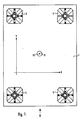
- Fig. 1 the work table 1 of a machine tool is shown schematically.
- Four supporting bodies 2, 3, 4 and 5 are arranged on the surface of the work table 1, each of which is provided with a plurality of centering pins.
- the detailed design of the support bodies 2-5 will be discussed in more detail below in connection with FIGS. 4 and 5. All four support bodies 2-5 are expediently of identical design.
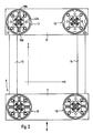
- a workpiece holder frame 6 is shown schematically in a view from below, i.e. with a view of the side facing the work table.
- the frame 6 is provided with a group of centering openings in the area of its four corners; their detailed training is also discussed in detail below.
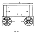
- FIG. 3 schematically shows a similar workpiece holding frame 7 as in FIG. 2, in a corresponding view, but which is only provided with two groups of centering openings.
- the frame 7 can be used on the same work table 1; then only two supporting bodies, for example the two supporting bodies 4 and 5, are used.
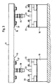
- the cross member 8 of the frame 7 rests on a support element 9 of the work table, which is expediently equipped with a compressed air outlet openings 10 in order to remove any dirt between the cross member 8 and the surface when the frame 7 is placed on it to blow away the support element 9.
- the workpiece holder frame 6 consists of two cross bars 11 and 12, which are connected to one another by means of two longitudinal bars 13 and 14. On the two longitudinal spars 13 and 14 receiving members for the workpieces to be machined can be attached (not shown); their training need not be discussed in the context of this description.
- the two cross bars 11 and 12 are each provided with two centering members 15 and 16 or 17 and 18, the structure of which is described in more detail below.
- the frame 7 according to FIG. 2a has the same cross member 11 with the two centering members 15 and 16, two shorter longitudinal members 13a and 14a and the cross member 8 already mentioned, which has no centering members.
- the frame 7 according to FIG. 2a is suitable for smaller workpieces or a small number of small workpieces; consequently, attachment at two locations is sufficient and the cross bar 8 can only rest loosely on the support element 9.
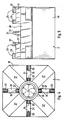
- a support body 2 is shown in a view from above, while in Fig. 5 the same support body can be seen in a side view.
- the support body 2 has a cylindrical lower part 19 and an essentially square upper part 20, the four corners of which are chamfered.
- Four projecting strips 21 are formed on the surface of the upper part 20 and run along the two center lines of the square.
- the actual centering pins are in turn molded onto the surface of the strips 21.
- the strips 21 carry four inner centering pins 22 and four outer centering pins 23.
- the centers of the four inner, somewhat narrower centering pins 22 lie on a circle of smaller diameter, and the centers of the four outer, somewhat wider centering pins 23 lie on a larger circle Diameter.
- the centering pins 22 and 23 are generally wedge-shaped and the arrangement is such that the free wedge edges 24 of opposite centering pins each lie on a line, the two imaginary lines intersecting at right angles.
- a ball chuck 25 with spring-loaded, pneumatically actuated clamping balls 26 is provided, which is used to receive a draw bolt.
- Such ball chucks are known per se and need not be discussed here.
- the centering pin 23 formed on the bar 21 has side surfaces that are inclined symmetrically to one another: an area 29 with a parallel side area adjacent to the bar 21 is adjoined by an area 29 with a weaker inclination, which merges into a head region 28 with a greater inclination.
- the centering pins 23 cooperate with centering slots. The more inclined head region 28 serves to facilitate the insertion of the centering pins into the slots, while the less inclined regions 29 perform the actual centering function.
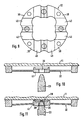
- FIGS. 6, 7 and 9 show a top view, a partial section along the line VII-VII in FIG. 6 and a view of the centering plate 32 from the side facing the cross member 11.
- a circular, projecting edge 31 is attached for each centering member 15 and 16, which serves as a system for a (not shown) dirt and moisture protection hood.
- a generally circular centering plate 32 which has a central opening 33, is fastened within the edge 31 of the centering member 15.
- a draw pin receptacle 34 penetrates the opening 33 and is e.g. fixed by means of screws 35 on the cross member 11.
- the receptacle 34 carries a vertically protruding draw bolt 36, which is designed such that it fits into the ball chuck 25 of the support body 2-5.
- the centering plate 32 is fastened to the cross bar with four screws 37; the screws 37 also serve as spacer bolts and rest with their surface on the surface-ground surface areas 27 of the support bodies 2-5 when the workpiece holder frame 6 is fastened on the work table 1. You thus determine the position of the frame 6 and thus the workpiece attached to it in the Z direction. At the points 38 where the centering plate 32 is screwed to the cross member 11, this is somewhat thicker, as can be clearly seen in FIG. 7.
- the thickened areas 38 of the centering plate 32 are in the case of the centering member 15 connected to each other by means of thin webs 40. All webs 40 have a thickened, central section 41, which is provided with a centering slot 39. The thickness of the central section 41 is slightly less than the thickness of the thickened areas 38, so that the central sections 41 do not rest on the surface of the cross member 11; this can be clearly seen in FIG. 7. Two opposite centering slots 39 lie on a straight line; these two straight lines intersect at right angles. The centering slots 39 extend over the entire width of the webs 40, and the depth of the centering slots 39 is approximately 50-70% of the thickness of the central sections 41.
- the central sections 41 are each with a blind bore 42 from the underside of the centering plate 32 provided, the position of which corresponds to the position of the outer centering pin 23 of the support body 2-5 in the example and whose diameter is somewhat larger than the largest dimension of the centering pin 23, seen in a section parallel to the surface of the upper part 20.
- the width of the centering slots 39 corresponds approximately to the width of the centering pins 23, measured in the middle of the region 29 which is less inclined.
- the central sections 41 with the centering slots 39 are elastically flexible in the axial direction, but absolutely rigid in the circumferential direction, ie within the plane of the centering plate 32.
- the height of the centering pin 23 is included Dimensioned such that they displace the central sections 41 against the cross bar 11 by a small amount when engaging in the centering slots 39. This shift is so small that the stability in the circumferential direction is not impaired.
- the centering element 16 is constructed in principle exactly the same, with the following differences:
- the centering element 17 (FIG. 2) is identical to the centering element 16, and therefore also has only two centering slots 39a.
- the centering plate 32 of the centering member 17 is installed rotated by 90 ° with respect to that of the centering member 16, so that the centering slots 39a of the centering member 17 in Longitudinal extension of the longitudinal spar 13 run.
- centering plate 32 of the centering member 18 has no centering slots at all, but only four through bores 42b corresponding to the position of the centering pins 23. Otherwise, the structure is the same as that of the remaining centering members.
- the X / Y reference position is defined by the intersection of the two straight lines through the opposite centering pins 23 of the supporting body 5, on which the centering member 15 is placed.
- the angular position of the centering member 15 is also theoretical and thus the frame 6 determined, however, due to the comparatively large dimensions of the latter with insufficient accuracy; due to the elasticity of the frame material, the position of the corner of the frame 6 diagonally opposite the centering element 15 could vary impermissibly. Therefore, the interaction of the two centering pins 23 of the support body 4 lying in the X direction with the two centering slots 39a of the centering member 16 additionally determines the Y position of the centering member 16.
- the remaining two centering pins 23 of the support body 4 have no function, since they dip into the through bores 42a of the centering plate 32 of the centering member 16.
- the interaction of the two centering pins 23 of the support body 3 lying in the Y direction with the two centering slots 39b of the centering member 17 additionally defines the X position of the centering member 17.
- the remaining two centering pins 23 of the support body 3 have no function since they dip into the through bores 42a of the centering plate 32 of the centering member 17.
- the centering pins 23 of the support body 2 have no effect at all, since they are all immersed in the through bores 42b of the centering member 18.
- the X / Y reference is formed by the one of the two claimed support body, namely by the one that receives the centering member 15, and the angular position is determined around the Z axis, while the other support body is on the the centering member 16 rests, additionally defines the X or Y position, depending on the orientation of the frame 7. This is sufficient in practice due to the comparatively smaller dimensions of the frame 7.
- all support bodies 2-5 are identical, although only one of the support bodies four centering pins come into operation.
- the X / Y position of the Z axis is determined only by the interaction of a single supporting body (eg 5 in FIG. 1) with the centering element 15 set.
- the position of the centering element 16 (FIG. 2), for example, which comes to rest on the supporting body 4, can vary in the X direction, since the centering slots 39a are long enough and the blind holes 42 are large enough to accommodate deviations.
- the centering members of the frame shown, for example are designed for relatively high loads and maximum rigidity. With smaller loads and smaller dimensions of the workpiece holder, simpler centering elements can be used, which can also have smaller dimensions.
- a simple spring steel washer can be used, which is provided with four cross-shaped, rectangular openings in which the inner centering pins 22 of the support bodies 2-5 engage.
- the same support body 2-5 can be used with both types of centering.
- the device according to the invention offers extraordinary Flexibility in the design of the workpiece holder a very high precision in terms of position accuracy. It is simple and inexpensive to manufacture, insensitive to dirt, since the system of the centering pin and centering slot is self-cleaning, and is not sensitive to wear. If the centering pins and / or the centering slots wear out somewhat after long use, only the centering plate 32 with its central section 41 is deformed somewhat less in the axial direction, but this has no influence on the positional accuracy.
Landscapes
- Engineering & Computer Science (AREA)
- Mechanical Engineering (AREA)
- Jigs For Machine Tools (AREA)
- Electrical Discharge Machining, Electrochemical Machining, And Combined Machining (AREA)
- Ladders (AREA)
- Forklifts And Lifting Vehicles (AREA)
- Constituent Portions Of Griding Lathes, Driving, Sensing And Control (AREA)
- Grinding Of Cylindrical And Plane Surfaces (AREA)
- Automobile Manufacture Line, Endless Track Vehicle, Trailer (AREA)
- Machine Tool Units (AREA)
Applications Claiming Priority (3)
| Application Number | Priority Date | Filing Date | Title |
|---|---|---|---|
| DE3919077 | 1989-06-10 | ||
| DE3919077A DE3919077C1 (fr) | 1989-06-10 | 1989-06-10 | |
| SG6694A SG6694G (en) | 1989-06-10 | 1994-01-17 | Device for induced clamping of a workpiece on a processing table |
Publications (4)
| Publication Number | Publication Date |
|---|---|
| EP0403428A2 true EP0403428A2 (fr) | 1990-12-19 |
| EP0403428A3 EP0403428A3 (fr) | 1991-05-08 |
| EP0403428B1 EP0403428B1 (fr) | 1993-10-20 |
| EP0403428B2 EP0403428B2 (fr) | 2001-01-31 |
Family
ID=25881834
Family Applications (1)
| Application Number | Title | Priority Date | Filing Date |
|---|---|---|---|
| EP90810402A Expired - Lifetime EP0403428B2 (fr) | 1989-06-10 | 1990-06-01 | Dispositif pour l'abloquage indixé d'une pièce sur une table d'usinage |
Country Status (14)
| Country | Link |
|---|---|
| US (1) | US5065991A (fr) |
| EP (1) | EP0403428B2 (fr) |
| JP (1) | JPH0755425B2 (fr) |
| KR (1) | KR0133516B1 (fr) |
| CN (1) | CN1023087C (fr) |
| AT (1) | ATE96070T1 (fr) |
| AU (1) | AU628582B2 (fr) |
| CA (1) | CA2018696C (fr) |
| DE (2) | DE3919077C1 (fr) |
| DK (1) | DK0403428T4 (fr) |
| ES (1) | ES2046761T5 (fr) |
| FI (1) | FI93178C (fr) |
| HK (1) | HK4494A (fr) |
| SG (1) | SG6694G (fr) |
Cited By (7)
| Publication number | Priority date | Publication date | Assignee | Title |
|---|---|---|---|---|
| DE4314629A1 (de) * | 1993-05-04 | 1994-11-10 | Erowa Ag | Einrichtung zum positionsdefinierten Aufspannen eines Werkstücks am Arbeitsplatz einer Bearbeitungsmaschine |
| EP0614725A3 (fr) * | 1993-03-09 | 1995-01-25 | Erowa Ag | Dispositif pour l'abloquage indixé d'une pièce au poste de travail d'une machine d'usinage. |
| DE4326275A1 (de) * | 1993-08-05 | 1995-02-09 | Erowa Ag | Verfahren zum Positionieren eines Werkstückträgers in einer Bearbeitungsmaschine sowie zugehöriger Werkstückträger |
| DE19716797A1 (de) * | 1997-04-22 | 1998-11-05 | Emil Stark | Lagerichtige Ein-Nippel-Einspannung |
| DE102010005886A1 (de) * | 2010-01-27 | 2011-07-28 | Stark Spannsysteme Gmbh | Spannvorrichtung mit einem Höhenausgleich |
| EP3263274A1 (fr) | 2016-06-30 | 2018-01-03 | Erowa AG | Dispositif de serrage et système de serrage |
| EP4194141A1 (fr) | 2021-12-13 | 2023-06-14 | Erowa AG | Dispositif de serrage |
Families Citing this family (54)
| Publication number | Priority date | Publication date | Assignee | Title |
|---|---|---|---|---|
| US5246218A (en) * | 1992-09-25 | 1993-09-21 | Intel Corporation | Apparatus for securing an automatically loaded wafer cassette on a wafer processing equipment |
| US5369864A (en) * | 1993-05-27 | 1994-12-06 | Built For Speed, Inc. | Tool kit for roller skates |
| DE4428310A1 (de) * | 1994-08-10 | 1996-02-15 | Manfred Schanz | Befestigungsvorrichtung für ein Werkzeug oder Werkstück |
| JPH08118175A (ja) * | 1994-10-21 | 1996-05-14 | Imao Corp:Kk | 取付用ベース部材及びそのベース部材に取り付けられる取付具 |
| DE29516236U1 (de) * | 1995-10-13 | 1995-11-30 | Gärtner, Erwin, 91438 Bad Windsheim | Spannplatte für eine Aufspannvorrichtung |
| DE59705344D1 (de) * | 1996-06-17 | 2001-12-20 | Certa Ag Reinach | Aufspannvorrichtung sowie Einrichtung zum positionsdefinierten Aufspannen eines Werkzeugs oder Werkstücks |
| US5779203A (en) * | 1996-06-28 | 1998-07-14 | Edlinger; Erich | Adjustable wafer cassette stand |
| DE19636375A1 (de) * | 1996-09-09 | 1998-03-12 | Emil Stark | Schnellverschluß für eine Palette unter Späneflug |
| DE29702577U1 (de) * | 1997-02-14 | 1997-08-28 | Stark, Emil, Götzis | Schnellspannzylinder mit Flüssigkeitsablauf |
| DE19739460C1 (de) * | 1997-09-03 | 1999-02-11 | Hohenstein Vorrichtungsbau | Schnell-Paß-System für Bauteile von Werkzeugmaschinen |
| EP0922529B1 (fr) * | 1997-12-11 | 2002-11-06 | Parotec AG | Unité pour connecter temporairement des parties d'un dispositif de palletisation et un dispositif de palettisation |
| US6015961A (en) * | 1997-12-24 | 2000-01-18 | Precision Die & Machine Co. | EDM tool holder |
| US6186711B1 (en) | 1998-04-03 | 2001-02-13 | Axxess Technologies, Inc. | Engraving system |
| DE19858159C2 (de) * | 1998-12-16 | 2003-07-10 | System 3R Internat Ab Vaelling | Kupplungsvorrichtung |
| DE19917005C1 (de) * | 1999-04-15 | 2000-10-12 | Vischer & Bolli Ag Duebendorf | Spanneinrichtung |
| EP1068918B1 (fr) * | 1999-07-14 | 2004-10-20 | Erowa AG | Dispositif de serrage d'une pièce dans une position definie dans une zône de travail d' une machine d'usinage |
| DE29915750U1 (de) | 1999-09-09 | 2000-01-05 | Müller GmbH Formenbau, 35236 Breidenbach | Spanneinrichtung zum Befestigen von Erodierelektroden an den Halteelementen von Fräsmaschinen und Erodiermaschinen |
| DE19943605C2 (de) * | 1999-09-11 | 2002-06-20 | Hohenstein Vorrichtungsbau | Adaptive Werkstückspannvorrichtung |
| US6252192B1 (en) | 2000-01-18 | 2001-06-26 | Precision Die & Machine Company | EDM tool holder |
| DE10101179A1 (de) * | 2001-01-12 | 2002-07-18 | Audi Ag | Vorrichtung zur positionsdefinierten Aufnahme eines Werkstücks, insbesondere eines Karosserieteils |
| JP2002346872A (ja) * | 2001-05-18 | 2002-12-04 | Aska Trading Kk | L型パレットベースおよびその交換装置 |
| DE10155077B4 (de) * | 2001-11-09 | 2004-07-29 | Lang, Günter | Wiederholgenaue Spanneinrichtung |
| TW592882B (en) | 2001-12-19 | 2004-06-21 | Erowa Ag | Clamping apparatus with a clamping chuck and a work piece carrier releasable connectable thereto |
| EP1428611A1 (fr) * | 2002-12-13 | 2004-06-16 | Jürgen Mettchen | Dispositif de serrage pour serrer un boulon d'ancrage avec rainures |
| DE502005002952D1 (de) * | 2004-04-22 | 2008-04-10 | Erowa Ag | Spanneinrichtung mit einem Spannfutter und einer lösbar daran fixierbaren Palette |
| PL1666195T3 (pl) * | 2004-12-01 | 2007-10-31 | Erowa Ag | Urządzenie mocujące do rozłącznego ustalania palety, z elementem tłumiącym |
| EP1704957B1 (fr) * | 2005-03-24 | 2008-07-30 | System 3R International AB | Dispositif d'accouplement avec des parties élastiques pour une orientation en X et Y. |
| DE102005030820B3 (de) * | 2005-07-01 | 2006-08-17 | Ott-Jakob Gmbh & Co. Spanntechnik Kg | Spannvorrichtung |
| TW200732083A (en) * | 2006-01-30 | 2007-09-01 | Tool Internat Ag F | Clamping apparatus |
| US7766628B2 (en) * | 2006-04-13 | 2010-08-03 | Scroll Technologies | Sealed compressor with structure on lower housing shell to assist weld placement |
| US8307522B2 (en) * | 2006-09-04 | 2012-11-13 | Makino Milling Machine Co., Ltd. | Machine tool and pallet standby station |
| US7894935B1 (en) | 2007-05-03 | 2011-02-22 | Tagworks, LLC | Public use pet tag marking kiosk |
| US7853353B1 (en) | 2007-05-03 | 2010-12-14 | Tagworks, LLC | Public use pet tag marking kiosk |
| US8050796B1 (en) | 2007-05-03 | 2011-11-01 | Tagworks, LLC | Public use pet tag marking kiosk |
| US8403314B2 (en) * | 2007-09-07 | 2013-03-26 | Robert Bosch Gmbh | Dog hole layout for a workbench system |
| CH699231B1 (de) * | 2008-07-22 | 2012-03-30 | Erowa Ag | Spanneinrichtung. |
| CN102236033A (zh) * | 2010-04-30 | 2011-11-09 | 向熙科技股份有限公司 | 不需治具盘的自动定位设备及电性量测系统 |
| CN102355971B (zh) * | 2010-05-18 | 2013-10-23 | 苹果公司 | 用于制造设备的可拆卸固定装置 |
| CH703777A2 (de) * | 2010-09-14 | 2012-03-15 | Parotec Ag | Vorrichtung zur positionsdefinierten Aufspannung eines Gegenstandes. |
| DE102010037546A1 (de) * | 2010-09-15 | 2012-03-15 | Klaus Hofmann | Sicherungs-Spannvorrichtung |
| CN102059559B (zh) * | 2010-12-30 | 2013-04-24 | 晋江市威坦机械开发有限公司 | 一种数控机床立式回转工作台 |
| CN102501084A (zh) * | 2011-10-24 | 2012-06-20 | 格力电器(郑州)有限公司 | 旋转定位机构及具有该旋转定位机构的旋转工艺板装置 |
| CN102529278B (zh) * | 2012-01-11 | 2015-03-25 | 郑春晓 | 贴片机的十字校正机构 |
| KR20160063626A (ko) | 2014-11-27 | 2016-06-07 | 주식회사 경영하이텍 | 수평형 머시닝 센터의 공작물 고정장치 |
| TWI608895B (zh) * | 2015-11-09 | 2017-12-21 | Cherng Jin Technology Co Ltd | Fixture mold base |
| CN105500089B (zh) * | 2015-12-28 | 2017-07-04 | 广船国际有限公司 | 轴孔中心定位器 |
| DE102016210508A1 (de) * | 2016-06-14 | 2017-12-14 | Gildemeister Drehmaschinen Gmbh | Handhabungsvorrichtung zum Einsatz an einer Werkzeugmaschine |
| JP6434463B2 (ja) * | 2016-08-30 | 2018-12-05 | ファナック株式会社 | ワークをクランプするパレット装置、工作機械、および加工システム |
| CN107755601A (zh) * | 2017-12-01 | 2018-03-06 | 陈飞华 | 一种建筑用钢筋切割机 |
| CN109396916A (zh) * | 2018-09-19 | 2019-03-01 | 广州市昊志机电股份有限公司 | 一种零点定位装置以及一种机床 |
| EP3628440B1 (fr) | 2018-09-27 | 2022-03-16 | MAGNA STEYR Fahrzeugtechnik AG & Co KG | Dispositif de positionnement |
| CN111673511B (zh) * | 2020-06-18 | 2022-02-08 | 潍坊工程职业学院 | 一种高速离心式部件夹持器 |
| SE544647C2 (en) * | 2020-10-21 | 2022-10-04 | Zerofix Tooling Ab | Positioning device for a positioning system |
| DE102021134477B4 (de) | 2021-12-23 | 2023-11-16 | Gebr. Heller Maschinenfabrik Gmbh | Werkzeugmaschine und Verfahren zur Bestückung und/oder Entstückung der Werkzeugmaschine mit einer Werkstückpalette |
Family Cites Families (12)
| Publication number | Priority date | Publication date | Assignee | Title |
|---|---|---|---|---|
| US4148400A (en) * | 1977-03-07 | 1979-04-10 | The Cross Company | Pallet locator and clamping assembly |
| JPS5741150A (en) * | 1980-08-18 | 1982-03-08 | Cincinnati Milacron Chem | Arranging device for pallet |
| US4735671A (en) * | 1983-01-31 | 1988-04-05 | Xerox Corporation | Method for fabricating full width scanning arrays |
| US4610020A (en) * | 1984-01-06 | 1986-09-02 | The Perkin-Elmer Corporation | X-ray mask ring and apparatus for making same |
| ES8703099A1 (es) * | 1984-11-01 | 1987-02-16 | Buechler B Set Ag | Instalacion para el soporte de un objeto |
| US4586702A (en) * | 1985-08-05 | 1986-05-06 | Rca Corporation | System for orienting one body relative to a second body in three orthogonal directions |
| JPS6257838A (ja) * | 1985-09-05 | 1987-03-13 | Honda Motor Co Ltd | 治具装置用位置決め機構 |
| JPH031123Y2 (fr) * | 1985-09-10 | 1991-01-16 | ||
| DE3729601C1 (de) * | 1987-09-04 | 1988-10-27 | Erowa Ag | Vorrichtung zum Aufspannen eines Werkstueckes oder Werkzeuges |
| WO1989003276A1 (fr) * | 1987-10-13 | 1989-04-20 | Extrude Hone Corp | Procede et appareil d'alignement de deux composants |
| US4932642A (en) * | 1988-04-12 | 1990-06-12 | Hines Industries, Inc. | Workpiece support tooling |
| US4928939A (en) * | 1989-08-03 | 1990-05-29 | Bell Michael G | Locator and clamping means for a jig fixture |
-
1989
- 1989-06-10 DE DE3919077A patent/DE3919077C1/de not_active Expired - Lifetime
-
1990
- 1990-06-01 AT AT90810402T patent/ATE96070T1/de not_active IP Right Cessation
- 1990-06-01 DE DE90810402T patent/DE59003117D1/de not_active Expired - Fee Related
- 1990-06-01 DK DK90810402T patent/DK0403428T4/da active
- 1990-06-01 ES ES90810402T patent/ES2046761T5/es not_active Expired - Lifetime
- 1990-06-01 EP EP90810402A patent/EP0403428B2/fr not_active Expired - Lifetime
- 1990-06-06 AU AU56879/90A patent/AU628582B2/en not_active Ceased
- 1990-06-06 US US07/533,876 patent/US5065991A/en not_active Expired - Lifetime
- 1990-06-08 JP JP2151430A patent/JPH0755425B2/ja not_active Expired - Fee Related
- 1990-06-09 KR KR1019900008463A patent/KR0133516B1/ko not_active Expired - Fee Related
- 1990-06-09 CN CN90104909A patent/CN1023087C/zh not_active Expired - Fee Related
- 1990-06-11 CA CA002018696A patent/CA2018696C/fr not_active Expired - Fee Related
- 1990-06-11 FI FI902912A patent/FI93178C/fi not_active IP Right Cessation
-
1994
- 1994-01-13 HK HK44/94A patent/HK4494A/xx not_active IP Right Cessation
- 1994-01-17 SG SG6694A patent/SG6694G/en unknown
Cited By (12)
| Publication number | Priority date | Publication date | Assignee | Title |
|---|---|---|---|---|
| EP0614725A3 (fr) * | 1993-03-09 | 1995-01-25 | Erowa Ag | Dispositif pour l'abloquage indixé d'une pièce au poste de travail d'une machine d'usinage. |
| AU669044B2 (en) * | 1993-03-09 | 1996-05-23 | Erowa Ag | An apparatus for clamping a work piece at a work station of a machining apparatus in a well defined position |
| DE4314629A1 (de) * | 1993-05-04 | 1994-11-10 | Erowa Ag | Einrichtung zum positionsdefinierten Aufspannen eines Werkstücks am Arbeitsplatz einer Bearbeitungsmaschine |
| EP0624428A2 (fr) | 1993-05-04 | 1994-11-17 | Erowa AG | Dispositif pour le blocage indexé d'une pièce à un poste de travail d'une machine d'usinage |
| EP0624428A3 (fr) * | 1993-05-04 | 1995-01-25 | Erowa Ag | Dispositif pour le blocage indexé d'une pièce à un poste de travail d'une machine d'usinage. |
| DE4326275A1 (de) * | 1993-08-05 | 1995-02-09 | Erowa Ag | Verfahren zum Positionieren eines Werkstückträgers in einer Bearbeitungsmaschine sowie zugehöriger Werkstückträger |
| DE19716797A1 (de) * | 1997-04-22 | 1998-11-05 | Emil Stark | Lagerichtige Ein-Nippel-Einspannung |
| DE102010005886A1 (de) * | 2010-01-27 | 2011-07-28 | Stark Spannsysteme Gmbh | Spannvorrichtung mit einem Höhenausgleich |
| EP2353774A1 (fr) | 2010-01-27 | 2011-08-10 | Stark Spannsysteme GmbH | Dispositif de serrage doté d'un sytème de compensation en hauteur |
| DE102010005886B4 (de) * | 2010-01-27 | 2012-01-19 | Stark Spannsysteme Gmbh | Spannvorrichtung mit einem Höhenausgleich |
| EP3263274A1 (fr) | 2016-06-30 | 2018-01-03 | Erowa AG | Dispositif de serrage et système de serrage |
| EP4194141A1 (fr) | 2021-12-13 | 2023-06-14 | Erowa AG | Dispositif de serrage |
Also Published As
| Publication number | Publication date |
|---|---|
| JPH0755425B2 (ja) | 1995-06-14 |
| DK0403428T3 (da) | 1994-01-17 |
| CN1023087C (zh) | 1993-12-15 |
| FI902912A0 (fi) | 1990-06-11 |
| CA2018696A1 (fr) | 1990-12-10 |
| ES2046761T5 (es) | 2001-04-01 |
| DE3919077C1 (fr) | 1990-07-26 |
| EP0403428B1 (fr) | 1993-10-20 |
| AU628582B2 (en) | 1992-09-17 |
| FI93178B (fi) | 1994-11-30 |
| HK4494A (en) | 1994-01-21 |
| CA2018696C (fr) | 1994-05-03 |
| FI93178C (fi) | 1995-03-10 |
| ATE96070T1 (de) | 1993-11-15 |
| CN1048345A (zh) | 1991-01-09 |
| KR910000296A (ko) | 1991-01-29 |
| US5065991A (en) | 1991-11-19 |
| DE59003117D1 (de) | 1993-11-25 |
| EP0403428A3 (fr) | 1991-05-08 |
| SG6694G (en) | 1994-04-15 |
| KR0133516B1 (ko) | 1999-05-01 |
| EP0403428B2 (fr) | 2001-01-31 |
| DK0403428T4 (da) | 2001-03-19 |
| AU5687990A (en) | 1990-12-13 |
| JPH0332541A (ja) | 1991-02-13 |
| ES2046761T3 (es) | 1994-02-01 |
Similar Documents
| Publication | Publication Date | Title |
|---|---|---|
| EP0403428B1 (fr) | Dispositif pour l'abloquage indixé d'une pièce sur une table d'usinage | |
| EP0818270B1 (fr) | Dispositif de serrage et dispositif pour le blocage indexé d'une pièce de travail ou d'un outil | |
| EP0697267B1 (fr) | Dispositif de fixation pour un outil ou une pièce | |
| DE69622376T2 (de) | Spannsystem fur schneideinsatze und dazugehorende schneideinsatz | |
| EP0308370B1 (fr) | Dispositif pour fixer une pièce ou un outil | |
| EP0267352B1 (fr) | Dispositif pour fixer d'une manière réitérable et très précise la position dans l'espace d'un premier objet par rapport à d'autres objets | |
| EP0900618A1 (fr) | Plaque de montage pour une pièce à usiner | |
| DE1901139A1 (de) | Vorrichtung zum Halten von Werkstuecken zwecks maschineller Bearbeitung | |
| EP0074565A2 (fr) | Palette pour le positionnement et le serrage de pièces à usiner | |
| EP0248116A2 (fr) | Dispositif pour serrer des pièces à travailler non tournantes | |
| EP1033210B1 (fr) | Plaquette de coupe, en particulier pour un outil de fraisage | |
| DE69117544T2 (de) | Gewindeschneideinsatz | |
| DE3437260A1 (de) | Werkstueck-positioniervorrichtung | |
| DE3441968A1 (de) | Gegenstandsfeststeller, -aufspannvorrichtung und bearbeitungsverfahren | |
| DE9203992U1 (de) | Vorrichtung zum Ankuppeln eines Werkstückes oder eines Werkzeuges an eine Werkzeugmaschine, insbesondere einer Elektrode an eine Funkenerosionsmaschine | |
| EP0617651B1 (fr) | Dispositif d'usinage ou d'inspection, notamment machine-outil, a table de serrage pour objets a serrer | |
| DE3618521C1 (en) | Device for clamping in position non-rotating workpieces | |
| DE3739996C2 (de) | Fräswerkzeug mit Wendekantenbrecher | |
| DE4337861A1 (de) | Modulare keilförmige Halteelemente | |
| CH688031A5 (de) | Vorrichtung zum positionsdefinierten Aufspannen eines Werkstuecks auf einem Bearbeitungstisch. | |
| CH688508A5 (de) | Werkstueckpalette. | |
| CH673245A5 (fr) | ||
| DE29802835U1 (de) | Kupplung mit zwei Kupplungsorganen und einer Spannvorrichtung | |
| DE3415189C2 (fr) | ||
| DE10317349B4 (de) | Kombination aus einemSchnellspannzylinder und einer lagerichtig auf dem selben aufliegenden Werkstückpalette |
Legal Events
| Date | Code | Title | Description |
|---|---|---|---|
| PUAI | Public reference made under article 153(3) epc to a published international application that has entered the european phase |
Free format text: ORIGINAL CODE: 0009012 |
|
| AK | Designated contracting states |
Kind code of ref document: A2 Designated state(s): AT BE CH DE DK ES FR GB GR IT LI LU NL SE |
|
| PUAL | Search report despatched |
Free format text: ORIGINAL CODE: 0009013 |
|
| AK | Designated contracting states |
Kind code of ref document: A3 Designated state(s): AT BE CH DE DK ES FR GB GR IT LI LU NL SE |
|
| 17P | Request for examination filed |
Effective date: 19910524 |
|
| 17Q | First examination report despatched |
Effective date: 19920911 |
|
| GRAA | (expected) grant |
Free format text: ORIGINAL CODE: 0009210 |
|
| AK | Designated contracting states |
Kind code of ref document: B1 Designated state(s): AT BE CH DE DK ES FR GB GR IT LI LU NL SE |
|
| REF | Corresponds to: |
Ref document number: 96070 Country of ref document: AT Date of ref document: 19931115 Kind code of ref document: T |
|
| REF | Corresponds to: |
Ref document number: 59003117 Country of ref document: DE Date of ref document: 19931125 |
|
| GBT | Gb: translation of ep patent filed (gb section 77(6)(a)/1977) |
Effective date: 19931103 |
|
| ITF | It: translation for a ep patent filed | ||
| REG | Reference to a national code |
Ref country code: DK Ref legal event code: T3 |
|
| REG | Reference to a national code |
Ref country code: ES Ref legal event code: FG2A Ref document number: 2046761 Country of ref document: ES Kind code of ref document: T3 |
|
| ET | Fr: translation filed | ||
| REG | Reference to a national code |
Ref country code: GR Ref legal event code: FG4A Free format text: 3010265 |
|
| PLBI | Opposition filed |
Free format text: ORIGINAL CODE: 0009260 |
|
| EPTA | Lu: last paid annual fee | ||
| 26 | Opposition filed |
Opponent name: SYSTEM 3R INTERNATIONAL AB Effective date: 19940719 |
|
| NLR1 | Nl: opposition has been filed with the epo |
Opponent name: SYSTEM 3R INTERNATIONAL AB. |
|
| EAL | Se: european patent in force in sweden |
Ref document number: 90810402.9 |
|
| PLAW | Interlocutory decision in opposition |
Free format text: ORIGINAL CODE: EPIDOS IDOP |
|
| APAC | Appeal dossier modified |
Free format text: ORIGINAL CODE: EPIDOS NOAPO |
|
| APAE | Appeal reference modified |
Free format text: ORIGINAL CODE: EPIDOS REFNO |
|
| PGFP | Annual fee paid to national office [announced via postgrant information from national office to epo] |
Ref country code: GR Payment date: 19970530 Year of fee payment: 8 |
|
| APAC | Appeal dossier modified |
Free format text: ORIGINAL CODE: EPIDOS NOAPO |
|
| PGFP | Annual fee paid to national office [announced via postgrant information from national office to epo] |
Ref country code: LU Payment date: 19971001 Year of fee payment: 8 |
|
| PG25 | Lapsed in a contracting state [announced via postgrant information from national office to epo] |
Ref country code: LU Free format text: LAPSE BECAUSE OF NON-PAYMENT OF DUE FEES Effective date: 19980601 |
|
| PG25 | Lapsed in a contracting state [announced via postgrant information from national office to epo] |
Ref country code: GR Free format text: LAPSE BECAUSE OF NON-PAYMENT OF DUE FEES Effective date: 19980630 |
|
| APAE | Appeal reference modified |
Free format text: ORIGINAL CODE: EPIDOS REFNO |
|
| APAC | Appeal dossier modified |
Free format text: ORIGINAL CODE: EPIDOS NOAPO |
|
| PLAW | Interlocutory decision in opposition |
Free format text: ORIGINAL CODE: EPIDOS IDOP |
|
| PUAH | Patent maintained in amended form |
Free format text: ORIGINAL CODE: 0009272 |
|
| STAA | Information on the status of an ep patent application or granted ep patent |
Free format text: STATUS: PATENT MAINTAINED AS AMENDED |
|
| 27A | Patent maintained in amended form |
Effective date: 20010131 |
|
| AK | Designated contracting states |
Kind code of ref document: B2 Designated state(s): AT BE CH DE DK ES FR GB GR IT LI LU NL SE |
|
| REG | Reference to a national code |
Ref country code: CH Ref legal event code: AEN Free format text: AUFRECHTERHALTUNG DES PATENTES IN GEAENDERTER FORM |
|
| REG | Reference to a national code |
Ref country code: DK Ref legal event code: T4 |
|
| ET3 | Fr: translation filed ** decision concerning opposition | ||
| REG | Reference to a national code |
Ref country code: ES Ref legal event code: DC2A Kind code of ref document: T5 Effective date: 20010226 |
|
| NLR2 | Nl: decision of opposition | ||
| NLR3 | Nl: receipt of modified translations in the netherlands language after an opposition procedure | ||
| ITF | It: translation for a ep patent filed | ||
| GBTA | Gb: translation of amended ep patent filed (gb section 77(6)(b)/1977) | ||
| REG | Reference to a national code |
Ref country code: GB Ref legal event code: IF02 |
|
| PGFP | Annual fee paid to national office [announced via postgrant information from national office to epo] |
Ref country code: AT Payment date: 20050510 Year of fee payment: 16 |
|
| PGFP | Annual fee paid to national office [announced via postgrant information from national office to epo] |
Ref country code: FR Payment date: 20050512 Year of fee payment: 16 |
|
| PGFP | Annual fee paid to national office [announced via postgrant information from national office to epo] |
Ref country code: GB Payment date: 20050516 Year of fee payment: 16 |
|
| PGFP | Annual fee paid to national office [announced via postgrant information from national office to epo] |
Ref country code: NL Payment date: 20050517 Year of fee payment: 16 |
|
| PGFP | Annual fee paid to national office [announced via postgrant information from national office to epo] |
Ref country code: DK Payment date: 20050518 Year of fee payment: 16 |
|
| PGFP | Annual fee paid to national office [announced via postgrant information from national office to epo] |
Ref country code: SE Payment date: 20050519 Year of fee payment: 16 Ref country code: CH Payment date: 20050519 Year of fee payment: 16 |
|
| PGFP | Annual fee paid to national office [announced via postgrant information from national office to epo] |
Ref country code: DE Payment date: 20050520 Year of fee payment: 16 |
|
| PGFP | Annual fee paid to national office [announced via postgrant information from national office to epo] |
Ref country code: BE Payment date: 20050606 Year of fee payment: 16 |
|
| PGFP | Annual fee paid to national office [announced via postgrant information from national office to epo] |
Ref country code: ES Payment date: 20050607 Year of fee payment: 16 |
|
| APAH | Appeal reference modified |
Free format text: ORIGINAL CODE: EPIDOSCREFNO |
|
| PG25 | Lapsed in a contracting state [announced via postgrant information from national office to epo] |
Ref country code: GB Free format text: LAPSE BECAUSE OF NON-PAYMENT OF DUE FEES Effective date: 20060601 Ref country code: AT Free format text: LAPSE BECAUSE OF NON-PAYMENT OF DUE FEES Effective date: 20060601 |
|
| PG25 | Lapsed in a contracting state [announced via postgrant information from national office to epo] |
Ref country code: SE Free format text: LAPSE BECAUSE OF NON-PAYMENT OF DUE FEES Effective date: 20060602 Ref country code: ES Free format text: LAPSE BECAUSE OF NON-PAYMENT OF DUE FEES Effective date: 20060602 |
|
| PG25 | Lapsed in a contracting state [announced via postgrant information from national office to epo] |
Ref country code: LI Free format text: LAPSE BECAUSE OF NON-PAYMENT OF DUE FEES Effective date: 20060630 Ref country code: DK Free format text: LAPSE BECAUSE OF NON-PAYMENT OF DUE FEES Effective date: 20060630 Ref country code: CH Free format text: LAPSE BECAUSE OF NON-PAYMENT OF DUE FEES Effective date: 20060630 Ref country code: BE Free format text: LAPSE BECAUSE OF NON-PAYMENT OF DUE FEES Effective date: 20060630 |
|
| PGFP | Annual fee paid to national office [announced via postgrant information from national office to epo] |
Ref country code: IT Payment date: 20060630 Year of fee payment: 17 |
|
| PG25 | Lapsed in a contracting state [announced via postgrant information from national office to epo] |
Ref country code: NL Free format text: LAPSE BECAUSE OF NON-PAYMENT OF DUE FEES Effective date: 20070101 |
|
| PG25 | Lapsed in a contracting state [announced via postgrant information from national office to epo] |
Ref country code: DE Free format text: LAPSE BECAUSE OF NON-PAYMENT OF DUE FEES Effective date: 20070103 |
|
| REG | Reference to a national code |
Ref country code: DK Ref legal event code: EBP |
|
| REG | Reference to a national code |
Ref country code: CH Ref legal event code: PL |
|
| EUG | Se: european patent has lapsed | ||
| GBPC | Gb: european patent ceased through non-payment of renewal fee |
Effective date: 20060601 |
|
| NLV4 | Nl: lapsed or anulled due to non-payment of the annual fee |
Effective date: 20070101 |
|
| REG | Reference to a national code |
Ref country code: FR Ref legal event code: ST Effective date: 20070228 |
|
| REG | Reference to a national code |
Ref country code: ES Ref legal event code: FD2A Effective date: 20060602 |
|
| BERE | Be: lapsed |
Owner name: *EROWA A.G. Effective date: 20060630 |
|
| PG25 | Lapsed in a contracting state [announced via postgrant information from national office to epo] |
Ref country code: FR Free format text: LAPSE BECAUSE OF NON-PAYMENT OF DUE FEES Effective date: 20060630 |
|
| PG25 | Lapsed in a contracting state [announced via postgrant information from national office to epo] |
Ref country code: IT Free format text: LAPSE BECAUSE OF NON-PAYMENT OF DUE FEES Effective date: 20070601 |