EP3263274A1 - Dispositif de serrage et système de serrage - Google Patents
Dispositif de serrage et système de serrage Download PDFInfo
- Publication number
- EP3263274A1 EP3263274A1 EP17000673.8A EP17000673A EP3263274A1 EP 3263274 A1 EP3263274 A1 EP 3263274A1 EP 17000673 A EP17000673 A EP 17000673A EP 3263274 A1 EP3263274 A1 EP 3263274A1
- Authority
- EP
- European Patent Office
- Prior art keywords
- clamping
- chuck
- centering
- receiving opening
- chucks
- Prior art date
- Legal status (The legal status is an assumption and is not a legal conclusion. Google has not performed a legal analysis and makes no representation as to the accuracy of the status listed.)
- Granted
Links
Images


Classifications
-
- B—PERFORMING OPERATIONS; TRANSPORTING
- B23—MACHINE TOOLS; METAL-WORKING NOT OTHERWISE PROVIDED FOR
- B23Q—DETAILS, COMPONENTS, OR ACCESSORIES FOR MACHINE TOOLS, e.g. ARRANGEMENTS FOR COPYING OR CONTROLLING; MACHINE TOOLS IN GENERAL CHARACTERISED BY THE CONSTRUCTION OF PARTICULAR DETAILS OR COMPONENTS; COMBINATIONS OR ASSOCIATIONS OF METAL-WORKING MACHINES, NOT DIRECTED TO A PARTICULAR RESULT
- B23Q1/00—Members which are comprised in the general build-up of a form of machine, particularly relatively large fixed members
- B23Q1/0063—Connecting non-slidable parts of machine tools to each other
- B23Q1/0072—Connecting non-slidable parts of machine tools to each other using a clamping opening for receiving an insertion bolt or nipple
-
- B—PERFORMING OPERATIONS; TRANSPORTING
- B23—MACHINE TOOLS; METAL-WORKING NOT OTHERWISE PROVIDED FOR
- B23Q—DETAILS, COMPONENTS, OR ACCESSORIES FOR MACHINE TOOLS, e.g. ARRANGEMENTS FOR COPYING OR CONTROLLING; MACHINE TOOLS IN GENERAL CHARACTERISED BY THE CONSTRUCTION OF PARTICULAR DETAILS OR COMPONENTS; COMBINATIONS OR ASSOCIATIONS OF METAL-WORKING MACHINES, NOT DIRECTED TO A PARTICULAR RESULT
- B23Q3/00—Devices holding, supporting, or positioning work or tools, of a kind normally removable from the machine
- B23Q3/02—Devices holding, supporting, or positioning work or tools, of a kind normally removable from the machine for mounting on a work-table, tool-slide, or analogous part
-
- B—PERFORMING OPERATIONS; TRANSPORTING
- B23—MACHINE TOOLS; METAL-WORKING NOT OTHERWISE PROVIDED FOR
- B23Q—DETAILS, COMPONENTS, OR ACCESSORIES FOR MACHINE TOOLS, e.g. ARRANGEMENTS FOR COPYING OR CONTROLLING; MACHINE TOOLS IN GENERAL CHARACTERISED BY THE CONSTRUCTION OF PARTICULAR DETAILS OR COMPONENTS; COMBINATIONS OR ASSOCIATIONS OF METAL-WORKING MACHINES, NOT DIRECTED TO A PARTICULAR RESULT
- B23Q3/00—Devices holding, supporting, or positioning work or tools, of a kind normally removable from the machine
- B23Q3/02—Devices holding, supporting, or positioning work or tools, of a kind normally removable from the machine for mounting on a work-table, tool-slide, or analogous part
- B23Q3/06—Work-clamping means
-
- B—PERFORMING OPERATIONS; TRANSPORTING
- B23—MACHINE TOOLS; METAL-WORKING NOT OTHERWISE PROVIDED FOR
- B23Q—DETAILS, COMPONENTS, OR ACCESSORIES FOR MACHINE TOOLS, e.g. ARRANGEMENTS FOR COPYING OR CONTROLLING; MACHINE TOOLS IN GENERAL CHARACTERISED BY THE CONSTRUCTION OF PARTICULAR DETAILS OR COMPONENTS; COMBINATIONS OR ASSOCIATIONS OF METAL-WORKING MACHINES, NOT DIRECTED TO A PARTICULAR RESULT
- B23Q3/00—Devices holding, supporting, or positioning work or tools, of a kind normally removable from the machine
- B23Q3/02—Devices holding, supporting, or positioning work or tools, of a kind normally removable from the machine for mounting on a work-table, tool-slide, or analogous part
- B23Q3/10—Auxiliary devices, e.g. bolsters, extension members
- B23Q3/102—Auxiliary devices, e.g. bolsters, extension members for fixing elements in slots
-
- B—PERFORMING OPERATIONS; TRANSPORTING
- B23—MACHINE TOOLS; METAL-WORKING NOT OTHERWISE PROVIDED FOR
- B23Q—DETAILS, COMPONENTS, OR ACCESSORIES FOR MACHINE TOOLS, e.g. ARRANGEMENTS FOR COPYING OR CONTROLLING; MACHINE TOOLS IN GENERAL CHARACTERISED BY THE CONSTRUCTION OF PARTICULAR DETAILS OR COMPONENTS; COMBINATIONS OR ASSOCIATIONS OF METAL-WORKING MACHINES, NOT DIRECTED TO A PARTICULAR RESULT
- B23Q3/00—Devices holding, supporting, or positioning work or tools, of a kind normally removable from the machine
- B23Q3/02—Devices holding, supporting, or positioning work or tools, of a kind normally removable from the machine for mounting on a work-table, tool-slide, or analogous part
- B23Q3/10—Auxiliary devices, e.g. bolsters, extension members
- B23Q3/103—Constructional elements used for constructing work holders
-
- B—PERFORMING OPERATIONS; TRANSPORTING
- B23—MACHINE TOOLS; METAL-WORKING NOT OTHERWISE PROVIDED FOR
- B23B—TURNING; BORING
- B23B2260/00—Details of constructional elements
- B23B2260/068—Flexible members
-
- B—PERFORMING OPERATIONS; TRANSPORTING
- B23—MACHINE TOOLS; METAL-WORKING NOT OTHERWISE PROVIDED FOR
- B23B—TURNING; BORING
- B23B2270/00—Details of turning, boring or drilling machines, processes or tools not otherwise provided for
- B23B2270/02—Use of a particular power source
- B23B2270/027—Pneumatics
-
- B—PERFORMING OPERATIONS; TRANSPORTING
- B23—MACHINE TOOLS; METAL-WORKING NOT OTHERWISE PROVIDED FOR
- B23B—TURNING; BORING
- B23B2270/00—Details of turning, boring or drilling machines, processes or tools not otherwise provided for
- B23B2270/06—Use of elastic deformation
-
- B—PERFORMING OPERATIONS; TRANSPORTING
- B23—MACHINE TOOLS; METAL-WORKING NOT OTHERWISE PROVIDED FOR
- B23B—TURNING; BORING
- B23B2270/00—Details of turning, boring or drilling machines, processes or tools not otherwise provided for
- B23B2270/12—Centering of two components relative to one another
-
- B—PERFORMING OPERATIONS; TRANSPORTING
- B23—MACHINE TOOLS; METAL-WORKING NOT OTHERWISE PROVIDED FOR
- B23Q—DETAILS, COMPONENTS, OR ACCESSORIES FOR MACHINE TOOLS, e.g. ARRANGEMENTS FOR COPYING OR CONTROLLING; MACHINE TOOLS IN GENERAL CHARACTERISED BY THE CONSTRUCTION OF PARTICULAR DETAILS OR COMPONENTS; COMBINATIONS OR ASSOCIATIONS OF METAL-WORKING MACHINES, NOT DIRECTED TO A PARTICULAR RESULT
- B23Q2703/00—Work clamping
- B23Q2703/02—Work clamping means
-
- B—PERFORMING OPERATIONS; TRANSPORTING
- B23—MACHINE TOOLS; METAL-WORKING NOT OTHERWISE PROVIDED FOR
- B23Q—DETAILS, COMPONENTS, OR ACCESSORIES FOR MACHINE TOOLS, e.g. ARRANGEMENTS FOR COPYING OR CONTROLLING; MACHINE TOOLS IN GENERAL CHARACTERISED BY THE CONSTRUCTION OF PARTICULAR DETAILS OR COMPONENTS; COMBINATIONS OR ASSOCIATIONS OF METAL-WORKING MACHINES, NOT DIRECTED TO A PARTICULAR RESULT
- B23Q2703/00—Work clamping
- B23Q2703/12—Accessories for attaching
Definitions
- the present invention relates to a trained according to the preamble of claim 1 clamping device, a formed according to the preamble of claim 14 clamping system with a clamping device and a trained according to the preamble of claim 22 clamping arrangement.
- Clamping devices of the type in question are used for the position-defined clamping of clamping elements in a chuck.
- the respective chuck is usually mounted firmly on the machine table of a processing machine, while the clamping element or the clamping elements are generally arranged on workpiece pallets.
- the device consists of a workstation on the machine to be fixed subset and placed on the pedestal and it can be clamped workpiece carrier.
- the workpiece carrier has four clamping pins, by means of which it can be clamped in four on the base correspondingly arranged clamping devices.
- the latter is provided with first straightening elements in the form of centering rulers, while the workpiece carrier has further straightening elements in the form of profiled plates which are provided with a groove.
- said centering rulers engage in the grooves of the profiled plates and position the workpiece carrier in the X and Y directions as well as with respect to the angular position about the Z axis.
- the Z positioning is carried out by the workpiece carrier is pulled by means of the clamping devices against the pedestal until it comes with its flat bottom on annular bearing surfaces of the pedestal to rest.
- the workpiece carrier is provided with a corresponding number of clamping elements.
- a problem may arise in that an over-determination arises during clamping of the workpiece carrier in the X-Y plane.
- a device for positionally defined clamping a workpiece known.
- This device has at least two provided with centering chuck and a corresponding number of provided with chucking and clamped thereto upper parts.
- the tops are arranged on a workpiece holder.
- the respective upper part is provided with centering slots corresponding to the centering pins.
- each upper part has a round clamping pin -Tugbolzen-, which is clamped in a central receptacle of the respective chuck by means of clamping balls. While each chuck is provided with four centering pins, only one upper part is provided with four corresponding centering slots.
- the other upper part or the other tops is / are only provided with two centering slots.
- the position of the workpiece holder in the X and Y directions should be defined, while with the other upper part or the other upper parts only the angular position about the Z axis should be determined.
- the device comprises a first coupling part attached to the machine tool and a second coupling part support for a workpiece.
- De two coupling parts are provided with pairwise cooperating coupling members.
- On the first coupling part bearing block-like receiving means are arranged, while the carrier has rigid profile pieces, which dive for positioning in grooves of the receiving devices.
- clip-like, engaging on an inclined surface of an undercut projections are provided.
- a clamping device with a chuck and a releasably fixed thereto palette forth.
- the chuck is provided with four mutually offset by 90 ° centering, while the pallet has four correspondingly arranged centering pin.
- One flank of the centering serves to center the centering pin, while the other flank of the centering is formed by a clamping element, by means of which the respective centering pin is clamped in the groove.
- the object of the invention is to provide a tensioning device belonging to the technical field mentioned above, which has a simple structure and generates high clamping or holding forces on the one hand, and tolerances with respect to at least one direction, namely in the X or Y direction can accommodate or compensate for the positioning or arrangement of the associated clamping element, wherein the clamping device should also be suitable as a module for building a clamping system.
- the clamping device is provided with a chuck and a clamping element clamped thereto, wherein the chuck has a receiving opening for the clamping element and clamping members for clamping the clamping element, and wherein the clamping element is elongate and the chuck provided with an elongated receiving opening for the clamping element is, and wherein in the insertion of the receiving opening at least one resilient centering element is arranged on the chuck, which aligns the clamping element during insertion into the receiving opening transversely to the longitudinal axis of the receiving opening.
- the clamping device has an elongated receiving opening and an elongated clamping element, on the one hand, the basic requirement is created so that the clamping element can accommodate high clamping and holding forces.
- This design together with the resiliently yielding centering element arranged in the insertion region of the receiving opening, allows the clamping element not to be matched exactly to the receiving opening in the longitudinal direction.
- such a clamping device is relatively simple, especially since the respective clamping element takes on both a clamping function as well as a centering and thus separate centering can be omitted.
- the respective centering element is provided with an elongated centering opening, wherein both the receiving opening of the chuck and the centering opening are longer than the clamping element.
- the clamping members are designed as elongated slides, which engage a clamping surface of the clamping element. As a result, high clamping and holding forces can be transmitted to the clamping element.
- the chuck is provided with two clamping members arranged in parallel.
- clamping members are simple and inexpensive to manufacture and also their operation is relatively simple.
- a preferred embodiment provides that the respective clamping member is longer, the clamping element.
- the centering element is an integrally formed spring washer made of stainless steel, wherein the spring washer is arranged in the insertion region of the receiving opening of the chuck, and wherein the centering opening is embedded in the spring washer.
- a spring washer is both simple and inexpensive to manufacture and on the other hand, it can be quickly and easily attached to the chuck.
- the clamping element along its two longitudinal sides, each with a clamping surface on which the respective clamping member for pulling and clamping the clamping element force and / or form-fitting applies. In this way, a large clamping surface can be realized, which can absorb and transmit high forces.
- the clamping element is provided along its two longitudinal sides, each with a conically tapered centering surface and a clamping surface, wherein the clamping surfaces are seen in the insertion direction arranged in front of the centering surfaces, and wherein the clamping members are formed as elongated slide, which on the respective clamping surface of the clamping element are intended to attack.
- a clamping element is easy to manufacture and allows high clamping forces, while it also takes over a centering function.
- the chuck per clamping member on at least one linearly displaceable, received in a piston housing actuating piston, which is mechanically connected to the respective clamping member.
- a piston allows a reliable displacement of the associated clamping member.
- it is easy and inexpensive to implement.
- the respective actuating piston and / or the respective clamping member is loaded by means of compression springs in the direction of the receiving opening, wherein the respective actuating piston is pneumatically displaceable against the force of the springs.
- the clamping device can automatically lock mechanically and the clamping force is maintained even in the energy-free state.
- a pneumatic opening of the chuck is also easy to implement.
- a preferred development also provides that the clamping element is provided on both longitudinal sides, each with a tapered centering surface, wherein the respective centering surface is formed in particular two stages.
- Such a centering surface is easy to implement;
- a two-stage centering in the form of a coarse and a subsequent fine centering is also made possible.
- the chuck By providing the chuck with a continuous, over the entire length of the chuck extending receiving opening, as is provided in a preferred embodiment, the chuck can be easily cleaned, with any dirt particles can escape laterally from the receiving opening. In addition, such training is easy and inexpensive to implement.
- the chuck is provided on the upper side with raised bearing surfaces, which extend on both sides along the receiving opening. This design allows large-area Z-supports for the workpiece carrier.
- Another object of the invention is to provide a clamping system in which the inventively designed clamping devices can be arranged in a particularly advantageous manner.
- the clamping system to at least two trained according to one of claims 1 to 13 clamping devices, which have at least two arranged on a clamping base chuck and a corresponding number of arranged on a workpiece carrier clamping elements, wherein at least two chucks arranged offset by 90 ° to each other are and are arranged on the workpiece carrier corresponding thereto clamping elements.
- Another object of the invention is to provide a clamping system which is particularly advantageously suitable for repeatedly positioning and clamping even large to very large workpiece carriers, wherein the clamping system is particularly insensitive with respect to accurate positioning of the Clamping elements when mounting on the workpiece carrier and / or on manufacturing tolerances of the clamping elements and / or in relation to manufacturing tolerances of the centering and / or chuck and should, for example, insensitive to react with respect to temperature-induced changes in length of the workpiece carrier.
- the clamping system has at least two mutually offset at an angle to a clamping pedestal to be arranged chuck, in particular at least three at an angle of 60 °, 72 °, 90 ° or 120 ° to each other offset on a clamping pedestal to be arranged chuck and a corresponding number of corresponding to one Workpiece carrier to be arranged on clamping elements, wherein the respective chuck a receiving opening for the clamping element and clamping members for clamping the Has clamping element in the receiving opening, and wherein both the clamping elements as well as the receiving openings of the chuck are elongated and at least two chucks are provided in the insertion of the receiving opening, each with a resiliently resilient centering, which the respective clamping element when inserted into the receiving opening transversely to the longitudinal axis of Align the receiving opening.
- the workpiece carrier is provided with four clamping elements for clamping the workpiece carrier on the clamping base, and wherein two chucks in the insertion of the receiving opening, each with a centering are provided for aligning the workpiece carrier in a first direction and the other two chucks are provided in the insertion of the receiving opening, each with a centering for aligning the workpiece carrier in a direction transverse to the first direction second direction.
- Such a clamping system is particularly suitable for repeatable clamping of medium-sized workpiece carriers.
- At least four chucks are arranged on the clamping base, wherein at least two chucks are aligned in one direction and at least one further chuck is arranged at 90 ° to the two aligned chucks on the clamping base.
- Such a clamping system forms the basis for repeatable clamping of medium to large or very large workpiece carriers.
- a further preferred embodiment provides that at least four chucks are arranged on the clamping base, wherein at least two chucks are aligned with each other in a first direction and wherein at least two further chucks are aligned with each other in a second direction and wherein the two aligned in the first direction chuck each with a centering for aligning the are provided in a first direction and wherein the two aligned in the second direction chuck, each with a centering for aligning the clamping element in a direction offset by 90 ° to the first direction second direction are provided.
- the clamping system zero point runs through the intersection of two straight lines, which connect the two aligned chuck.
- both the receiving opening of the chuck as well as the recessed into the centering centering hole is longer than the respective clamping element.
- each chuck has two parallel arranged, designed as elongated slide clamping members, which are intended to attack on a clamping surface of the respective clamping element.
- Such slides are simply us inexpensive to manufacture. In addition, they can transmit high clamping and holding forces on the clamping element.
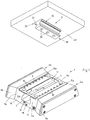
- the Fig. 1 shows the two essential elements of the clamping device in a perspective view.
- the clamping device comprises a chuck 1 and a clamping element 2 which can be clamped in the chuck 1.
- the chuck 1 is usually fixed on the processing table of a processing machine, while the clamping element 2 is fastened on the underside of a pallet.
- the chuck 1 is in a view from above and the clamping element 2 together with the hint drawn workpiece carrier 40 shown in a view from below.
- the chuck 1 is provided with two elongated clamping members, which, however, are not apparent from this illustration.
- the chuck 1 is formed by two substantially identical chuck halves 4a, 4b.
- Each chuck half 4a, 4b is provided with a housing 5a, 5b wherein the two housings 5a, 5b are bolted in the region of their bottom to a housing designated overall by 5.
- Each chuck half 4a, 4b also has a piston housing 8a, 8b, in the interior of which a piston (not shown) is arranged.
- the chuck 1 is provided with an elongated, slot-shaped receiving opening 7 for the elongated clamping element 2.
- a centering element 9 in the form of a resiliently yielding in the Z direction disc 9a on the chuck 1 is arranged.
- the Z direction is that direction which normally runs vertically, ie perpendicular to the surface of the machining table, while the X and Y directions run parallel to the surface of the machining table on which such a chuck 1 is clamped.
- the centering 9a is fixed by means of screws 10 to the housing 5 and the two housing parts 5a, 5b of the chuck 1.
- the centering 9 simultaneously acts as a reinforcement for the two housing parts 5a, 5b.
- an elongated, substantially rectangular centering opening 11 is inserted.
- two mutually parallel side walls 12a, 12b are formed along the longitudinal side of the centering, which are tuned to the respective clamping element 2, that the clamping element 2 is aligned transversely to the longitudinal axis L of the receiving opening 7 when inserted into the receiving opening 7.
- These two side walls 12a, 12b form a kind of tongues, which are resilient in the Z direction resiliently.
- the clamping element 2 is aligned during insertion into the receiving opening 7 in the X or Y direction.
- the clamping element 2 is aligned at insertion on the two side walls 12a, 12b transversely to the longitudinal axis L of the receiving opening 7 and the chuck 1.
- the clamping element 2 is provided for this purpose in the rear or upper region with tapered side surfaces, as will be explained below.
- the Clamping element 2 applies during insertion into the chuck 1 linearly on the centering 9a, which, for example, in terms of a dirt insensitivity benefits, since they act as dirt wiper.
- the chuck 1 On both sides of the centering 9a, the chuck 1 is provided with elongated, elevated bearing surfaces 15a, 15b, which form the Z-support for the workpiece carrier during clamping on the chuck 1. These bearing surfaces 15a, 15b extend parallel to the longitudinal axis L of the receiving opening 7.
- the end face 16 of the chuck 1 open in the bottom region two channels 17, 18, via which compressed air can be introduced.
- the one channel 17 serves to open the chuck, while the other channel 18 is provided for tightening the clamping members.
- the two channels 17, 18 extend on the one hand through the chuck 1 through to the other end face.
- the respective channel with two chuck halves 4a, 4b is connected. In any case, each chuck half 4a, 4b on each end face on a channel for connection to a compressed air line. This training also allows a series connection of several chucks.
- the tensioning element 2 is in the form of an elongated beam which is similar in cross-section to a track rail.
- the clamping element 2 can be tightened on the one hand in the chuck 1; At the same time, it also performs a centering function by having, in addition to clamping surfaces, centering surfaces by means of which it is aligned transversely to the longitudinal axis L of the receiving opening 7 when it is inserted into the chuck 1.
- the clamping element 2 has a flat rear side, which comes to bear on the underside of the workpiece carrier 40 when tightening flat.
- the clamping element 2 is provided with holes 30 for receiving fastening screws.
- the tension member 2 On the front side facing the chuck 1, the tension member 2 is T-shaped, so that a head portion in the form of a projection 32 is formed.
- the clamping element 2 In the area of the back, the clamping element 2 is provided on each longitudinal side with a centering surface 35.
- the respective centering surface 35 is preferably formed in two stages.
- the workpiece carrier 40 comes when tightening the clamping element 2 with its flat bottom on the support surfaces 15a, 15b to the plant.
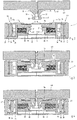
- FIGS. 2 to 4 which show the chuck 1 together with the fixed to a workpiece carrier 40 clamping element 2 in section, in particular the formation of the chuck 1 and its operation when tightening the clamping element 2 is explained in more detail.
- the clamping element 2 is fastened by means of several screws on the underside of the workpiece carrier 40 shown schematically.
- FIG. 2 shows the chuck 1 in the open state together with the not yet placed or clamped workpiece carrier 40
- FIG. 3 the chuck 1 in the open state shown together with the loosely placed thereon workpiece carrier.
- the chuck is shown in a snapshot when clamping the workpiece carrier. Since the chuck 1 consists of two essentially identically designed chuck halves 4a, 4b, which are shown here in mirror image, the elements of one chuck half 4a are provided with identical reference numerals as the corresponding elements of the other chuck half 4b.
- two clamping members 20 are arranged in the form of slides inside the chuck 1.
- the two clamping members 20 are opposite each other, are elongated and arranged parallel to each other.
- the clamping members 20 are integrally formed and designed very robust.
- the two clamping members 20 made of nitrided steel.
- Each clamping member 20 is loaded by means of a plurality of compression springs 25 in the direction of the receiving opening 7, wherein from this illustration only one compression spring 25 per clamping member 20 can be seen.
- the compression springs 25 are supported on the rear side on the piston housing 8a, 8b.
- the respective clamping member 20 is provided with a projection 21, whose underside has a clamping surface 22, by means of which the clamping member 20 can engage a clamping surface 33 on the back of the projection 32 of the clamping element 2 to feed the clamping element 2 and together with the workpiece carrier 40th to tighten on the chuck 1.
- the clamping element 2 is provided along its two longitudinal sides with such a clamping surface 33.
- the two clamping surfaces 33 are each formed by an undercut in the clamping element 2.
- the extension 21 arranged on the clamping surface 22 of the respective clamping member 20 is so matched to the clamping surface 33 of the clamping element 2, that the clamping element 2 by the two clamping members 20 is pulled with a high force down or in the chuck 1.
- the respective clamping member 20 is formed in the form of an elongated slider, this can create a large area along this along the entire length of the clamping element 2 and clamp the workpiece carrier 40 with a high force on the chuck 1, so that the clamping element 2 and thus also the workpiece carrier 40 can accommodate large forces, in particular high lateral forces / can. Furthermore, a recessed in the bottom portion in the housing 5 channel 17 can be seen, the function will be explained later. Instead of a total of two clamping members, two or three clamping members could be provided per side, for example, so that a total of four or six clamping members would be present, this number is by no means to be considered as conclusive.
- the respective clamping member 20 is connected via push rods 36 with a piston 24 arranged on the same plane.
- the respective piston 24 is arranged laterally displaceable in the interior of the associated piston housing 8a, 8b.
- This training allows a compact design with low overall height of the entire chuck 1.
- the two pistons 24 move the associated clamping members 20 independently, which u.a. brings the advantage that the clamping element 2 in the transverse direction does not have to be exactly centered in the chuck. This is an advantage, in particular in the case of large clamping systems with a plurality of chucks, as will be explained below.
- the space 26 between the front of the respective piston 24 and the base of the piston housing 8a, 8b is referred to as a pressure chamber, while the space 27 between the back of the piston 24 and a side housing cover 37 is referred to as Nachspannraum.
- Both the pressure chamber 26 and the Nachspannraum 27 can be applied via internal channels (not shown) with pressure.
- a cable channel 17 can be seen, which, for example, for receiving sensor lines or similar. suitable.
- the compression springs 25 are formed and arranged such that they load the respective piston 24, and thus also the two clamping members 20, in the direction of the receiving opening 7, so that the clamping element 2 is tightened by the force of the springs 25 in the chuck 1 or tightened remains.
- the respective pressure chamber 26 In order to bring the respective piston 24 together with the mechanically coupled clamping member 20 in the position shown here, pushed back, the respective pressure chamber 26 must be pneumatically acted upon. For this purpose, a high pressure in the pressure chamber 26 must be generated so that the force of the force acting on the respective clamping member 20 compression springs, as well as any other compression springs, together with the frictional resistances are overcome.
- the clamping element front part When inserting the clamping element 2 into the receiving opening 7 of the chuck 1, the clamping element front part is first introduced with its two clamping surfaces 33 in the receiving opening 7. At the end of the insertion process then come the centering surfaces 35 of the clamping element 2 on the centering 9a to the plant. In any case, the clamping surfaces 33 of the clamping element 2 are arranged in the insertion direction in front of the centering surfaces 35.
- Fig. 3 shows the chip chuck 1 together with the loosely resting workpiece carrier 40.
- Lose in this context means that the workpiece carrier 40 rests on the chuck 1 only with its own weight, of course, including any workpieces attached thereto.
- the centering surfaces of the clamping element 2 are dimensioned and matched to the centering that the clamping element when inserted into the centering or the receiving opening transversely to its longitudinal axis L (FIG. Fig. 5 ) or transversely to the longitudinal axis of the receiving opening is aligned exactly. Due to the two-stage design of the clamping element arranged centering a coarse and then a fine centering is performed first.
- a small gap remain because the respective clamping element 2 is supported in the Z direction on the centering 9a.
- the centering disk preferably has a thickness of between 2 and 5 millimeters, so that certain centering forces can also be absorbed via the centering disk 9a.
- the positioning of the workpiece carrier in the Z-direction takes place by utilizing the elastic resilience of the centering. This gap is canceled when the clamping element is further pulled under the action of the clamping elements in the chuck. In this case, the position of the clamping element does not change transversely to the longitudinal axis of the receiving opening, since only a very small movement of the workpiece carrier or the clamping element takes place in the Z direction after the loose placing of the workpiece carrier.
- the workpiece carrier 40 moves after aligning the clamping element 2 by a few tenths of a millimeter in the Z direction until it comes to rest on the raised surface portions 15 of the chuck 1.
- the basic principle of such a positioning is from the EP 0 111 092 B2 known.
- the Fig. 4 shows a section through the chuck 1 together with the workpiece carrier 40 and the clamping element 2 attached thereto during the tightening of the workpiece carrier 40.
- additional springs 38 can be seen, which are clamped between the back of the respective piston 24 and the lateral housing cover 37. Although only one additional spring 38 per piston 24 can be seen, 24 more such springs 38 are available for each piston. These additional springs 38 load the piston 24 in the direction of the chuck inside and increase the clamping force of the frictionally connected to the respective piston clamping member 20 in addition to the previously mentioned compression springs 25. By Such additional springs 38, the mechanical clamping force can be increased sustainably. It is understood that the pneumatic pushing back of the respective piston 24 and the force of these auxiliary springs 38 must be overcome.
- the two clamping members 20 can move inwardly into the active or clamping position, the pressure in the pressure chamber 26 is reduced or the pressure chamber 26 is opened to the atmosphere. Under the force of the compression springs 25, 38 then move the two pistons 24 together with the non-positively associated clamping members 20 inside.
- the clamping surface 22 of the respective clamping member 20 bears against the corresponding clamping surface 33 of the clamping element 2 ( Fig. 2 ) and pulls this together with the workpiece carrier 40 in the Z direction down until the workpiece carrier 40 comes to rest on the raised surface portions of the chuck 1.
- the centering disk 9a is elastically deformed in the region of the centering opening in the direction of the inner side of the chuck, as hinted at.
- the Nachspannraum 27 can be pneumatically pressurized.
- the Fig. 5 shows the chuck 1 together with a recorded in the receiving opening 7 clamping element 2 in a view from above.
- the centering opening 11 recessed in the centering disk 9a is significantly longer than the clamping element 2.
- the length of the clamping element 2 is designated A, while the length of the centering opening 11 is designated B.
- the receiving opening 7 extends in the longitudinal direction through the entire chuck 1 and thus of course longer than the clamping element 2.
- both the centering opening 11 and the receiving opening 7 by at least 5% longer than the clamping element. 2 , more preferably at least 10%, most preferably at least 20%.
- Such a design ensures that the clamping element 2 does not have to be inserted centrally or exactly in the center into the chuck 1, but that this in the longitudinal direction, ie in the direction of the longitudinal axis L of the clamping element 2 and the centering 11, certainly displaced by a few millimeters or even a few centimeters into the centering opening 11 and receiving opening 7 of the chuck 1 can be introduced, which is particularly advantageous for large workpiece carriers and clamping systems, as will be explained in more detail below.
- Fig. 6 shows a simplified representation of a chuck half 4b in a view from the inside.
- the workpiece carrier 40 can be seen together with the clamping element 2 arranged thereon and also shown in a simplified manner. From this view, in particular the received in a slide opening 28 of the chuck housing 5 clamping member 20 can be seen.
- the length of the clamping element 2 is again denoted by A, while the length of the clamping member 20 is denoted by C.
- the clamping member 20 is slightly longer than the clamping element 2.
- the clamping device shown forms the basic element for forming a clamping system with which, in particular, large and / or heavy workpieces or workpiece carriers can be clamped in the working area of a processing machine, for example a milling machine, grinding machine, EDM machine or a lathe.
- a processing machine for example a milling machine, grinding machine, EDM machine or a lathe.
- large or very large workpiece carriers are understood to mean workpiece carriers which in at least one direction can have a width or length of approximately one meter and more, and these can also be up to ten meters in size. On such workpiece carriers workpieces with a total weight of up to several thousand kilograms can be attached.
- such a clamping device forms a modular component by means of which large to very large clamping systems can be realized.
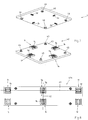
- the Fig. 7 shows such a clamping system having a clamping pedestal 42 and a clamping shell.
- the clamping pedestal 42 includes four chucks 1a-1d while the tensioning upper part comprises a workpiece carrier 40 with four clamping elements 2a-2d arranged thereon.
- the respective chuck is offset by 90 ° with respect to its two adjacent chucks on a schematically indicated machine table 43 of a processing machine (not shown), while the four clamping elements 2a-2d are arranged corresponding to the chucks 1a-1d on the underside of the workpiece carrier 40.
- the clamping system also comprises four pre-centering devices consisting of four centering pins 45 arranged on the machine table 43 and four centering sleeves 46 arranged on the workpiece carrier 40.
- the pre-centering devices serve to ensure that the clamping elements 2a-2d of the workpiece carrier 40 are comparatively when being brought to the clamping base 42 can be easily and quickly aligned with the four chucks 1a-1d. As a result, it is possible to prevent the clamping elements 2a-2d from damaging the chucks 1a-1d if, when the workpiece carrier 40 is lowered, they are not aligned sufficiently precisely with the respective chuck 1a-1d. It should be noted that the workpiece carrier 40, which may well have a weight of several hundred to several thousand kilograms, usually by means of a crane o.ä. moved and placed on the clamping base 42.
- the workpiece carrier 40 alone usually has a weight of at least about 200-300 kilograms and can accommodate a weight up to several thousand kilograms. With insufficient alignment of the workpiece carrier 40 relative to the clamping pedestal 42, the centering pins 45 come to rest on the underside of the workpiece carrier 40 and prevent its further lowering and thus any damage to the chuck 1a-1d.
- Fig. 7 are all four chucks 1a-1d with a centering 9a-9d and all four clamping elements 2a-2d provided with centering surfaces for aligning with the respective centering 9a-9d.
- this is basically a mechanical over-determination in the XY plane, this can be compensated as far as possible by the elastic resilience of the centering.
- Such a design is particularly suitable for small to medium-sized clamping systems.
- Fig. 8 shows an embodiment of a clamping pedestal 42a, which is suitable for large to very large clamping systems.
- the clamping pedestal 42a is a total of six chucks 1 e-1 k provided. Of the six chucks 1 e-1 k aligned on the one hand, the two middle chucks 1g, 1k with each other. On the other hand, the two upper outer chucks 1f, 1h are aligned with each other. The two lower outer chucks 1 e, 1 i are aligned with none of the other chucks 1f, 1 g, 1 h, 1 k.
- not all chucks are provided with a centering disc but only the two middle 1 g, 1k defining the Y direction and the two outer rear ones 1f, 1h defining the X direction.
- the two outer lower chucks 1 e, 1i have no centering; they thus serve only for clamping a corresponding arranged on the pallet clamping element.
- the intersection of the provided by a centering chuck 1f, 1h; 1g, 1k extending axes A1, A2 forms the clamping system zero point N.
- the chuck are arranged at least as far away from each other as possible, so that even the correspondingly attached to the respective workpiece carrier clamping elements can be arranged as far outside on the workpiece carrier.
- Such a clamping pedestal 42a is also suitable for clamping workpiece carriers with four clamping elements. Both workpiece carriers can be used, the clamping elements with the two middle chucks 1g, 1k and either the right 1 e, 1f or left chucks 1 h, 1 i cooperate.
- Such a designed clamping system is on the one hand relatively insensitive with respect to accurate positioning of the clamping elements on the workpiece carrier, as well as with respect to manufacturing tolerances of the clamping elements as well as the centering, as certain inaccuracies can be compensated on the one hand by the spring washers and on the other hand, the described arrangement of the chuck also contributes to the fact that, for example, temperature-induced changes in length of the workpiece carrier can be compensated or recorded.
- chucks could be provided with centering discs.
- the centering surfaces 35 could preferably be omitted in some clamping elements, so that the corresponding clamping elements do not come into contact with the centering disks during clamping on the chuck, but serve only for clamping in the chuck.
- a combination of both is possible by omitting the centering in one or more chucks and the centering surfaces in one or more clamping elements.
- the respective clamping pedestal 42, 42a is additionally provided with elements for detecting the presence of a workpiece carrier.
- elements for detecting the presence of a workpiece carrier For example, commercially available proximity switches can be used as elements, for example on a mechanical, inductive, capacitive, optical or magnetic basis.
- FIG. 9 shows an alternative and particularly preferred embodiment of the chuck 1 in a section.
- the two chuck halves 4a, 4b are connected to one another in the upper region by means of two braces 47, only one of the two braces being apparent from this illustration.
- Each strut consists of a spacer sleeve 48 and a clamping screw 49.
- the chuck 1 is reinforced in both end regions by means of such a strut 47.
- the clear distance between the two struts is greater than the length of a clamping element.
- the clear distance between the two struts is approximately the same size as the length of the recessed into the centering 9a centering 11 ( Fig.
- the two struts are also designed and mounted so that the identical design of the two chuck halves 4a, 4b is maintained.
- clamping systems could be realized in the invention, which are provided with a plurality of distributed on a circle arranged chucks. For example, three, four, five or six chucks could be arranged along a circular line distributed on a clamping pedestal.
Landscapes
- Engineering & Computer Science (AREA)
- Mechanical Engineering (AREA)
- Jigs For Machine Tools (AREA)
Applications Claiming Priority (1)
| Application Number | Priority Date | Filing Date | Title |
|---|---|---|---|
| CH00829/16A CH712703A1 (de) | 2016-06-30 | 2016-06-30 | Spanneinrichtung sowie Spannsystem. |
Publications (2)
| Publication Number | Publication Date |
|---|---|
| EP3263274A1 true EP3263274A1 (fr) | 2018-01-03 |
| EP3263274B1 EP3263274B1 (fr) | 2022-01-12 |
Family
ID=58605985
Family Applications (1)
| Application Number | Title | Priority Date | Filing Date |
|---|---|---|---|
| EP17000673.8A Active EP3263274B1 (fr) | 2016-06-30 | 2017-04-20 | Dispositif de serrage et système de serrage |
Country Status (16)
| Country | Link |
|---|---|
| US (1) | US11065731B2 (fr) |
| EP (1) | EP3263274B1 (fr) |
| JP (1) | JP7126810B2 (fr) |
| KR (1) | KR102251973B1 (fr) |
| CN (1) | CN107553177B (fr) |
| CA (1) | CA2965109C (fr) |
| CH (1) | CH712703A1 (fr) |
| DK (1) | DK3263274T3 (fr) |
| ES (1) | ES2904588T3 (fr) |
| HK (1) | HK1243038A1 (fr) |
| IL (1) | IL252294B (fr) |
| PL (1) | PL3263274T3 (fr) |
| PT (1) | PT3263274T (fr) |
| RU (1) | RU2709126C2 (fr) |
| SG (2) | SG10202010327WA (fr) |
| TW (2) | TWI719197B (fr) |
Cited By (2)
| Publication number | Priority date | Publication date | Assignee | Title |
|---|---|---|---|---|
| CN109108856A (zh) * | 2018-09-29 | 2019-01-01 | 沈阳富创精密设备有限公司 | 一种非标螺钉批量加工工艺 |
| WO2020035102A1 (fr) | 2018-08-16 | 2020-02-20 | Schaeffler Technologies AG & Co. KG | Système de serrage pour une machine de ponçage |
Families Citing this family (15)
| Publication number | Priority date | Publication date | Assignee | Title |
|---|---|---|---|---|
| DE102016219728A1 (de) * | 2016-10-11 | 2018-04-12 | Mag Ias Gmbh | Haltevorrichtung zum Positionieren und Fixieren einer Werkstückadaptervorrichtung und Werkstückadaptervorrichtung zum Positionieren und Fixieren eines Werkstücks mittels einer derartigen Haltevorrichtung sowie Haltevorrichtung-Werkstückadaptervorrichtung-Anordnung |
| TWM573673U (zh) * | 2018-08-28 | 2019-02-01 | 周文祥 | 具簡便定位之交換裝置 |
| EP3769909B1 (fr) * | 2019-07-25 | 2025-12-10 | Maschinenfabrik Berthold Hermle AG | Palette de pièces et système d'usinage |
| CN112091684B (zh) * | 2020-09-09 | 2023-08-08 | 厦门奥拓美科技有限公司 | 自贴合曲面定位柔性夹具 |
| EP4015164A1 (fr) | 2020-12-18 | 2022-06-22 | System 3R International AB | Préhenseur pour un manipulateur |
| JP7624709B2 (ja) * | 2021-03-26 | 2025-01-31 | 三笠産業株式会社 | キャップ付き容器および同容器の組み立て方法 |
| CN113414912B (zh) * | 2021-05-25 | 2022-08-12 | 成都飞机工业(集团)有限责任公司 | 一种用于飞机蒙皮零件加工的柔性工装及其使用方法 |
| CN113664563A (zh) * | 2021-08-20 | 2021-11-19 | 西安飞机工业(集团)有限责任公司 | 一种板料零件的柔性限位装夹结构及柔性限位装夹方法 |
| DE102021127181A1 (de) | 2021-10-20 | 2023-04-20 | Purem GmbH | Wechselträgersystem |
| TWI807951B (zh) * | 2022-08-03 | 2023-07-01 | 宇瞻科技股份有限公司 | 連排物件的夾固裝置 |
| CN116604109B (zh) * | 2023-07-10 | 2024-01-16 | 台州市神鹰机床有限公司 | 水车式双线轨伺服展刀头 |
| DE102023206558A1 (de) * | 2023-07-11 | 2024-07-11 | Carl Zeiss Smt Gmbh | Spannlager, Transportroboter und Prüfsystem |
| CN117245407A (zh) * | 2023-09-26 | 2023-12-19 | 中国铁建重工集团股份有限公司 | 落地式加工系统及其使用方法 |
| JP7619418B1 (ja) | 2023-10-18 | 2025-01-22 | 積水ハウス株式会社 | 測量用治具 |
| JP7619417B1 (ja) | 2023-10-18 | 2025-01-22 | 積水ハウス株式会社 | 測量用治具 |
Citations (10)
| Publication number | Priority date | Publication date | Assignee | Title |
|---|---|---|---|---|
| EP0111092A1 (fr) * | 1982-10-18 | 1984-06-20 | Erowa AG | Dispositif d'accouplement |
| EP0267352A2 (fr) | 1986-10-10 | 1988-05-18 | Büchler B-SET AG | Dispositif pour fixer d'une manière réitérable et très précise la position dans l'espace d'un premier objet par rapport à d'autres objets |
| EP0403428A2 (fr) | 1989-06-10 | 1990-12-19 | Erowa AG | Dispositif pour l'abloquage indixé d'une pièce sur une table d'usinage |
| EP0614725A2 (fr) | 1993-03-09 | 1994-09-14 | Erowa AG | Dispositif pour l'abloquage indixé d'une pièce au poste de travail d'une machine d'usinage |
| EP0624428A2 (fr) * | 1993-05-04 | 1994-11-17 | Erowa AG | Dispositif pour le blocage indexé d'une pièce à un poste de travail d'une machine d'usinage |
| EP0694364A1 (fr) * | 1994-07-27 | 1996-01-31 | Campro Tooling AB | Dispositif de serrage |
| DE29802835U1 (de) * | 1998-02-19 | 1998-08-13 | System 3R International AB, Vällingby | Kupplung mit zwei Kupplungsorganen und einer Spannvorrichtung |
| EP1595641A1 (fr) | 2004-04-22 | 2005-11-16 | Erowa AG | Dispositif de serrage avec mandrin et palette fixé de façon amovible sur le mandrin. |
| EP2052808A1 (fr) * | 2007-10-22 | 2009-04-29 | Erowa AG | Dispositif de serrage doté d'un mandrin destiné à la fixation amovible d'un support de pièces à usiner |
| DE102008045620A1 (de) * | 2008-07-22 | 2010-01-28 | Erowa Ag | Spanneinrichtung |
Family Cites Families (17)
| Publication number | Priority date | Publication date | Assignee | Title |
|---|---|---|---|---|
| US973A (en) * | 1838-10-08 | Aimttlar saw fob | ||
| SU524670A1 (ru) * | 1975-08-07 | 1976-08-15 | Экспериментальный научно-исследовательский институт металлорежущих станков | Устройство дл закреплени приспособлени -спутника |
| IE47522B1 (en) * | 1977-07-16 | 1984-04-18 | Walton Mole Co | Apparatus for cleaining and descaling the exterior of elongate cylindrical structures such as pipe lines and jackets of off-shore oil rigs |
| CH675150A5 (en) * | 1982-10-18 | 1990-08-31 | Erowa Ag | Clutch for e.g. machine tool |
| SU1528637A1 (ru) * | 1987-10-26 | 1989-12-15 | Новосибирское производственное объединение "Тяжстанкогидропресс" | Устройство дл установки крупногабаритной палеты на поворотном столе станка |
| JPH04348835A (ja) * | 1991-05-27 | 1992-12-03 | Sodick Co Ltd | パレットの位置決めクランプ装置 |
| DE19636375A1 (de) * | 1996-09-09 | 1998-03-12 | Emil Stark | Schnellverschluß für eine Palette unter Späneflug |
| DE59708679D1 (de) * | 1997-12-11 | 2002-12-12 | Parotec Ag Flawil | Einheit zum lösbaren Verbinden von Teilen einer Palettiervorrichtung und Palettiervorrichtung |
| TW592882B (en) * | 2001-12-19 | 2004-06-21 | Erowa Ag | Clamping apparatus with a clamping chuck and a work piece carrier releasable connectable thereto |
| DE50300015D1 (de) | 2002-03-11 | 2004-07-01 | Erowa Ag Reinach | Spanneinrichtung mit einem Spannfutter und einem darin festspannbaren Spannzapfen |
| JP2010099785A (ja) | 2008-10-24 | 2010-05-06 | Pascal Engineering Corp | ワークパレット位置決め固定機構 |
| RU112653U1 (ru) * | 2011-06-10 | 2012-01-20 | Общество с ограниченной ответственностью "РАДОП" | Устройство для очистки наружной поверхности труб |
| CZ309713B6 (cs) * | 2013-08-20 | 2023-08-16 | Erowa Ag | Upínací zařízení |
| DE102013226412B4 (de) * | 2013-12-18 | 2021-11-18 | Schunk Gmbh & Co. Kg Spann- Und Greiftechnik | Spannmodul, insbesondere Nullpunktspannmodul und zugehöriges Spannsystem |
| CN204295371U (zh) * | 2014-11-21 | 2015-04-29 | 西安斯诺机械智能科技有限公司 | 防错柔性快速定位强力夹紧装置 |
| US9604330B2 (en) * | 2015-03-12 | 2017-03-28 | Jia Sin Precision Co., Ltd. | Positioning block structure for machining fixture |
| CN204843650U (zh) * | 2015-08-13 | 2015-12-09 | 锦州益日隆工艺装备有限公司 | 短型大口径斜楔式定心夹具 |
-
2016
- 2016-06-30 CH CH00829/16A patent/CH712703A1/de not_active Application Discontinuation
-
2017
- 2017-04-13 US US15/486,662 patent/US11065731B2/en not_active Expired - Fee Related
- 2017-04-13 SG SG10202010327WA patent/SG10202010327WA/en unknown
- 2017-04-13 SG SG10201703091SA patent/SG10201703091SA/en unknown
- 2017-04-20 EP EP17000673.8A patent/EP3263274B1/fr active Active
- 2017-04-20 PT PT170006738T patent/PT3263274T/pt unknown
- 2017-04-20 DK DK17000673.8T patent/DK3263274T3/da active
- 2017-04-20 PL PL17000673.8T patent/PL3263274T3/pl unknown
- 2017-04-20 ES ES17000673T patent/ES2904588T3/es active Active
- 2017-04-24 TW TW106113586A patent/TWI719197B/zh not_active IP Right Cessation
- 2017-04-24 TW TW109142220A patent/TWI738579B/zh not_active IP Right Cessation
- 2017-04-26 CA CA2965109A patent/CA2965109C/fr active Active
- 2017-05-15 IL IL252294A patent/IL252294B/en unknown
- 2017-06-05 JP JP2017110749A patent/JP7126810B2/ja active Active
- 2017-06-27 KR KR1020170081303A patent/KR102251973B1/ko not_active Expired - Fee Related
- 2017-06-29 RU RU2017123018A patent/RU2709126C2/ru active
- 2017-06-29 CN CN201710514795.1A patent/CN107553177B/zh active Active
-
2018
- 2018-02-23 HK HK18102600.8A patent/HK1243038A1/zh unknown
Patent Citations (11)
| Publication number | Priority date | Publication date | Assignee | Title |
|---|---|---|---|---|
| EP0111092A1 (fr) * | 1982-10-18 | 1984-06-20 | Erowa AG | Dispositif d'accouplement |
| EP0111092B2 (fr) | 1982-10-18 | 1992-11-25 | Erowa AG | Dispositif d'accouplement |
| EP0267352A2 (fr) | 1986-10-10 | 1988-05-18 | Büchler B-SET AG | Dispositif pour fixer d'une manière réitérable et très précise la position dans l'espace d'un premier objet par rapport à d'autres objets |
| EP0403428A2 (fr) | 1989-06-10 | 1990-12-19 | Erowa AG | Dispositif pour l'abloquage indixé d'une pièce sur une table d'usinage |
| EP0614725A2 (fr) | 1993-03-09 | 1994-09-14 | Erowa AG | Dispositif pour l'abloquage indixé d'une pièce au poste de travail d'une machine d'usinage |
| EP0624428A2 (fr) * | 1993-05-04 | 1994-11-17 | Erowa AG | Dispositif pour le blocage indexé d'une pièce à un poste de travail d'une machine d'usinage |
| EP0694364A1 (fr) * | 1994-07-27 | 1996-01-31 | Campro Tooling AB | Dispositif de serrage |
| DE29802835U1 (de) * | 1998-02-19 | 1998-08-13 | System 3R International AB, Vällingby | Kupplung mit zwei Kupplungsorganen und einer Spannvorrichtung |
| EP1595641A1 (fr) | 2004-04-22 | 2005-11-16 | Erowa AG | Dispositif de serrage avec mandrin et palette fixé de façon amovible sur le mandrin. |
| EP2052808A1 (fr) * | 2007-10-22 | 2009-04-29 | Erowa AG | Dispositif de serrage doté d'un mandrin destiné à la fixation amovible d'un support de pièces à usiner |
| DE102008045620A1 (de) * | 2008-07-22 | 2010-01-28 | Erowa Ag | Spanneinrichtung |
Cited By (3)
| Publication number | Priority date | Publication date | Assignee | Title |
|---|---|---|---|---|
| WO2020035102A1 (fr) | 2018-08-16 | 2020-02-20 | Schaeffler Technologies AG & Co. KG | Système de serrage pour une machine de ponçage |
| US12070804B2 (en) | 2018-08-16 | 2024-08-27 | Schaeffler Technologies AG & Co. KG | Mounting system for a grinding machine |
| CN109108856A (zh) * | 2018-09-29 | 2019-01-01 | 沈阳富创精密设备有限公司 | 一种非标螺钉批量加工工艺 |
Also Published As
| Publication number | Publication date |
|---|---|
| EP3263274B1 (fr) | 2022-01-12 |
| KR20180003450A (ko) | 2018-01-09 |
| CA2965109C (fr) | 2023-09-05 |
| RU2017123018A3 (fr) | 2019-08-15 |
| JP2018001399A (ja) | 2018-01-11 |
| KR102251973B1 (ko) | 2021-05-17 |
| CH712703A1 (de) | 2018-01-15 |
| TW202114801A (zh) | 2021-04-16 |
| HK1243038A1 (zh) | 2018-07-06 |
| PL3263274T3 (pl) | 2022-07-18 |
| ES2904588T3 (es) | 2022-04-05 |
| US11065731B2 (en) | 2021-07-20 |
| CN107553177B (zh) | 2024-05-03 |
| TWI738579B (zh) | 2021-09-01 |
| SG10201703091SA (en) | 2018-01-30 |
| DK3263274T3 (da) | 2022-03-14 |
| SG10202010327WA (en) | 2020-11-27 |
| IL252294A0 (en) | 2017-07-31 |
| RU2709126C2 (ru) | 2019-12-16 |
| TW201806690A (zh) | 2018-03-01 |
| RU2017123018A (ru) | 2018-12-29 |
| PT3263274T (pt) | 2022-01-27 |
| CA2965109A1 (fr) | 2017-12-30 |
| TWI719197B (zh) | 2021-02-21 |
| IL252294B (en) | 2022-01-01 |
| JP7126810B2 (ja) | 2022-08-29 |
| CN107553177A (zh) | 2018-01-09 |
| US20180001427A1 (en) | 2018-01-04 |
Similar Documents
| Publication | Publication Date | Title |
|---|---|---|
| EP3263274B1 (fr) | Dispositif de serrage et système de serrage | |
| EP0614725B1 (fr) | Dispositif pour l'abloquage indixé d'une pièce au poste de travail d'une machine d'usinage | |
| EP2085177B1 (fr) | Dispositif de serrage pour le serrage fixe de pièces usinées | |
| AT514431B1 (de) | Spanneinrichtung | |
| EP3983169B1 (fr) | Dispositif de serrage et dispositif de maintien de pièce comprenant un dispositif de serrage | |
| EP0922529A1 (fr) | Unité pour connecter temporairement des parties d'un dispositif de palletisation et un dispositif de palettisation | |
| EP0818270A1 (fr) | Dispositif de serrage et dispositif pour le blocage indexé d'une pièce de travail ou d'un outil | |
| EP1813381A1 (fr) | Dispositif de serrage doté d'un mandrin pour le serrage fixe d'un élément de serrage | |
| EP0624428A2 (fr) | Dispositif pour le blocage indexé d'une pièce à un poste de travail d'une machine d'usinage | |
| EP4194141A1 (fr) | Dispositif de serrage | |
| DE102011054063B4 (de) | Antriebsvorrichtung für ein Stützteil zum Abstützen eines Werkstücks | |
| EP3393693B1 (fr) | Mécanisme à clavette | |
| EP2918379A1 (fr) | Dispositif d'embrayage pour un appareil de manipulation | |
| EP1955816A2 (fr) | Dispositif de serrage | |
| EP0450383A1 (fr) | Dispositif de serrage et de centrage | |
| EP2658708B1 (fr) | Presse à poudre ou adaptateur de presse à poudre et procédé de fonctionnement d'une presse à poudre | |
| EP1140415A1 (fr) | Dispositif pour serrer et souder des toles | |
| EP0249021B1 (fr) | Système de centrage et de serrage | |
| DE102016012169A1 (de) | Spannvorrichtung | |
| EP3395496A1 (fr) | Unité de serrage pourvue de module de serrage et système de serrage | |
| DE2851700C2 (de) | Zentrier- und Spannvorrichtung für Werkstückträger (Paletten) | |
| EP3366417B1 (fr) | Boulon de tension d'un système de serrage | |
| EP1632308A1 (fr) | Guidage linéaire avec deux rails de guidage parallèles et procédé pour sa fabrication | |
| DE3400813C2 (fr) | ||
| EP0900628A2 (fr) | Sytème de raccord rapide |
Legal Events
| Date | Code | Title | Description |
|---|---|---|---|
| PUAI | Public reference made under article 153(3) epc to a published international application that has entered the european phase |
Free format text: ORIGINAL CODE: 0009012 |
|
| STAA | Information on the status of an ep patent application or granted ep patent |
Free format text: STATUS: REQUEST FOR EXAMINATION WAS MADE |
|
| 17P | Request for examination filed |
Effective date: 20170420 |
|
| AK | Designated contracting states |
Kind code of ref document: A1 Designated state(s): AL AT BE BG CH CY CZ DE DK EE ES FI FR GB GR HR HU IE IS IT LI LT LU LV MC MK MT NL NO PL PT RO RS SE SI SK SM TR |
|
| AX | Request for extension of the european patent |
Extension state: BA ME |
|
| STAA | Information on the status of an ep patent application or granted ep patent |
Free format text: STATUS: EXAMINATION IS IN PROGRESS |
|
| 17Q | First examination report despatched |
Effective date: 20200305 |
|
| GRAP | Despatch of communication of intention to grant a patent |
Free format text: ORIGINAL CODE: EPIDOSNIGR1 |
|
| STAA | Information on the status of an ep patent application or granted ep patent |
Free format text: STATUS: GRANT OF PATENT IS INTENDED |
|
| INTG | Intention to grant announced |
Effective date: 20211026 |
|
| GRAS | Grant fee paid |
Free format text: ORIGINAL CODE: EPIDOSNIGR3 |
|
| GRAA | (expected) grant |
Free format text: ORIGINAL CODE: 0009210 |
|
| STAA | Information on the status of an ep patent application or granted ep patent |
Free format text: STATUS: THE PATENT HAS BEEN GRANTED |
|
| AK | Designated contracting states |
Kind code of ref document: B1 Designated state(s): AL AT BE BG CH CY CZ DE DK EE ES FI FR GB GR HR HU IE IS IT LI LT LU LV MC MK MT NL NO PL PT RO RS SE SI SK SM TR |
|
| REG | Reference to a national code |
Ref country code: GB Ref legal event code: FG4D Free format text: NOT ENGLISH |
|
| REG | Reference to a national code |
Ref country code: CH Ref legal event code: EP |
|
| REG | Reference to a national code |
Ref country code: PT Ref legal event code: SC4A Ref document number: 3263274 Country of ref document: PT Date of ref document: 20220127 Kind code of ref document: T Free format text: AVAILABILITY OF NATIONAL TRANSLATION Effective date: 20220121 Ref country code: DE Ref legal event code: R096 Ref document number: 502017012426 Country of ref document: DE |
|
| REG | Reference to a national code |
Ref country code: IE Ref legal event code: FG4D Free format text: LANGUAGE OF EP DOCUMENT: GERMAN |
|
| REG | Reference to a national code |
Ref country code: AT Ref legal event code: REF Ref document number: 1462047 Country of ref document: AT Kind code of ref document: T Effective date: 20220215 |
|
| REG | Reference to a national code |
Ref country code: FI Ref legal event code: FGE Ref country code: NL Ref legal event code: FP |
|
| REG | Reference to a national code |
Ref country code: DK Ref legal event code: T3 Effective date: 20220307 |
|
| REG | Reference to a national code |
Ref country code: ES Ref legal event code: FG2A Ref document number: 2904588 Country of ref document: ES Kind code of ref document: T3 Effective date: 20220405 Ref country code: SE Ref legal event code: TRGR |
|
| REG | Reference to a national code |
Ref country code: LT Ref legal event code: MG9D |
|
| PG25 | Lapsed in a contracting state [announced via postgrant information from national office to epo] |
Ref country code: RS Free format text: LAPSE BECAUSE OF FAILURE TO SUBMIT A TRANSLATION OF THE DESCRIPTION OR TO PAY THE FEE WITHIN THE PRESCRIBED TIME-LIMIT Effective date: 20220112 Ref country code: NO Free format text: LAPSE BECAUSE OF FAILURE TO SUBMIT A TRANSLATION OF THE DESCRIPTION OR TO PAY THE FEE WITHIN THE PRESCRIBED TIME-LIMIT Effective date: 20220412 Ref country code: LT Free format text: LAPSE BECAUSE OF FAILURE TO SUBMIT A TRANSLATION OF THE DESCRIPTION OR TO PAY THE FEE WITHIN THE PRESCRIBED TIME-LIMIT Effective date: 20220112 Ref country code: HR Free format text: LAPSE BECAUSE OF FAILURE TO SUBMIT A TRANSLATION OF THE DESCRIPTION OR TO PAY THE FEE WITHIN THE PRESCRIBED TIME-LIMIT Effective date: 20220112 Ref country code: BG Free format text: LAPSE BECAUSE OF FAILURE TO SUBMIT A TRANSLATION OF THE DESCRIPTION OR TO PAY THE FEE WITHIN THE PRESCRIBED TIME-LIMIT Effective date: 20220412 |
|
| PG25 | Lapsed in a contracting state [announced via postgrant information from national office to epo] |
Ref country code: LV Free format text: LAPSE BECAUSE OF FAILURE TO SUBMIT A TRANSLATION OF THE DESCRIPTION OR TO PAY THE FEE WITHIN THE PRESCRIBED TIME-LIMIT Effective date: 20220112 Ref country code: GR Free format text: LAPSE BECAUSE OF FAILURE TO SUBMIT A TRANSLATION OF THE DESCRIPTION OR TO PAY THE FEE WITHIN THE PRESCRIBED TIME-LIMIT Effective date: 20220413 |
|
| PG25 | Lapsed in a contracting state [announced via postgrant information from national office to epo] |
Ref country code: IS Free format text: LAPSE BECAUSE OF FAILURE TO SUBMIT A TRANSLATION OF THE DESCRIPTION OR TO PAY THE FEE WITHIN THE PRESCRIBED TIME-LIMIT Effective date: 20220512 |
|
| REG | Reference to a national code |
Ref country code: DE Ref legal event code: R097 Ref document number: 502017012426 Country of ref document: DE |
|
| PG25 | Lapsed in a contracting state [announced via postgrant information from national office to epo] |
Ref country code: SM Free format text: LAPSE BECAUSE OF FAILURE TO SUBMIT A TRANSLATION OF THE DESCRIPTION OR TO PAY THE FEE WITHIN THE PRESCRIBED TIME-LIMIT Effective date: 20220112 Ref country code: SK Free format text: LAPSE BECAUSE OF FAILURE TO SUBMIT A TRANSLATION OF THE DESCRIPTION OR TO PAY THE FEE WITHIN THE PRESCRIBED TIME-LIMIT Effective date: 20220112 Ref country code: RO Free format text: LAPSE BECAUSE OF FAILURE TO SUBMIT A TRANSLATION OF THE DESCRIPTION OR TO PAY THE FEE WITHIN THE PRESCRIBED TIME-LIMIT Effective date: 20220112 Ref country code: EE Free format text: LAPSE BECAUSE OF FAILURE TO SUBMIT A TRANSLATION OF THE DESCRIPTION OR TO PAY THE FEE WITHIN THE PRESCRIBED TIME-LIMIT Effective date: 20220112 |
|
| PLBE | No opposition filed within time limit |
Free format text: ORIGINAL CODE: 0009261 |
|
| STAA | Information on the status of an ep patent application or granted ep patent |
Free format text: STATUS: NO OPPOSITION FILED WITHIN TIME LIMIT |
|
| PG25 | Lapsed in a contracting state [announced via postgrant information from national office to epo] |
Ref country code: AL Free format text: LAPSE BECAUSE OF FAILURE TO SUBMIT A TRANSLATION OF THE DESCRIPTION OR TO PAY THE FEE WITHIN THE PRESCRIBED TIME-LIMIT Effective date: 20220112 |
|
| 26N | No opposition filed |
Effective date: 20221013 |
|
| REG | Reference to a national code |
Ref country code: BE Ref legal event code: MM Effective date: 20220430 |
|
| PG25 | Lapsed in a contracting state [announced via postgrant information from national office to epo] |
Ref country code: MC Free format text: LAPSE BECAUSE OF FAILURE TO SUBMIT A TRANSLATION OF THE DESCRIPTION OR TO PAY THE FEE WITHIN THE PRESCRIBED TIME-LIMIT Effective date: 20220112 Ref country code: LU Free format text: LAPSE BECAUSE OF NON-PAYMENT OF DUE FEES Effective date: 20220420 |
|
| PG25 | Lapsed in a contracting state [announced via postgrant information from national office to epo] |
Ref country code: SI Free format text: LAPSE BECAUSE OF FAILURE TO SUBMIT A TRANSLATION OF THE DESCRIPTION OR TO PAY THE FEE WITHIN THE PRESCRIBED TIME-LIMIT Effective date: 20220112 Ref country code: BE Free format text: LAPSE BECAUSE OF NON-PAYMENT OF DUE FEES Effective date: 20220430 |
|
| PG25 | Lapsed in a contracting state [announced via postgrant information from national office to epo] |
Ref country code: IE Free format text: LAPSE BECAUSE OF NON-PAYMENT OF DUE FEES Effective date: 20220420 |
|
| PGFP | Annual fee paid to national office [announced via postgrant information from national office to epo] |
Ref country code: NL Payment date: 20230419 Year of fee payment: 7 |
|
| PGFP | Annual fee paid to national office [announced via postgrant information from national office to epo] |
Ref country code: PT Payment date: 20230406 Year of fee payment: 7 Ref country code: DK Payment date: 20230421 Year of fee payment: 7 Ref country code: CZ Payment date: 20230412 Year of fee payment: 7 |
|
| PGFP | Annual fee paid to national office [announced via postgrant information from national office to epo] |
Ref country code: PL Payment date: 20230406 Year of fee payment: 7 Ref country code: FI Payment date: 20230419 Year of fee payment: 7 Ref country code: AT Payment date: 20230420 Year of fee payment: 7 |
|
| PGFP | Annual fee paid to national office [announced via postgrant information from national office to epo] |
Ref country code: GB Payment date: 20230419 Year of fee payment: 7 |
|
| REG | Reference to a national code |
Ref country code: DE Ref legal event code: R082 Ref document number: 502017012426 Country of ref document: DE Representative=s name: PUSCHMANN BORCHERT KAISER KLETTNER PATENTANWAE, DE Ref country code: DE Ref legal event code: R082 Ref document number: 502017012426 Country of ref document: DE Representative=s name: PATCARE PATENTANWAELTE PARTNERSCHAFT MBB, DE |
|
| PG25 | Lapsed in a contracting state [announced via postgrant information from national office to epo] |
Ref country code: HU Free format text: LAPSE BECAUSE OF FAILURE TO SUBMIT A TRANSLATION OF THE DESCRIPTION OR TO PAY THE FEE WITHIN THE PRESCRIBED TIME-LIMIT; INVALID AB INITIO Effective date: 20170420 |
|
| PG25 | Lapsed in a contracting state [announced via postgrant information from national office to epo] |
Ref country code: MK Free format text: LAPSE BECAUSE OF FAILURE TO SUBMIT A TRANSLATION OF THE DESCRIPTION OR TO PAY THE FEE WITHIN THE PRESCRIBED TIME-LIMIT Effective date: 20220112 Ref country code: CY Free format text: LAPSE BECAUSE OF FAILURE TO SUBMIT A TRANSLATION OF THE DESCRIPTION OR TO PAY THE FEE WITHIN THE PRESCRIBED TIME-LIMIT Effective date: 20220112 |
|
| PG25 | Lapsed in a contracting state [announced via postgrant information from national office to epo] |
Ref country code: TR Free format text: LAPSE BECAUSE OF FAILURE TO SUBMIT A TRANSLATION OF THE DESCRIPTION OR TO PAY THE FEE WITHIN THE PRESCRIBED TIME-LIMIT Effective date: 20220112 |
|
| PGFP | Annual fee paid to national office [announced via postgrant information from national office to epo] |
Ref country code: ES Payment date: 20240524 Year of fee payment: 8 |
|
| PGFP | Annual fee paid to national office [announced via postgrant information from national office to epo] |
Ref country code: IT Payment date: 20240419 Year of fee payment: 8 Ref country code: FR Payment date: 20240425 Year of fee payment: 8 |
|
| PG25 | Lapsed in a contracting state [announced via postgrant information from national office to epo] |
Ref country code: MT Free format text: LAPSE BECAUSE OF FAILURE TO SUBMIT A TRANSLATION OF THE DESCRIPTION OR TO PAY THE FEE WITHIN THE PRESCRIBED TIME-LIMIT Effective date: 20220112 |
|
| REG | Reference to a national code |
Ref country code: DK Ref legal event code: EBP Effective date: 20240430 |
|
| REG | Reference to a national code |
Ref country code: NL Ref legal event code: MM Effective date: 20240501 |
|
| PG25 | Lapsed in a contracting state [announced via postgrant information from national office to epo] |
Ref country code: PT Free format text: LAPSE BECAUSE OF NON-PAYMENT OF DUE FEES Effective date: 20241021 |
|
| REG | Reference to a national code |
Ref country code: AT Ref legal event code: MM01 Ref document number: 1462047 Country of ref document: AT Kind code of ref document: T Effective date: 20240420 |
|
| GBPC | Gb: european patent ceased through non-payment of renewal fee |
Effective date: 20240420 |
|
| PG25 | Lapsed in a contracting state [announced via postgrant information from national office to epo] |
Ref country code: PT Free format text: LAPSE BECAUSE OF NON-PAYMENT OF DUE FEES Effective date: 20241021 |
|
| PG25 | Lapsed in a contracting state [announced via postgrant information from national office to epo] |
Ref country code: NL Free format text: LAPSE BECAUSE OF NON-PAYMENT OF DUE FEES Effective date: 20240501 Ref country code: FI Free format text: LAPSE BECAUSE OF NON-PAYMENT OF DUE FEES Effective date: 20240420 |
|
| PG25 | Lapsed in a contracting state [announced via postgrant information from national office to epo] |
Ref country code: GB Free format text: LAPSE BECAUSE OF NON-PAYMENT OF DUE FEES Effective date: 20240420 |
|
| PG25 | Lapsed in a contracting state [announced via postgrant information from national office to epo] |
Ref country code: AT Free format text: LAPSE BECAUSE OF NON-PAYMENT OF DUE FEES Effective date: 20240420 |
|
| PG25 | Lapsed in a contracting state [announced via postgrant information from national office to epo] |
Ref country code: CZ Free format text: LAPSE BECAUSE OF NON-PAYMENT OF DUE FEES Effective date: 20240420 |
|
| PG25 | Lapsed in a contracting state [announced via postgrant information from national office to epo] |
Ref country code: NL Free format text: LAPSE BECAUSE OF NON-PAYMENT OF DUE FEES Effective date: 20240501 Ref country code: GB Free format text: LAPSE BECAUSE OF NON-PAYMENT OF DUE FEES Effective date: 20240420 Ref country code: FI Free format text: LAPSE BECAUSE OF NON-PAYMENT OF DUE FEES Effective date: 20240420 Ref country code: CZ Free format text: LAPSE BECAUSE OF NON-PAYMENT OF DUE FEES Effective date: 20240420 Ref country code: AT Free format text: LAPSE BECAUSE OF NON-PAYMENT OF DUE FEES Effective date: 20240420 |
|
| PG25 | Lapsed in a contracting state [announced via postgrant information from national office to epo] |
Ref country code: DK Free format text: LAPSE BECAUSE OF NON-PAYMENT OF DUE FEES Effective date: 20240430 |
|
| PGFP | Annual fee paid to national office [announced via postgrant information from national office to epo] |
Ref country code: DE Payment date: 20250422 Year of fee payment: 9 |
|
| PGFP | Annual fee paid to national office [announced via postgrant information from national office to epo] |
Ref country code: CH Payment date: 20250501 Year of fee payment: 9 |
|
| PGFP | Annual fee paid to national office [announced via postgrant information from national office to epo] |
Ref country code: SE Payment date: 20250429 Year of fee payment: 9 |
|
| PG25 | Lapsed in a contracting state [announced via postgrant information from national office to epo] |
Ref country code: PL Free format text: LAPSE BECAUSE OF FAILURE TO SUBMIT A TRANSLATION OF THE DESCRIPTION OR TO PAY THE FEE WITHIN THE PRESCRIBED TIME-LIMIT Effective date: 20240420 |
|
| PG25 | Lapsed in a contracting state [announced via postgrant information from national office to epo] |
Ref country code: PL Free format text: LAPSE BECAUSE OF NON-PAYMENT OF DUE FEES Effective date: 20240420 |
|
| PG25 | Lapsed in a contracting state [announced via postgrant information from national office to epo] |
Ref country code: FR Free format text: LAPSE BECAUSE OF NON-PAYMENT OF DUE FEES Effective date: 20250430 |
|
| REG | Reference to a national code |
Ref country code: CH Ref legal event code: R17 Free format text: ST27 STATUS EVENT CODE: U-0-0-R10-R17 (AS PROVIDED BY THE NATIONAL OFFICE) Effective date: 20260410 |
|
| PG25 | Lapsed in a contracting state [announced via postgrant information from national office to epo] |
Ref country code: IT Free format text: LAPSE BECAUSE OF NON-PAYMENT OF DUE FEES Effective date: 20250420 |
|
| REG | Reference to a national code |
Ref country code: CH Ref legal event code: U11 Free format text: ST27 STATUS EVENT CODE: U-0-0-U10-U11 (AS PROVIDED BY THE NATIONAL OFFICE) Effective date: 20260501 |