EP0403796B1 - Outil électrique pour enfoncer - Google Patents
Outil électrique pour enfoncer Download PDFInfo
- Publication number
- EP0403796B1 EP0403796B1 EP90109201A EP90109201A EP0403796B1 EP 0403796 B1 EP0403796 B1 EP 0403796B1 EP 90109201 A EP90109201 A EP 90109201A EP 90109201 A EP90109201 A EP 90109201A EP 0403796 B1 EP0403796 B1 EP 0403796B1
- Authority
- EP
- European Patent Office
- Prior art keywords
- switch
- driving
- circuit
- nose
- operated
- Prior art date
- Legal status (The legal status is an assumption and is not a legal conclusion. Google has not performed a legal analysis and makes no representation as to the accuracy of the status listed.)
- Expired - Lifetime
Links
- 230000001960 triggered effect Effects 0.000 claims description 4
- 238000010304 firing Methods 0.000 claims 5
- 230000003213 activating effect Effects 0.000 claims 1
- 238000000034 method Methods 0.000 description 2
- 230000005540 biological transmission Effects 0.000 description 1
- 230000003628 erosive effect Effects 0.000 description 1
- 238000007654 immersion Methods 0.000 description 1
- 230000002028 premature Effects 0.000 description 1
- 230000001629 suppression Effects 0.000 description 1
- 238000003466 welding Methods 0.000 description 1
Images

Classifications
-
- H—ELECTRICITY
- H01—ELECTRIC ELEMENTS
- H01F—MAGNETS; INDUCTANCES; TRANSFORMERS; SELECTION OF MATERIALS FOR THEIR MAGNETIC PROPERTIES
- H01F7/00—Magnets
- H01F7/06—Electromagnets; Actuators including electromagnets
- H01F7/064—Circuit arrangements for actuating electromagnets
-
- B—PERFORMING OPERATIONS; TRANSPORTING
- B25—HAND TOOLS; PORTABLE POWER-DRIVEN TOOLS; MANIPULATORS
- B25C—HAND-HELD NAILING OR STAPLING TOOLS; MANUALLY OPERATED PORTABLE STAPLING TOOLS
- B25C1/00—Hand-held nailing tools; Nail feeding devices
- B25C1/06—Hand-held nailing tools; Nail feeding devices operated by electric power
Definitions
- the invention is based on a driving tool according to the preamble of claim 1.
- a driving tool is already known, in which a blow is triggered by a switch when it is simultaneously operated by a lever and a switch lever in the handle and by mechanical levers the movable magazine is activated. Because of the strong return stroke forces in the driving tools, if the driving tool is weakly pressed against the workpiece during the driving process, the magazine nose can be lifted off the workpiece and the current flow through the magnetic coil can be interrupted. This can lead to premature erosion of the switching contacts and possibly even welding of the contacts and the need for additional interference suppression measures.
- the driving tool according to the invention with the characterizing features of claim 1 has the advantage that the driving process is no longer influenced by the state of the switch actuated by the magazine as soon as the driver blow has been triggered.
- the Current cannot flow through the solenoid by the switch. This also increases the service life of the switch and the entire driving tool.
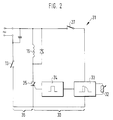
- Figure 1 shows a longitudinal section through a driving tool and Figure 2 shows a simplified control circuit.
- the individual parts of the driving tool 10 according to the invention correspond, insofar as they match, to those from DE 35 43 373 A1.
- the housing 11 of the driving tool 10 has a handle 12.
- a switch 13 is located therein, which is located in the power supply circuit of a magnetic coil 15 and can be operated manually with a pushbutton 16.
- a plunger magnet 19 acting on a driver 18 is arranged within the magnet coil 15.
- the driver 18 is longitudinally displaceable within an ejection channel 20 in the head 21 of a staple magazine 22.
- a nose 23 on the head 21 projects beyond the underside of the magazine 22.
- the magazine 22 is movably supported relative to the housing 11 with the interposition of a spring 24. It acts as a switch button 25 via a lever 26 on a trigger switch 27.
- the lug 23 it is also possible for the lug 23 to be designed as a feeler pin movable in the direction of the discharge channel 20 and to serve as a switching element, the magazine 22 being firmly connected to the housing 11.
- the nose 23 can of course also act directly on the switch 27 without lever transmission.
- the trigger switch 27 is located electrically in an ignition circuit 30 of a control circuit 31 shown in simplified form in FIG. 2, which is connected to an AC voltage (mains voltage 220V) and regulates the power supply to the magnetic coil 15.
- the ignition circuit there is also an impact strength regulator 32, a trigger circuit 33, a pulse shaper 34 and a thyristor 35.
- voltage is applied to the trigger circuit 33 and it gives a pulse corresponding to the position of the impact strength potentiometer 32 to the pulse shaper 34.
- the transformed pulse is passed on to the thyristor 35, so that it becomes conductive and closes the load circuit 36 for supplying power to the magnetic coil 15.
- the solenoid is live for up to 10 milliseconds.
- the thyristor 35 is not conductive and the load circuit 36 is de-energized again.
- a renewed ignition of the thyristor can only take place after opening at least one of the two switches 13 or 27 by subsequently switching both switches back into the closed state at the same time.
- one of the switches 13, 27 can be operated continuously and only the other trigger the switching pulse.
- a very short voltage pulse is sufficient to activate the ignition circuit 30. Opening or closing the switch 27 e.g. when the switch button 25 bounces, the power supply to the magnetic coil 15 does not affect the load circuit closed by the switch 13, since the switch 27 only acts on the trigger circuit 33 which is insensitive in this respect.
- the mechanical sequence of a driver blow occurs in a known manner in such a way that the plunger magnet 19 is attracted by the magnet coil 15 and accelerated in the direction of the magazine nose 23.
- the immersion magnet 19 takes the driver 18 with it, which shears off a fastening means in the magazine 22 and drives it out through the ejection channel 20.
Landscapes
- Engineering & Computer Science (AREA)
- Physics & Mathematics (AREA)
- Electromagnetism (AREA)
- Power Engineering (AREA)
- Mechanical Engineering (AREA)
- Portable Nailing Machines And Staplers (AREA)
Claims (6)
- Appareil électrique pour enfoncer (10) servant à chasser des moyens de fixation avec un chassoir (18) entraîné par une bobine d'électro-aimant (15), qui expulse des moyens de fixation rangés dans un chargeur (22) monté dans le boîtier (11) de l'appareil pour enfoncer à travers un canal d'éjection (20) à l'extrémité duquel se trouve un nez (23) mobile, ainsi qu'avec une touche de commande (16) pouvant être actionnée manuellement et une touche de commande (25) pouvant être actionnée par un mouvement du nez dirigé contre le boîtier, dont l'actionnement simultané influence un commutateur électrique servant au déclenchement d'un coup du chassoir, caractérisé en ce qu'aussi bien la touche de commande (16) actionnée manuellement que la touche de commande (25) actionnée par le nez (23) agissent respectivement sur un interrupteur électrique proprement dit (13, 27) et en ce que les deux interrupteurs (13, 27) sont incorporés dans un circuit de commande (31) pour la bobine d'électro-aimant (15), lequel circuit de commande (31) présente deux circuits de commutation, un circuit de charge (36) et un circuit d'allumage (30), tandis que le commutateur (13) actionné par la touche de commande (16) dans le circuit de charge (36) et le commutateur de déclenchement (27) actionné par le nez du chargeur (23) sont disposées dans le circuit d'allumage (30) du circuit de commande (31) et le circuit de charge (36) est relié par un interrupteur électronique (35) au circuit d'allumage (30) de telle sorte qu'il ne soit pas influencé quand il est en position fermée par une ouverture du circuit d'allumage (30).
- Appareil pour enfoncer selon la revendication 1, caractérisé en ce que le nez (23) constitue l'extrémité du canal d'éjection (20) et est relié de façon solidaire au chargeur (22), qui est monté de façon mobile autour d'un axe sur le boîtier (11).
- Appareil pour enfoncer selon la revendication 1, caractérisé en ce que le nez (23) est constitué par une tige de palpeur se déplaçant en direction du canal d'éjection (20).
- Appareil pour enfoncer selon la revendication 1, caractérisé en ce qu'un coup de chassoir est déclenché par l'actionnement simultané de l'interrupteur (13) et de l'interrupteur de déclenchement (27), une brève fermeture de l'interrupteur de déclenchement (27) par rapport à la durée d'un coup d'enfoncement activant déjà le circuit de commande (31).
- Appareil d'enfoncement selon l'une des revendications précédentes, caractérisé en ce qu'un coup de chassoir peut être déclenché lors de l'actionnement du second des deux interrupteurs (13, 27), indépendamment du fait de savoir si c'est l'interrupteur (13) qui est d'abord actionné ou si c'est l'interrupteur de déclenchement (27) qui est d'abord actionné.
- Appareil pour enfoncer selon l'une des revendications précédentes, caractérisé en ce que le circuit d'allumage (30) comporte un circuit de déclenchement (33) qui commande un thyristor (35) dans le circuit de charge (36) du circuit de commande (31).
Applications Claiming Priority (2)
| Application Number | Priority Date | Filing Date | Title |
|---|---|---|---|
| DE3920063A DE3920063A1 (de) | 1989-06-20 | 1989-06-20 | Elektrisches eintreibgeraet |
| DE3920063 | 1989-06-20 |
Publications (2)
| Publication Number | Publication Date |
|---|---|
| EP0403796A1 EP0403796A1 (fr) | 1990-12-27 |
| EP0403796B1 true EP0403796B1 (fr) | 1993-09-08 |
Family
ID=6383095
Family Applications (1)
| Application Number | Title | Priority Date | Filing Date |
|---|---|---|---|
| EP90109201A Expired - Lifetime EP0403796B1 (fr) | 1989-06-20 | 1990-05-16 | Outil électrique pour enfoncer |
Country Status (2)
| Country | Link |
|---|---|
| EP (1) | EP0403796B1 (fr) |
| DE (2) | DE3920063A1 (fr) |
Families Citing this family (2)
| Publication number | Priority date | Publication date | Assignee | Title |
|---|---|---|---|---|
| DE102010030097A1 (de) * | 2010-06-15 | 2011-12-15 | Hilti Aktiengesellschaft | Eintreibvorrichtung |
| DE102010030077A1 (de) | 2010-06-15 | 2011-12-15 | Hilti Aktiengesellschaft | Eintreibvorrichtung |
Family Cites Families (2)
| Publication number | Priority date | Publication date | Assignee | Title |
|---|---|---|---|---|
| BE626352A (fr) * | 1961-12-22 | |||
| US3786978A (en) * | 1972-06-05 | 1974-01-22 | Electro Matic Staplers Inc | Electromagnetic stapler |
-
1989
- 1989-06-20 DE DE3920063A patent/DE3920063A1/de not_active Withdrawn
-
1990
- 1990-05-16 EP EP90109201A patent/EP0403796B1/fr not_active Expired - Lifetime
- 1990-05-16 DE DE90109201T patent/DE59002615D1/de not_active Expired - Fee Related
Also Published As
| Publication number | Publication date |
|---|---|
| EP0403796A1 (fr) | 1990-12-27 |
| DE3920063A1 (de) | 1991-01-03 |
| DE59002615D1 (de) | 1993-10-14 |
Similar Documents
| Publication | Publication Date | Title |
|---|---|---|
| CH647710A5 (de) | Elektrisches eintreibwerkzeug. | |
| DE2328324A1 (de) | Elektromagnetische heftmaschine | |
| DE112019002917T5 (de) | Eintreibwerkzeug | |
| DE3709688A1 (de) | Automatische tuer mit automatischem verriegelungssystem | |
| DE102013106658A1 (de) | Eintreibwerkzeug zum Eintreiben von Befestigungsmitteln in ein Werkstück | |
| DE8914926U1 (de) | Auslösegesichertes Eintreibgerät für Befestigungsmittel | |
| DE2948959C2 (de) | Elektromagnetisches Schaltgerät | |
| DE1301181B (de) | Magnetische Betaetigungsvorrichtung | |
| DE3232137C2 (de) | Elektrisch betriebenes Eintreibgerät für Heft- und Befestigungsmittel | |
| EP0403796B1 (fr) | Outil électrique pour enfoncer | |
| DE3524260A1 (de) | Elektrische heftmaschine | |
| EP0673047B1 (fr) | Commutateur | |
| DE2600409C2 (fr) | ||
| EP0177679B1 (fr) | Outil pour enfoncer en plusieurs coups | |
| EP2888080A2 (fr) | Outil à main | |
| EP0226027B1 (fr) | Agrafeuse motorisée avec contrôle d'action répétitive | |
| DE2810707C2 (de) | Elektro-mechanische Zweihand-Sicherheitsschaltung | |
| DE3337278A1 (de) | Eintreibgeraet | |
| DE2449725A1 (de) | Pressensicherheitsrelais | |
| DE8620799U1 (de) | Elektrisch betriebenes Eintreibgerät | |
| DE3809591C2 (de) | Sicherheitsschaltung für elektrisch ansteuerbare Türantriebe in Fahrzeugen für Personenbeförderung | |
| AT409727B (de) | Ausbeulgerät | |
| EP0124794A1 (fr) | Outil pour chasser des attaches | |
| DE3304302A1 (de) | Elektrisch betriebenes geraet zum eintreiben von befestigungsmitteln | |
| AT216983B (de) | Vorrichtung zum Einschalagen von Nägeln, Metallspitzen, Klammern od. dgl. |
Legal Events
| Date | Code | Title | Description |
|---|---|---|---|
| PUAI | Public reference made under article 153(3) epc to a published international application that has entered the european phase |
Free format text: ORIGINAL CODE: 0009012 |
|
| AK | Designated contracting states |
Kind code of ref document: A1 Designated state(s): CH DE FR GB IT LI SE |
|
| 17P | Request for examination filed |
Effective date: 19910518 |
|
| RAP3 | Party data changed (applicant data changed or rights of an application transferred) |
Owner name: ROBERT BOSCH GMBH |
|
| 17Q | First examination report despatched |
Effective date: 19921116 |
|
| GRAA | (expected) grant |
Free format text: ORIGINAL CODE: 0009210 |
|
| AK | Designated contracting states |
Kind code of ref document: B1 Designated state(s): CH DE FR GB IT LI SE |
|
| REF | Corresponds to: |
Ref document number: 59002615 Country of ref document: DE Date of ref document: 19931014 |
|
| GBT | Gb: translation of ep patent filed (gb section 77(6)(a)/1977) |
Effective date: 19930923 |
|
| ET | Fr: translation filed | ||
| ITF | It: translation for a ep patent filed | ||
| PLBE | No opposition filed within time limit |
Free format text: ORIGINAL CODE: 0009261 |
|
| STAA | Information on the status of an ep patent application or granted ep patent |
Free format text: STATUS: NO OPPOSITION FILED WITHIN TIME LIMIT |
|
| 26N | No opposition filed | ||
| EAL | Se: european patent in force in sweden |
Ref document number: 90109201.5 |
|
| REG | Reference to a national code |
Ref country code: GB Ref legal event code: 746 Effective date: 19970326 |
|
| REG | Reference to a national code |
Ref country code: FR Ref legal event code: D6 |
|
| ITPR | It: changes in ownership of a european patent |
Owner name: OFFERTA DI LICENZA AL PUBBLICO;AL PUBBLICO |
|
| PGFP | Annual fee paid to national office [announced via postgrant information from national office to epo] |
Ref country code: CH Payment date: 19980529 Year of fee payment: 9 |
|
| PG25 | Lapsed in a contracting state [announced via postgrant information from national office to epo] |
Ref country code: LI Free format text: LAPSE BECAUSE OF NON-PAYMENT OF DUE FEES Effective date: 19990531 Ref country code: CH Free format text: LAPSE BECAUSE OF NON-PAYMENT OF DUE FEES Effective date: 19990531 |
|
| REG | Reference to a national code |
Ref country code: CH Ref legal event code: PL |
|
| REG | Reference to a national code |
Ref country code: GB Ref legal event code: IF02 |
|
| PGFP | Annual fee paid to national office [announced via postgrant information from national office to epo] |
Ref country code: SE Payment date: 20030526 Year of fee payment: 14 |
|
| PG25 | Lapsed in a contracting state [announced via postgrant information from national office to epo] |
Ref country code: SE Free format text: LAPSE BECAUSE OF NON-PAYMENT OF DUE FEES Effective date: 20040517 |
|
| EUG | Se: european patent has lapsed | ||
| PG25 | Lapsed in a contracting state [announced via postgrant information from national office to epo] |
Ref country code: IT Free format text: LAPSE BECAUSE OF NON-PAYMENT OF DUE FEES;WARNING: LAPSES OF ITALIAN PATENTS WITH EFFECTIVE DATE BEFORE 2007 MAY HAVE OCCURRED AT ANY TIME BEFORE 2007. THE CORRECT EFFECTIVE DATE MAY BE DIFFERENT FROM THE ONE RECORDED. Effective date: 20050516 |
|
| PGFP | Annual fee paid to national office [announced via postgrant information from national office to epo] |
Ref country code: FR Payment date: 20060519 Year of fee payment: 17 |
|
| PGFP | Annual fee paid to national office [announced via postgrant information from national office to epo] |
Ref country code: GB Payment date: 20060524 Year of fee payment: 17 |
|
| PGFP | Annual fee paid to national office [announced via postgrant information from national office to epo] |
Ref country code: DE Payment date: 20070726 Year of fee payment: 18 |
|
| GBPC | Gb: european patent ceased through non-payment of renewal fee |
Effective date: 20070516 |
|
| REG | Reference to a national code |
Ref country code: FR Ref legal event code: ST Effective date: 20080131 |
|
| PG25 | Lapsed in a contracting state [announced via postgrant information from national office to epo] |
Ref country code: GB Free format text: LAPSE BECAUSE OF NON-PAYMENT OF DUE FEES Effective date: 20070516 |
|
| PG25 | Lapsed in a contracting state [announced via postgrant information from national office to epo] |
Ref country code: FR Free format text: LAPSE BECAUSE OF NON-PAYMENT OF DUE FEES Effective date: 20070531 |
|
| PG25 | Lapsed in a contracting state [announced via postgrant information from national office to epo] |
Ref country code: DE Free format text: LAPSE BECAUSE OF NON-PAYMENT OF DUE FEES Effective date: 20081202 |