EP0403894A2 - Dispositif imbriqué de radiateurs du type à cornet - Google Patents
Dispositif imbriqué de radiateurs du type à cornet Download PDFInfo
- Publication number
- EP0403894A2 EP0403894A2 EP90110893A EP90110893A EP0403894A2 EP 0403894 A2 EP0403894 A2 EP 0403894A2 EP 90110893 A EP90110893 A EP 90110893A EP 90110893 A EP90110893 A EP 90110893A EP 0403894 A2 EP0403894 A2 EP 0403894A2
- Authority
- EP
- European Patent Office
- Prior art keywords
- radiator
- horn
- wall structure
- throat
- radiation
- Prior art date
- Legal status (The legal status is an assumption and is not a legal conclusion. Google has not performed a legal analysis and makes no representation as to the accuracy of the status listed.)
- Granted
Links
Images



Classifications
-
- H—ELECTRICITY
- H01—ELECTRIC ELEMENTS
- H01Q—ANTENNAS, i.e. RADIO AERIALS
- H01Q13/00—Waveguide horns or mouths; Slot antennas; Leaky-waveguide antennas; Equivalent structures causing radiation along the transmission path of a guided wave
- H01Q13/02—Waveguide horns
-
- H—ELECTRICITY
- H01—ELECTRIC ELEMENTS
- H01Q—ANTENNAS, i.e. RADIO AERIALS
- H01Q5/00—Arrangements for simultaneous operation of antennas on two or more different wavebands, e.g. dual-band or multi-band arrangements
- H01Q5/40—Imbricated or interleaved structures; Combined or electromagnetically coupled arrangements, e.g. comprising two or more non-connected fed radiating elements
- H01Q5/45—Imbricated or interleaved structures; Combined or electromagnetically coupled arrangements, e.g. comprising two or more non-connected fed radiating elements using two or more feeds in association with a common reflecting, diffracting or refracting device
- H01Q5/47—Imbricated or interleaved structures; Combined or electromagnetically coupled arrangements, e.g. comprising two or more non-connected fed radiating elements using two or more feeds in association with a common reflecting, diffracting or refracting device with a coaxial arrangement of the feeds
Definitions
- This invention relates to the radiation of electromagnetic power from an assembly of horn radiators operating at different frequency bands and, more particularly, to an assembly of horn radiators wherein a radiator operating at a higher frequency operation is nested within a radiator operating at a lower frequency of radiation.
- an antenna system comprising a reflector and an array of radiators positioned for illuminating the reflector.
- Such an antenna system is well suited for the generation of a fan beam which can be directed to a geographical section of the earth.
- the radiators in the form of horn radiators. Signals transmitted by the antenna system may be in one frequency band, while signals received by the antenna system may be in a different frequency band.
- a situation of particular interest involves the generation of a spot beam in a high frequency band concurrently with the generation of a broad beam at a low frequency band. While it has been the practice, in many situations, to use a separate set of radiators and separate reflectors for generation of beams at high and at low frequency bands, in the present situation of interest, it is desired to locate the radiator of the spot beam concentric with a radiator of the low frequency band, and to use the same reflector for both the beams of the high and the low frequency radiations.
- one of the horns may provide blockage of the other horn, or may otherwise interfere with the radiation characteristics of the other horn.
- no satisfactory antenna system for horn radiators has been available.
- a horn radiator assembly constructed, in accordance with the invention, with two horn radiators.
- One of the horn radiators is adapted to radiate at a lower frequency band and the second of the horn radiators is adapted to radiate at a higher frequency band.
- Each of the horn radiators has an input port for receiving electromagnetic power from a transmitter, and a radiating aperture from which microwave signals are radiated to illuminate a common reflector.
- the second of the horn radiators, which operates at the higher frequency band, is smaller than the first radiator which operates at the lower frequency band.
- the smaller higher-frequency horn radiator is nested within the larger lower-frequency horn radiator in a manner which permits the lower frequency horn radiator to operate with no more than a negligible interference with its radiation characteristics from the presence of the higher frequency horn radiator.
- Such sources of reflection include supporting structure employed for holding the second radiator at a designated location within the first radiator, as well as the presence of a feed section of waveguide which conveys microwave energy from a transmitter to the second radiator.
- the foregoing structural components which can serve as reflectors are enclosed within a tapered electrically-conductive sheet such as a metallic pyramid.
- a configuration of tapered sheet is employed on both sides of the reflectors to guide traveling waves, in either a transmission direction or in a reception direction, past the reflectors without interaction with the reflectors.
- Tapering allows for a smooth transmission within the first horn radiator so as to preserve a low standing wave ratio, and thereby retain the radiation characteristics of the first horn radiator, even though the second horn radiator is nested therein.
- the horn radiator assembly of the invention enables two horns, operating in different frequency bands and having different sizes to be colocated for illumination of a common reflector.
- the horn radiator assembly of the invention is reciprocal in operation so as to provide the foregoing benefit both in the case of a transmitted beam and a received beam of electromagnetic power.
- the input port for signal transmission becomes an output port during reception of a signal.
- a horn assembly 10 which is constructed in accordance with the invention and include a relatively large low-frequency horn radiator 12 and a relatively small high-frequency horn radiator 14 disposed within the large radiator 12.
- the large radiator 12 operates at C-band microwave frequencies, 4 - 6 GHz (gigahertz), and the small radiator 14 operates at Ku band, 12 - 18.5 GHz.
- the dimensions of the components of the horn assembly 10, as disclosed herein, are intended for use in a frequency range of 3.7 - 4.2 GHz and 12.25 - 14.75 GHz for the radiators 12 and 14, respectively.
- the principles of the invention are applicable to radiators constructed for operation for frequencies other than the foregoing frequencies.
- the large radiator 12 includes a diverging portion, to be referred to as a horn 16 and a section of waveguide of constant cross-sectional dimensions to be referred to as a throat 18.
- the throat 18 extends from the end of the horn 16 having a relatively small cross section while the opposite end of the horn 16 having a relatively large cross section serves as a radiating aperture 20 of the large radiator 12.
- the throat 18 and the horn 16 may be formed as a unitary structure, as by braising the waveguide of the throat 18 to the small end of the horn 16.
- the throat 18 may be secured to the horn 16 by means of a mounting flange 22.
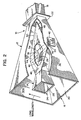
- the construction of the small radiator 14 is substantially the same as that of the large radiator 12, the small radiator 14 having a horn 24 and a throat 26 (Fig. 2) connected to the small end of the horn 24.
- the large end of the horn 24, opposite the throat 26, serves as a radiating aperture 28 of the small radiator 14.
- the throat 26 and the horn 24 are formed as a unitary structure by braising the throat 26 to the horn 24.
- the radiators 12 and 14 are formed of a metal, such as brass or aluminum.
- the horns 16 and 24 have rectangular cross section, as do the throats 18 and 26.
- the principles of the invention apply to horn radiators of other cross section, such as circular cross section.
- the horns 16 and 24 are disclosed as being tapered structures, it is noted that the principles of the invention also apply to a non-tapered horn such as an open-ended waveguide of constant cross section.
- the radiating apertures 20 and 28 are coplanar.
- the horn 24 of the small radiator 14 can be positioned such that its radiating aperture 28 is located forward of the radiating aperture 20 (outside the horn 16), or behind the radiating aperture 20 (inside the horn 16).
- the radiation patterns of the large radiator 12 are predicted by numerically integrating the modal fields existing over its aperture, and assuming the electric and magnetic fields to be of zero amplitude over the region of the horn 16 which is blocked by the horn 24. This enables optimization of the position of the horn 24 of the small radiator 14, and also enables accurate prediction of the gain, as well as the co-polar and cross-polar radiation patterns of the large radiator 12.
- the horn assembly 10 is advantageous to construct with symmetry in the mounting of the horn 24 within the horn 16. This is accomplished by bending the throat 26 of the small radiator 14 so that a distal end 30 thereof protrudes through a wall section 32 of the large horn 16 so as to provide physical contact with the wall section 32 for supporting the small radiator 14 within the horn 16. Protrusion of the distal end 30 of the throat 26 through the wall section 32 also provides a signal port for access to the small radiator 14 for applying electromagnetic signals to be radiated from the horn 24.
- a strut 34 which may be fabricated as a section of dummy waveguide is secured to the throat 26 at a bend 36 of the throat 26, and extends parallel to a distal leg 38 of the throat 26 and perpendicular to a proximal leg 40 of the throat 26. Center lines of the strut 34 and of the legs 38 and 40 are coplanar.
- the strut 34 and the distal leg 38 form a brace which extends transversely of both the horns 16 and 24, and contacts opposed wall sections 32 of the horn 16 to provide for a symmetrical mounting of the horn 24 within the horn 16,
- the strut 34 may be brazed to the bend 36 of the throat 26.
- a mounting flange 42 is brazed to the distal end 30 of the throat 26 to facilitate a connection of microwave circuitry to the small radiator 14 so as to provide a microwave signal to be transmitted by the small radiator 14, or for receiving incoming microwave signals incident upon the radiating aperture 28 of the small radiator 14.
- a flange (not shown) may be secured to a distal end of the throat 18 for connection of microwave circuitry to the large radiator 12.
- the strut 34 may be secured to a wall section 32A by passing an end of the strut 34 through an aperture 44 in the wall section 32A, and then brazing the end of the strut 34 to the wall section 32A.
- the distal leg 38 may be secured to the wall section 32 at an aperture 46 in the wall section 32.
- the horn 24 is positioned symmetrically within the horn 16, center lines of the two horns coinciding. During manufacture of the assembly 10, the wall sections 32 and 32A may be bowed outward slightly to clear ends of the strut 34 and the throat 26 to allow insertion within the horn 16 and emplacement in the apertures 44 and 46.
- the strut 34 and the throat 26 constitute a physical structure which can readily reflect waves of radiation propagating through the large radiator 12. Reflections of the radiation are undesirable because they decrease the effectiveness of transmission of microwave power through the large radiator 12 as is indicated by an increased value of standing wave ratio produced by such reflection.
- an electrically conductive sheet 48 is positioned within the large radiator 12 for enclosing the strut 34 and the throat 26 so as to guide the lower frequency radiation within the large radiator 12 past the region of a strut 34 and the throat 26 without reflection from these components.
- the sheet 48 may be constructed of copper foil or aluminum foil, the foil being sufficiently thick to provide for dimensional stability.
- the sheet 48 is folded so as to provide the configuration of a double taper.
- One taper directed towards the throat 18 produces a cone or pyramid 50 having an apex 52.
- the sheet 48 tapers in a tapered section 54 between forward edges of the strut 34 and the leg 38 to the four sides of the horn 24.
- the tapered. section 54 comprises four trapezoidal wall sections.
- the aforementioned brace is formed as a composite of the strut 34 and the leg 38 and is indicated at 56 (Fig. 1) as an outline in the sheet 48 of the structure of the brace.
- the sheet 48 lies flat on the top and the bottom surfaces of the brace 56, with reference to the orientation of the assembly 10 presented in Fig. 1. Both behind the brace 56, and in front of the brace 56, the sheet 48 undergoes the aforementioned tapering at the pyramid 50 and at the tapered section 54, respectively.
- the tapering of the sheet 48 provides for a gradual transition in the interior dimensions of the large radiator 12 so as to prevent the generation of excessive reflections.
- the sheet 48 accomplishes its function of allowing the large radiator 12 to function in a normal fashion, in spite of the presence of the small radiator 14.
- the horn assembly 10 can provide for the co-location of the high and the low frequency radiating apertures in a compact physical configuration while retaining the radiation characteristics of the individual radiator 12 and 14.
- the sides 58A and 58B of the radiating aperture 20 each measure 6.0 inches.
- the sides 60A and 60B of the radiating aperture 28 measure, respectively, 1.8 inches and 2.2 inches.
- the widths of the sides 62A and 62B measure, respectively, 1.145 inches and 2.29 inches.
- the sides 64A and 64B measure, respectively, 0.375 inches and 0.75 inches.
- the length of the horn 16, as measured along its center line from the radiating aperture 20 to the flange 22, is 10.0 inches.
- the length of the horn 24, as measured along its center line from the radiating aperture 28 to the junction with the throat 26, is 4.0 inches.
- the angles of taper in the construction of the sheet 48, as measured with respect to a center line of the horn assembly 10, are preferably in the range of 15 - 20 degrees, though other angles of taper may be employed, if desired, in accordance with accepted practice in the design of microwave transition structures.
- Fig. 3 shows an antenna system 66 which is useful in demonstrating use of the horn assembly 10.
- the antenna system 66 comprises a reflector 68, a plurality of radiators 70 arranged in an array which includes the horn assembly 10, a feed unit 72 such as a power splitter or Butler matrix, a C-band transceiver 74 coupled to the feed unit 72, and a Ku-band transceiver 76 connected by the flange 42 to the small radiator 14 of the horn assembly 10.
- the feed unit 72 applies C-band microwave power to each of the radiators 70 and also via the throat 18 to the large radiator 12 of the horn assembly 10.
- Each of the radiators 70 and the large radiator 12 of the horn assembly 10 direct microwave power to the reflector 68 for forming a C-band beam 78 which is transmitted to a distant site.
- the antenna system operates in reciprocal fashion so that an incoming beam 78 of radiation provides microwave signals which are received by the transceiver 74.
- the small radiator 14 of the horn assembly 10 directs microwave signals from the transceiver 76 towards the reflector 78 for forming a Ku band beam 80. Since the antenna system 66 operates in reciprocal fashion, an incoming band 80 of Ku-band microwave signals is directed by the small radiator 14 of the horn assembly 10 to the transceiver 76.
- the beams 78 and 80 are concentric by virtue of the use of a common reflector 68 for both the C-band and the Ku-band radiation, and due to the fact that a center one of the radiators of the system 66 employs the invention in the form of the horn assembly 10.
- the radiators 70 are depicted as being horn radiators having the same configuration as the large radiator 12 of the horn assembly 10. However, if desired, the horn assembly 10 of the invention can be employed with radiators of other physical configuration.
- Fig. 4 shows a further embodiment of the invention which functions in the same manner as that disclosed in Figs. 1 and 2, but is preferred because of its simpler construction.
- a horn assembly 82 comprises a large radiator 84 and a small radiator 86 nested within the large radiator 84 as was described in Figs. 1 and 2 with reference to the radiators 12 and 14, respectively.
- the large radiator 84 has the same configuration as the radiator 12.
- the small radiator 86 comprises the horn 24 and the throat 26 of the radiator 14 but differs in construction from the radiator 14 in that the horn 24 is joined to the throat 26 by a flange 88 rather than by the unitary construction of the radiator 14.
- the strut 34 and the distal leg 38 of the throat 26 are joined together to form the brace 56 which is oriented transversely of the common axis of the horns 16 and 24 for securing the small radiator 14 to the large radiator 12.
- the horn assembly 82 includes a sheet 90 which encloses the horn 24, the proximal leg 40 of the throat 26, the flange 88, and the central portion of the brace 56.
- the sheet 90 functions in the same fashion and serves the same purpose as the sheet 48 (Figs. 1 and 2).
- the sheet 90 has a simpler geometric form than the sheet 48, the sheet 90 being in the form of a simple pyramid which extends from a base at the radiating aperture 28 of the horn 14 to an apex at the flange 22 at the junction of the horn 16 with the throat 18 of the large radiator 12. Due to the simpler configuration of the sheet 90, the outer ends of the brace 56 extend through the sheet 90 to be exposed to the lower frequency radiation propagating within the large radiator 12.
- the resulting reflections of the electric field, E, of the lower frequency radiation may be regarded as being negligible because of the very small reflection of the electric field from the outer ends of the brace 56.
- the small amount of reflection is due to the presentation of the narrow wall of the distal leg to the radiation with the direction of the electric field, E, being perpendicular to the brace 56.
Landscapes
- Physics & Mathematics (AREA)
- Electromagnetism (AREA)
- Waveguide Aerials (AREA)
- Aerials With Secondary Devices (AREA)
- Variable-Direction Aerials And Aerial Arrays (AREA)
Applications Claiming Priority (2)
| Application Number | Priority Date | Filing Date | Title |
|---|---|---|---|
| US370659 | 1982-04-22 | ||
| US07/370,659 US4998113A (en) | 1989-06-23 | 1989-06-23 | Nested horn radiator assembly |
Publications (3)
| Publication Number | Publication Date |
|---|---|
| EP0403894A2 true EP0403894A2 (fr) | 1990-12-27 |
| EP0403894A3 EP0403894A3 (fr) | 1991-04-24 |
| EP0403894B1 EP0403894B1 (fr) | 1994-12-28 |
Family
ID=23460608
Family Applications (1)
| Application Number | Title | Priority Date | Filing Date |
|---|---|---|---|
| EP90110893A Expired - Lifetime EP0403894B1 (fr) | 1989-06-23 | 1990-06-08 | Dispositif imbriqué de radiateurs du type à cornet |
Country Status (5)
| Country | Link |
|---|---|
| US (1) | US4998113A (fr) |
| EP (1) | EP0403894B1 (fr) |
| JP (1) | JPH0671170B2 (fr) |
| CA (1) | CA2014661C (fr) |
| DE (1) | DE69015460T2 (fr) |
Cited By (2)
| Publication number | Priority date | Publication date | Assignee | Title |
|---|---|---|---|---|
| FR2808126A1 (fr) * | 2000-04-20 | 2001-10-26 | Cit Alcatel | Element rayonnant hyperfrequence bi-bande |
| CN102437430A (zh) * | 2011-09-21 | 2012-05-02 | 武汉滨湖电子有限责任公司 | 一种l、c双波段馈源 |
Families Citing this family (11)
| Publication number | Priority date | Publication date | Assignee | Title |
|---|---|---|---|---|
| JP3388694B2 (ja) * | 1997-09-01 | 2003-03-24 | シャープ株式会社 | 2周波共用一次放射器 |
| US6340953B1 (en) * | 1999-03-19 | 2002-01-22 | Matsushita Electric Industrial Co., Ltd. | Antenna device |
| JP3859520B2 (ja) * | 2002-01-28 | 2006-12-20 | Necエンジニアリング株式会社 | 導波管アンテナ |
| US6879298B1 (en) * | 2003-10-15 | 2005-04-12 | Harris Corporation | Multi-band horn antenna using corrugations having frequency selective surfaces |
| US7688269B1 (en) * | 2006-07-28 | 2010-03-30 | Rockwell Collins, Inc. | Stacked dual-band electromagnetic band gap waveguide aperture with independent feeds |
| DE102016014385A1 (de) * | 2016-12-02 | 2018-06-07 | Kathrein-Werke Kg | Dual polarisierter Hornstrahler |
| EP3790113B1 (fr) * | 2017-01-22 | 2023-03-08 | Huawei Technologies Co., Ltd. | Antenne double bande |
| CN107069225B (zh) * | 2017-04-27 | 2023-08-01 | 成都雷电微力科技股份有限公司 | 一种卡赛格伦天线馈源结构及卡赛格伦天线 |
| BR112020001288A2 (pt) * | 2018-07-26 | 2021-02-02 | Huawei Technologies Co., Ltd. | equipamento de alimentação, antena de micro-ondas de banda dupla e dispositivo de antena de banda dupla |
| US11658379B2 (en) * | 2019-10-18 | 2023-05-23 | Lockheed Martin Corpora Tion | Waveguide hybrid couplers |
| CN119231182B (zh) * | 2024-10-12 | 2025-09-05 | 西安伊鼎智能科技有限公司 | 一种小频比宽带双频双圆极化同轴共口径喇叭天线单元 |
Family Cites Families (7)
| Publication number | Priority date | Publication date | Assignee | Title |
|---|---|---|---|---|
| US2425488A (en) * | 1943-07-03 | 1947-08-12 | Rca Corp | Horn antenna |
| US2920322A (en) * | 1956-08-28 | 1960-01-05 | Jr Burton P Brown | Antenna system |
| US3566309A (en) * | 1969-02-24 | 1971-02-23 | Hughes Aircraft Co | Dual frequency band,polarization diverse tracking feed system for a horn antenna |
| FR2498820A1 (fr) * | 1981-01-23 | 1982-07-30 | Thomson Csf | Source hyperfrequence bi-bande et antenne comportant une telle source |
| US4740795A (en) * | 1986-05-28 | 1988-04-26 | Seavey Engineering Associates, Inc. | Dual frequency antenna feeding with coincident phase centers |
| DE3626856A1 (de) * | 1986-08-08 | 1988-02-11 | Licentia Gmbh | Antennenanordnung mit hornstrahlern |
| US4821046A (en) * | 1986-08-21 | 1989-04-11 | Wilkes Brian J | Dual band feed system |
-
1989
- 1989-06-23 US US07/370,659 patent/US4998113A/en not_active Expired - Fee Related
-
1990
- 1990-04-17 CA CA002014661A patent/CA2014661C/fr not_active Expired - Fee Related
- 1990-06-08 EP EP90110893A patent/EP0403894B1/fr not_active Expired - Lifetime
- 1990-06-08 DE DE69015460T patent/DE69015460T2/de not_active Expired - Fee Related
- 1990-06-22 JP JP2163019A patent/JPH0671170B2/ja not_active Expired - Lifetime
Cited By (4)
| Publication number | Priority date | Publication date | Assignee | Title |
|---|---|---|---|---|
| FR2808126A1 (fr) * | 2000-04-20 | 2001-10-26 | Cit Alcatel | Element rayonnant hyperfrequence bi-bande |
| EP1152483A1 (fr) * | 2000-04-20 | 2001-11-07 | Alcatel | Elément rayonnant hyperfréquence bi-bande |
| US6377224B2 (en) | 2000-04-20 | 2002-04-23 | Alcatel | Dual band microwave radiating element |
| CN102437430A (zh) * | 2011-09-21 | 2012-05-02 | 武汉滨湖电子有限责任公司 | 一种l、c双波段馈源 |
Also Published As
| Publication number | Publication date |
|---|---|
| US4998113A (en) | 1991-03-05 |
| EP0403894A3 (fr) | 1991-04-24 |
| DE69015460D1 (de) | 1995-02-09 |
| EP0403894B1 (fr) | 1994-12-28 |
| CA2014661A1 (fr) | 1990-12-23 |
| CA2014661C (fr) | 1994-09-20 |
| DE69015460T2 (de) | 1995-05-18 |
| JPH0335604A (ja) | 1991-02-15 |
| JPH0671170B2 (ja) | 1994-09-07 |
Similar Documents
| Publication | Publication Date | Title |
|---|---|---|
| US3568204A (en) | Multimode antenna feed system having a plurality of tracking elements mounted symmetrically about the inner walls and at the aperture end of a scalar horn | |
| US5959590A (en) | Low sidelobe reflector antenna system employing a corrugated subreflector | |
| US6137449A (en) | Reflector antenna with a self-supported feed | |
| US7167139B2 (en) | Hexagonal array structure of dielectric rod to shape flat-topped element pattern | |
| US4998113A (en) | Nested horn radiator assembly | |
| EP0155422A1 (fr) | Cornet à surface conique pour micro-ondes et transition de guide d'ondes | |
| US4972199A (en) | Low cross-polarization radiator of circularly polarized radiation | |
| US3500419A (en) | Dual frequency,dual polarized cassegrain antenna | |
| GB2233502A (en) | Slot array antenna | |
| US4380014A (en) | Feed horn for reflector antennae | |
| JPH03167906A (ja) | 誘電体集束ホーン | |
| CN111987464B (zh) | Ku/Ka波段双频锥形波束喇叭天线 | |
| US3883877A (en) | Optimized monopulse antenna feed | |
| US3380057A (en) | Dual band ridged feed horn | |
| US2473446A (en) | Antenna | |
| EP0268635B1 (fr) | Antenne a reflecteur avec organe d'alimentation auto-porteur | |
| US2591486A (en) | Electromagnetic horn antenna | |
| JPH01501035A (ja) | 直交モード電磁波発射装置 | |
| US4578681A (en) | Method and apparatus for optimizing feedhorn performance | |
| JP3364829B2 (ja) | アンテナ装置 | |
| US3212095A (en) | Low side lobe pillbox antenna employing open-ended baffles | |
| EP0155761A1 (fr) | Antenne à réflecteurs plan et parabolique avec cornet d'alimentation encastré | |
| GB2182806A (en) | Linearly polarized grid reflector antenna system with improved cross-polarization performance | |
| US3267477A (en) | Dual frequency microwave antenna | |
| US4689633A (en) | Flared microwave feed horns and waveguide transitions |
Legal Events
| Date | Code | Title | Description |
|---|---|---|---|
| PUAI | Public reference made under article 153(3) epc to a published international application that has entered the european phase |
Free format text: ORIGINAL CODE: 0009012 |
|
| 17P | Request for examination filed |
Effective date: 19900608 |
|
| AK | Designated contracting states |
Kind code of ref document: A2 Designated state(s): DE FR GB IT |
|
| PUAL | Search report despatched |
Free format text: ORIGINAL CODE: 0009013 |
|
| AK | Designated contracting states |
Kind code of ref document: A3 Designated state(s): DE FR GB IT |
|
| 17Q | First examination report despatched |
Effective date: 19930901 |
|
| GRAA | (expected) grant |
Free format text: ORIGINAL CODE: 0009210 |
|
| AK | Designated contracting states |
Kind code of ref document: B1 Designated state(s): DE FR GB IT |
|
| REF | Corresponds to: |
Ref document number: 69015460 Country of ref document: DE Date of ref document: 19950209 |
|
| ITF | It: translation for a ep patent filed | ||
| ET | Fr: translation filed | ||
| PLBE | No opposition filed within time limit |
Free format text: ORIGINAL CODE: 0009261 |
|
| STAA | Information on the status of an ep patent application or granted ep patent |
Free format text: STATUS: NO OPPOSITION FILED WITHIN TIME LIMIT |
|
| 26N | No opposition filed | ||
| PGFP | Annual fee paid to national office [announced via postgrant information from national office to epo] |
Ref country code: FR Payment date: 19980508 Year of fee payment: 9 |
|
| PGFP | Annual fee paid to national office [announced via postgrant information from national office to epo] |
Ref country code: GB Payment date: 19980522 Year of fee payment: 9 |
|
| PGFP | Annual fee paid to national office [announced via postgrant information from national office to epo] |
Ref country code: DE Payment date: 19980528 Year of fee payment: 9 |
|
| PG25 | Lapsed in a contracting state [announced via postgrant information from national office to epo] |
Ref country code: GB Free format text: LAPSE BECAUSE OF NON-PAYMENT OF DUE FEES Effective date: 19990608 |
|
| PG25 | Lapsed in a contracting state [announced via postgrant information from national office to epo] |
Ref country code: FR Free format text: THE PATENT HAS BEEN ANNULLED BY A DECISION OF A NATIONAL AUTHORITY Effective date: 19990630 |
|
| GBPC | Gb: european patent ceased through non-payment of renewal fee |
Effective date: 19990608 |
|
| PG25 | Lapsed in a contracting state [announced via postgrant information from national office to epo] |
Ref country code: DE Free format text: LAPSE BECAUSE OF NON-PAYMENT OF DUE FEES Effective date: 20000503 |
|
| REG | Reference to a national code |
Ref country code: FR Ref legal event code: ST |
|
| PG25 | Lapsed in a contracting state [announced via postgrant information from national office to epo] |
Ref country code: IT Free format text: LAPSE BECAUSE OF NON-PAYMENT OF DUE FEES;WARNING: LAPSES OF ITALIAN PATENTS WITH EFFECTIVE DATE BEFORE 2007 MAY HAVE OCCURRED AT ANY TIME BEFORE 2007. THE CORRECT EFFECTIVE DATE MAY BE DIFFERENT FROM THE ONE RECORDED. Effective date: 20050608 |