EP0404082A2 - Transducteur de pliage piézoélectrique et son utilisation - Google Patents
Transducteur de pliage piézoélectrique et son utilisation Download PDFInfo
- Publication number
- EP0404082A2 EP0404082A2 EP90111599A EP90111599A EP0404082A2 EP 0404082 A2 EP0404082 A2 EP 0404082A2 EP 90111599 A EP90111599 A EP 90111599A EP 90111599 A EP90111599 A EP 90111599A EP 0404082 A2 EP0404082 A2 EP 0404082A2
- Authority
- EP
- European Patent Office
- Prior art keywords
- bending transducer
- metallized
- transducer according
- valve
- layers
- Prior art date
- Legal status (The legal status is an assumption and is not a legal conclusion. Google has not performed a legal analysis and makes no representation as to the accuracy of the status listed.)
- Granted
Links
Images


Classifications
-
- H—ELECTRICITY
- H10—SEMICONDUCTOR DEVICES; ELECTRIC SOLID-STATE DEVICES NOT OTHERWISE PROVIDED FOR
- H10N—ELECTRIC SOLID-STATE DEVICES NOT OTHERWISE PROVIDED FOR
- H10N30/00—Piezoelectric or electrostrictive devices
- H10N30/20—Piezoelectric or electrostrictive devices with electrical input and mechanical output, e.g. functioning as actuators or vibrators
- H10N30/204—Piezoelectric or electrostrictive devices with electrical input and mechanical output, e.g. functioning as actuators or vibrators using bending displacement, e.g. unimorph, bimorph or multimorph cantilever or membrane benders
- H10N30/2041—Beam type
- H10N30/2042—Cantilevers, i.e. having one fixed end
-
- F—MECHANICAL ENGINEERING; LIGHTING; HEATING; WEAPONS; BLASTING
- F16—ENGINEERING ELEMENTS AND UNITS; GENERAL MEASURES FOR PRODUCING AND MAINTAINING EFFECTIVE FUNCTIONING OF MACHINES OR INSTALLATIONS; THERMAL INSULATION IN GENERAL
- F16K—VALVES; TAPS; COCKS; ACTUATING-FLOATS; DEVICES FOR VENTING OR AERATING
- F16K31/00—Actuating devices; Operating means; Releasing devices
- F16K31/004—Actuating devices; Operating means; Releasing devices actuated by piezoelectric means
- F16K31/005—Piezoelectric benders
- F16K31/006—Piezoelectric benders having a free end
-
- H—ELECTRICITY
- H10—SEMICONDUCTOR DEVICES; ELECTRIC SOLID-STATE DEVICES NOT OTHERWISE PROVIDED FOR
- H10N—ELECTRIC SOLID-STATE DEVICES NOT OTHERWISE PROVIDED FOR
- H10N30/00—Piezoelectric or electrostrictive devices
- H10N30/20—Piezoelectric or electrostrictive devices with electrical input and mechanical output, e.g. functioning as actuators or vibrators
- H10N30/204—Piezoelectric or electrostrictive devices with electrical input and mechanical output, e.g. functioning as actuators or vibrators using bending displacement, e.g. unimorph, bimorph or multimorph cantilever or membrane benders
- H10N30/2047—Membrane type
Definitions
- the invention relates to a piezoelectric bending transducer which contains at least one ceramic layer metallized on both sides with piezoelectric properties.
- a piezoelectrically actuable valve which contains in a housing an elongated piezo crystal arrangement clamped on one side, which can be connected to an electrical voltage source.
- the free (movable) end of the piezo crystal arrangement is provided with a sealing body. When sufficient voltage is applied, the piezo crystal moves sideways. The sealing body can thus close a valve channel.
- a disadvantage of this construction is that the application of sealing bodies to the piezo crystal requires an additional operation, and the mass of the bending transducer increases, i.e. its natural resonance is lowered. The bending transducer therefore loses speed. Fewer switching cycles per unit of time can therefore be driven. Since the sealing bodies also take up space, miniaturization of the valve is made more difficult.
- the invention is based on the knowledge that the piezoceramic layer itself is also suitable for sealing a valve channel if the roughness of the surface is less than 0.5 ⁇ m lies. With conventional metallization of the piezoceramic, which is necessary for the later generation of the field strength, however, higher roughness values are obtained.
- a piezoelectric bending transducer which is an essential component a) at least one metallized piezoelectric ceramic layer on both sides, which is polarized so that it undergoes a change in length when a voltage is applied and b) a flat shaped piece connected therewith with approximately the same area dimensions, which suffers no or an opposite linear expansion when a voltage is applied, contains.
- the bending transducer is characterized in that the ceramic layer has on at least one side a non-metallized point with a roughness R a of less than 0.5 ⁇ m. This non-metallized point should be in the zone of maximum deflection when the bending transducer is connected to a voltage source and clamped in a suitable manner.
- the non-metallized point should be slightly larger than the valve channel to be covered.
- the piezo layers are usually metallized by screen printing. In order to prevent the printing paste from flowing down the edge of the layer or to later jump over sparks at the edge, a narrow, approximately 0.3 mm wide strip is usually left unprinted on the edge. Such a strip is not sufficient to cover a valve channel.
- the non-metallized point should have the minimum dimensions of 1 x 1 mm.
- the non-metallized area should therefore be as closely connected as possible.
- the rigid flat shaped piece can be made of any material, e.g. be a metal sheet (no piezoelectric properties) or also a double-sided metallized ceramic layer with piezoelectric properties.
- a metal sheet no piezoelectric properties
- a double-sided metallized ceramic layer with piezoelectric properties.
- the metallized ceramic layer preferably has the shape of an elongated, usually rectangular strip.
- the non-metallized point is then at a narrow end of the strip.
- the strip is clamped on one side at the other end and supplied with voltage.
- Such a strip generally shows the length / width ratio from 1: 2 to 1: 4.
- the non-metallized area should be large enough to cover a rectangle whose length is at least equal to the width and whose width is at least 1 mm, more preferably at least 2 mm.
- the length / width ratio is preferably in the range from 1: 1 to 4: 1.
- a rectangular area of 2.3 x 7.4 mm or 2 x 10 mm or a circular area (diameter 1.5 - 2.5 mm) can be left without metallization on a strip of piezoceramic with an area of 25 x 10 mm.
- Circular areas are better for covering round valve openings. Rectangular areas can be manufactured more easily without metallization for manufacturing reasons.
- the ceramic layer with piezoelectric properties a circular shape and not to arrange the metallized point approximately in the center of the circle Such a bending transducer is clamped on the edge and the area that deflects the most when a voltage is applied is also in the center of the circle.
- a bending transducer which has the shape of an elongated strip
- piezoelectric ceramics e.g. based on lead zirconate titanate
- powders of metal oxides and metal carbonates are used as the starting materials in the majority of cases.
- the product with the final chemical composition is already obtained as a result of a solid-state reaction.
- Other methods such as Coprecipitation from dissolved raw materials are also used.
- the powder is usually subjected to a second grinding to reduce the grain diameter.
- liquid and plasticizer are added to the powder, creating a slip.
- the slurry is then dried by a spray process and pressed dry into the desired shape.
- Organic plasticizers and binders are added to the slip to produce thin parts. Thin, flexible films are obtained from the slip by film casting. The parts are punched out of these foils in the desired shape and sintered after the existing organic substances have been driven out. Then the parts are provided with metal electrodes.
- Piezoceramics with a small thickness can also be produced by pressing a piezomaterial in block form and sawing using suitable saws.
- the ceramic After the sinter firing, the ceramic is present as a polycrystalline body with randomly distributed electrical dipoles, i.e. it shows no piezoelectric activity yet. Only through the process of so-called polarization, i.e. Applying a high electric field, the dipoles are aligned almost completely.
- the orientation is largely retained even after the polarization field is switched off and is associated with a permanent change in the length of the body.
- ceramic layer thicknesses of less than 200 ⁇ m are selected. In this case, when applying a voltage of 24 volts and after clamping the transducer on the metallized Such a deflection at the non-metallized point takes place at the end of the strip such that a valve channel is securely closed.
- the stiffness of the bender is increased while the ceramic layer thicknesses remain the same, since the distance between the ceramic plates and the central neutral zone increases.
- both ceramic foils are generally polarized in the same direction in a bender consisting of only two ceramic layers.
- the bender is controlled so that one piezoceramic layer shortens (the field in the direction of polarization) while the other piezoceramic layer lengthens (the field opposite to the direction of polarization).
- the two outer electrodes of the upper and lower ceramic plate are electrically connected to one another in practical operation and form e.g. the negative connection, while the center electrode forms the positive pole.
- gluing metal sheet with metallized piezoceramic or two sintered, metallized ceramic foils to one another it is also possible to provide non-sintered piezoceramic raw foils with a suitable electrode material, laminate them together and then feed them to the sintering firing, whereby a monolithic piezoceramic bender is formed. Since the electrode material has to withstand sintering temperatures of 900 ° C to 1200 ° C without reacting with the metal oxides of the piezoceramic, only a few materials are suitable for this, e.g. Platinum.
- Gluing sintered, metallized piezoceramic plates with an organic adhesive e.g. a one-component methacrylate adhesive.
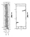
- FIG. 1a shows in cross section a piezoelectric bending transducer in strip form consisting of two ceramic layers (1, 2) metallized on both sides and a conductive intermediate layer, for example a metal sheet (3).
- the layers 1 and 2 are coated on both sides with the thin metallization layer (4).
- at one end of the strip there is a small area (5) on both sides free of metallization. This area serves as a sealing surface in contact with a valve channel (11).
- Bending transducers that have a non-metallized area on only one side can also be used (for certain valves).
- the polarization vector P has the same direction.
- the two layers (1) and (2) are glued to the intermediate layer (3).
- the thin layer of adhesive is not drawn. Power is supplied by wires (6), (7) and (8). At the end that has the power supply, the bending transducer is later mechanically clamped in the holder (9) and contacted at the same time. The length of the two piezo layers is not exactly the same, so that a power supply can be soldered onto the intermediate layer more easily. You could equally well make both ceramic layers of the same length and the metal sheet (3) a little longer.
- Figure (1b) shows the same bending transducer in supervision.
- Figure 2a shows in cross section a bending transducer in strip form, which consists of two piezoceramic layers (1, 2), each of which carries the metallization layer (4). A conductive intermediate layer is missing.
- the metallization layers (4) are connected to the power supply lines (6, 7) at one end. At the opposite end of the strip, a small area (5) of the layer without metallization remains on at least one side.
- the polarization vector P of the two layers (1, 2) is directed in the opposite direction.
- Figure 1b shows the same bending transducer in supervision.
- Figure (3a) shows in cross section an approximately circular bending element and a valve channel to be covered by the bending element. It contains an active piezoceramic layer (1), which has metallization zones (4) on both sides and is glued (adhesive not shown) with a circular metal sheet (3). The metal sheet (3) is mechanically clamped at its edge in a conductive circular holder (9). When the metallization zones (4) are electrically controlled by the current leads (6) and (7), the composite converter is deflected. The deflection is greatest in the center of the circular composite transducer. There is also the metallization-free zone (5), which lies against the opening (10) of the valve channel (11) and ensures its sealing.
- Figure 3b shows the same bending transducer (without clamping) in supervision.
Landscapes
- Engineering & Computer Science (AREA)
- General Engineering & Computer Science (AREA)
- Mechanical Engineering (AREA)
- Electrically Driven Valve-Operating Means (AREA)
- General Electrical Machinery Utilizing Piezoelectricity, Electrostriction Or Magnetostriction (AREA)
- Reciprocating Pumps (AREA)
- Electrophonic Musical Instruments (AREA)
- Piezo-Electric Or Mechanical Vibrators, Or Delay Or Filter Circuits (AREA)
- Piezo-Electric Transducers For Audible Bands (AREA)
Applications Claiming Priority (4)
| Application Number | Priority Date | Filing Date | Title |
|---|---|---|---|
| DE3920368 | 1989-06-22 | ||
| DE3920368 | 1989-06-22 | ||
| DE3935474 | 1989-10-25 | ||
| DE3935474A DE3935474A1 (de) | 1989-06-22 | 1989-10-25 | Piezoelektrischer biegewandler und seine verwendung |
Publications (3)
| Publication Number | Publication Date |
|---|---|
| EP0404082A2 true EP0404082A2 (fr) | 1990-12-27 |
| EP0404082A3 EP0404082A3 (fr) | 1991-07-03 |
| EP0404082B1 EP0404082B1 (fr) | 1996-01-24 |
Family
ID=25882197
Family Applications (1)
| Application Number | Title | Priority Date | Filing Date |
|---|---|---|---|
| EP90111599A Expired - Lifetime EP0404082B1 (fr) | 1989-06-22 | 1990-06-20 | Transducteur de pliage piézoélectrique et son utilisation |
Country Status (5)
| Country | Link |
|---|---|
| US (1) | US5079472A (fr) |
| EP (1) | EP0404082B1 (fr) |
| JP (1) | JP3133053B2 (fr) |
| AT (1) | ATE133481T1 (fr) |
| DE (2) | DE3935474A1 (fr) |
Cited By (12)
| Publication number | Priority date | Publication date | Assignee | Title |
|---|---|---|---|---|
| EP0544405A1 (fr) * | 1991-10-25 | 1993-06-02 | The Technology Partnership Limited | Vanne de régulation de débit à commande piézoélectrique |
| EP0615294A1 (fr) * | 1993-03-08 | 1994-09-14 | Ngk Insulators, Ltd. | Dispositif piézoélectrique |
| DE4410153C1 (de) * | 1994-03-24 | 1995-02-09 | Joucomatic Gmbh | Piezoelektrisch betätigtes Fluidventil |
| EP0656665A1 (fr) * | 1993-11-26 | 1995-06-07 | Ngk Insulators, Ltd. | Dispositif piézoélectrique |
| WO1996026377A1 (fr) * | 1995-02-21 | 1996-08-29 | Applied Power Inc. | Soupape a commande piezo-electrique |
| WO1997006008A1 (fr) * | 1995-08-05 | 1997-02-20 | Rea Elektronik Gmbh | Tete d'ecriture a jet d'encre |
| US5630440A (en) * | 1995-02-21 | 1997-05-20 | Applied Power Inc. | Piezo composite sheet actuated valve |
| WO1997046807A1 (fr) * | 1996-06-05 | 1997-12-11 | Tore Fors | Machine motrice |
| DE29722085U1 (de) * | 1997-12-13 | 1998-02-26 | Festo AG & Co, 73734 Esslingen | Ventil |
| DE19649225A1 (de) * | 1996-11-27 | 1998-05-28 | Nass Magnet Gmbh | Ventil |
| WO2009012833A1 (fr) | 2007-07-20 | 2009-01-29 | Hoerbiger Automatisierungstechnik Holding Gmbh | Soupape piézoélectrique |
| DE102013105557A1 (de) * | 2013-05-29 | 2014-12-04 | Michael Förg | Piezoelektrischer Aktor |
Families Citing this family (48)
| Publication number | Priority date | Publication date | Assignee | Title |
|---|---|---|---|---|
| JPH05217121A (ja) * | 1991-11-22 | 1993-08-27 | Internatl Business Mach Corp <Ibm> | 磁気変換器付きチップ等の感熱素子を結合する方法及び装置 |
| DE4411569C1 (de) * | 1994-04-02 | 1995-07-20 | Itw Dynatec Gmbh Klebetechnik | Auftragskopf zur dosierten Abgabe von strömenden Medien |
| US5628411A (en) * | 1994-12-01 | 1997-05-13 | Sortex Limited | Valve devices for use in sorting apparatus ejectors |
| US5780958A (en) * | 1995-11-03 | 1998-07-14 | Aura Systems, Inc. | Piezoelectric vibrating device |
| GB9610819D0 (en) * | 1996-05-22 | 1996-07-31 | Lucas Ind Plc | Valve arrangement |
| DE19627038C2 (de) * | 1996-07-05 | 1998-06-04 | Honeywell Bv | Piezoelektrischer Betätiger |
| US6086041A (en) * | 1997-04-07 | 2000-07-11 | Mccord Winn Textron Inc. | Multi-valve module having a ceramic piezoelectric actuator |
| DE19931990C1 (de) | 1999-07-09 | 2001-01-11 | Festo Ag & Co | Elektroventil |
| EP1106882A3 (fr) | 1999-12-09 | 2002-11-13 | Drei-S-Werk Präzisionswerkzeuge GmbH & Co. Fertigungs-KG | Soupape à commande piezo-électrique |
| DE19961736B4 (de) * | 1999-12-09 | 2006-08-31 | Caterpillar Inc., Peoria | Piezoelektrisch betätigbares Ventil |
| US6357335B1 (en) | 1999-12-23 | 2002-03-19 | Sox Corporation | Pneumatic volume booster for valve positioner |
| US6685164B1 (en) * | 2000-09-11 | 2004-02-03 | Hamai Industries Limited | Control valve and diaphragm for use in the control valve |
| JP2004532743A (ja) * | 2000-10-25 | 2004-10-28 | ワシントン ステート ユニバーシティ リサーチ ファウンデーション | 圧電マイクロトランスデューサ、その使用法および製造法 |
| DE10161888A1 (de) * | 2001-08-14 | 2003-02-27 | Continental Teves Ag & Co Ohg | Piezoelektrisch betätigtes Fluidventil |
| DE10233601A1 (de) | 2002-07-24 | 2004-02-19 | Fraunhofer-Gesellschaft zur Förderung der angewandten Forschung e.V. | Ventil mit kompaktem Betätigungsmechanismus |
| US20040144696A1 (en) | 2003-01-29 | 2004-07-29 | Stewart Mills | Valve device for use in sorting apparatus ejectors |
| KR100519970B1 (ko) * | 2003-10-07 | 2005-10-13 | 삼성전자주식회사 | 밸브리스 마이크로 공기공급장치 |
| DE102004033649A1 (de) * | 2004-07-12 | 2006-02-09 | Siemens Ag | Vorrichtung und Verfahren zum Einstellen einer Orientierung eines Detektorelements einer elektromagnetischen Strahlung und Kamera mit der Vorrichtung |
| US7078850B2 (en) * | 2004-07-20 | 2006-07-18 | Usc Corporation | Piezoelectric power generation device and piezoelectric ceramics member used therefor |
| US7594502B1 (en) | 2005-12-07 | 2009-09-29 | Anderson Joel A | Projectile loading, firing and warning system |
| DE102007034049B3 (de) | 2007-07-19 | 2008-06-12 | Hoerbiger Automatisierungstechnik Holding Gmbh | Piezoelektrisches Ventil |
| DE102007033529A1 (de) | 2007-07-19 | 2009-01-22 | Hoerbiger Automatisierungstechnik Holding Gmbh | Piezoelektrisches Ventil |
| JP2010251726A (ja) * | 2009-03-27 | 2010-11-04 | Ngk Insulators Ltd | 圧電アクチュエータの製造方法 |
| KR101443015B1 (ko) * | 2012-08-17 | 2014-09-22 | 엔지케이 인슐레이터 엘티디 | 복합 기판, 탄성 표면파 디바이스 및 복합 기판의 제조방법 |
| US10371136B2 (en) | 2016-01-29 | 2019-08-06 | Microjet Technology Co., Ltd. | Miniature pneumatic device |
| EP3203080B1 (fr) | 2016-01-29 | 2021-09-22 | Microjet Technology Co., Ltd | Dispositif pneumatique miniature |
| US10487820B2 (en) | 2016-01-29 | 2019-11-26 | Microjet Technology Co., Ltd. | Miniature pneumatic device |
| US10388849B2 (en) | 2016-01-29 | 2019-08-20 | Microjet Technology Co., Ltd. | Piezoelectric actuator |
| US10584695B2 (en) | 2016-01-29 | 2020-03-10 | Microjet Technology Co., Ltd. | Miniature fluid control device |
| US10385838B2 (en) | 2016-01-29 | 2019-08-20 | Microjet Technology Co., Ltd. | Miniature fluid control device |
| EP3203079B1 (fr) | 2016-01-29 | 2021-05-19 | Microjet Technology Co., Ltd | Actionneur piézoélectrique |
| US10451051B2 (en) | 2016-01-29 | 2019-10-22 | Microjet Technology Co., Ltd. | Miniature pneumatic device |
| US10529911B2 (en) | 2016-01-29 | 2020-01-07 | Microjet Technology Co., Ltd. | Piezoelectric actuator |
| EP3203077B1 (fr) | 2016-01-29 | 2021-06-16 | Microjet Technology Co., Ltd | Actionneur piézoélectrique |
| EP3203076B1 (fr) | 2016-01-29 | 2021-05-12 | Microjet Technology Co., Ltd | Dispositif miniature de régulation de fluides |
| JP6574452B2 (ja) * | 2016-01-29 | 2019-09-11 | 研能科技股▲ふん▼有限公司 | 小型空気圧動力装置 |
| US10655620B2 (en) | 2016-11-10 | 2020-05-19 | Microjet Technology Co., Ltd. | Miniature fluid control device |
| US10683861B2 (en) | 2016-11-10 | 2020-06-16 | Microjet Technology Co., Ltd. | Miniature pneumatic device |
| US10746169B2 (en) | 2016-11-10 | 2020-08-18 | Microjet Technology Co., Ltd. | Miniature pneumatic device |
| WO2018185821A1 (fr) * | 2017-04-03 | 2018-10-11 | オリンパス株式会社 | Unité piézoélectrique et outil de traitement |
| TWI686536B (zh) * | 2018-02-09 | 2020-03-01 | 研能科技股份有限公司 | 微型流體控制裝置 |
| US11186084B2 (en) | 2018-05-11 | 2021-11-30 | Matthews International Corporation | Electrode structures for micro-valves for use in jetting assemblies |
| US11639057B2 (en) | 2018-05-11 | 2023-05-02 | Matthews International Corporation | Methods of fabricating micro-valves and jetting assemblies including such micro-valves |
| US10994535B2 (en) | 2018-05-11 | 2021-05-04 | Matthews International Corporation | Systems and methods for controlling operation of micro-valves for use in jetting assemblies |
| US11794476B2 (en) | 2018-05-11 | 2023-10-24 | Matthews International Corporation | Micro-valves for use in jetting assemblies |
| AU2019265877B2 (en) | 2018-05-11 | 2024-10-03 | Matthews International Corporation | Systems and methods for sealing micro-valves for use in jetting assemblies |
| MX2022005266A (es) | 2019-11-01 | 2022-08-04 | Matthews Int Corp | Sistemas de deposicion sin contacto que incluyen ensambles de chorro. |
| CN114189787A (zh) * | 2021-11-23 | 2022-03-15 | 中国船舶重工集团公司第七一五研究所 | 一种压力补偿极低频弯曲圆盘换能器 |
Family Cites Families (18)
| Publication number | Priority date | Publication date | Assignee | Title |
|---|---|---|---|---|
| US3152612A (en) * | 1956-09-28 | 1964-10-13 | Gen Electric | Piezoelectric crystal transducer for controlling fluid flow |
| US3152012A (en) * | 1960-12-19 | 1964-10-06 | Ibm | Apparatus for the development of electrostatic images |
| JPS5492307A (en) * | 1977-12-29 | 1979-07-21 | Sony Corp | Driving circuit of electrostrictive converter |
| US4340083A (en) * | 1978-11-30 | 1982-07-20 | Carleton Controls Corporation | Deflectable beam valve |
| JPS6048112B2 (ja) * | 1979-05-02 | 1985-10-25 | ソニー株式会社 | 電気・機械変換素子 |
| DE3025596A1 (de) * | 1980-07-05 | 1982-02-25 | Feldmühle AG, 4000 Düsseldorf | Ventilscheibe aus oxidkeramischem werkstoff |
| US4492360A (en) * | 1982-06-07 | 1985-01-08 | The Lee Company | Piezoelectric valve |
| US4545561A (en) * | 1982-07-30 | 1985-10-08 | Mcdonnell Douglas Corporation | Piezoelectric valve operator |
| AT380934B (de) * | 1983-01-13 | 1986-07-25 | Enfo Grundlagen Forschungs Ag | Elektrisch-pneumatischer signalwandler |
| JPS59186380A (ja) * | 1983-04-06 | 1984-10-23 | Japan Storage Battery Co Ltd | バイモルフ型圧電体変位装置の制御方法 |
| JPS6062170A (ja) * | 1983-09-14 | 1985-04-10 | Teac Co | バイモルフ圧電駆動装置 |
| DE3425290A1 (de) * | 1984-07-10 | 1986-01-16 | Atlas Fahrzeugtechnik GmbH, 5980 Werdohl | Piezokeramische ventilplatte und verfahren zu deren herstellung |
| JPS6123373A (ja) * | 1984-07-11 | 1986-01-31 | Matsushita Electric Ind Co Ltd | 圧電変位素子 |
| AU5992286A (en) * | 1985-06-11 | 1987-01-07 | Arthur D. Little, Inc. | Apparatus for electrical control of rate of fluid flow |
| US4629926A (en) * | 1985-10-21 | 1986-12-16 | Kiwi Coders Corporation | Mounting for piezoelectric bender of fluid control device |
| DE3608550A1 (de) * | 1986-03-14 | 1987-09-17 | Festo Kg | Piezo-elektrisch betaetigbares ventil |
| DE3738630C2 (de) * | 1987-11-13 | 1995-06-08 | Rexroth Mannesmann Gmbh | Elektrohydraulische Druckwandlervorrichtung |
| JP6123569B2 (ja) | 2013-08-15 | 2017-05-10 | 株式会社ソシオネクスト | 電圧発生回路および電圧発生回路の制御方法 |
-
1989
- 1989-10-25 DE DE3935474A patent/DE3935474A1/de not_active Withdrawn
-
1990
- 1990-06-20 AT AT90111599T patent/ATE133481T1/de not_active IP Right Cessation
- 1990-06-20 DE DE59010081T patent/DE59010081D1/de not_active Expired - Fee Related
- 1990-06-20 EP EP90111599A patent/EP0404082B1/fr not_active Expired - Lifetime
- 1990-06-22 US US07/541,901 patent/US5079472A/en not_active Expired - Lifetime
- 1990-06-22 JP JP02165494A patent/JP3133053B2/ja not_active Expired - Fee Related
Cited By (17)
| Publication number | Priority date | Publication date | Assignee | Title |
|---|---|---|---|---|
| EP0544405A1 (fr) * | 1991-10-25 | 1993-06-02 | The Technology Partnership Limited | Vanne de régulation de débit à commande piézoélectrique |
| EP0615294A1 (fr) * | 1993-03-08 | 1994-09-14 | Ngk Insulators, Ltd. | Dispositif piézoélectrique |
| US5594292A (en) * | 1993-11-26 | 1997-01-14 | Ngk Insulators, Ltd. | Piezoelectric device |
| EP0656665A1 (fr) * | 1993-11-26 | 1995-06-07 | Ngk Insulators, Ltd. | Dispositif piézoélectrique |
| DE4410153C1 (de) * | 1994-03-24 | 1995-02-09 | Joucomatic Gmbh | Piezoelektrisch betätigtes Fluidventil |
| WO1995025920A1 (fr) * | 1994-03-24 | 1995-09-28 | Joucomatic Gmbh | Soupape pour fluides a commande piezo-electrique |
| US5630440A (en) * | 1995-02-21 | 1997-05-20 | Applied Power Inc. | Piezo composite sheet actuated valve |
| WO1996026377A1 (fr) * | 1995-02-21 | 1996-08-29 | Applied Power Inc. | Soupape a commande piezo-electrique |
| WO1997006008A1 (fr) * | 1995-08-05 | 1997-02-20 | Rea Elektronik Gmbh | Tete d'ecriture a jet d'encre |
| WO1997046807A1 (fr) * | 1996-06-05 | 1997-12-11 | Tore Fors | Machine motrice |
| DE19649225A1 (de) * | 1996-11-27 | 1998-05-28 | Nass Magnet Gmbh | Ventil |
| DE29722085U1 (de) * | 1997-12-13 | 1998-02-26 | Festo AG & Co, 73734 Esslingen | Ventil |
| WO2009012833A1 (fr) | 2007-07-20 | 2009-01-29 | Hoerbiger Automatisierungstechnik Holding Gmbh | Soupape piézoélectrique |
| US8220491B2 (en) | 2007-07-20 | 2012-07-17 | Hoerbiger Automatisierungstechnik Holding Gmbh | Piezoelectric valve |
| DE102013105557A1 (de) * | 2013-05-29 | 2014-12-04 | Michael Förg | Piezoelektrischer Aktor |
| DE102013105557B4 (de) * | 2013-05-29 | 2015-06-11 | Michael Förg | Piezoelektrischer Aktor |
| US9806250B2 (en) | 2013-05-29 | 2017-10-31 | Michael Förg | Piezoelectric actuator |
Also Published As
| Publication number | Publication date |
|---|---|
| JPH0365070A (ja) | 1991-03-20 |
| EP0404082B1 (fr) | 1996-01-24 |
| DE59010081D1 (de) | 1996-03-07 |
| ATE133481T1 (de) | 1996-02-15 |
| US5079472A (en) | 1992-01-07 |
| JP3133053B2 (ja) | 2001-02-05 |
| EP0404082A3 (fr) | 1991-07-03 |
| DE3935474A1 (de) | 1991-01-03 |
Similar Documents
| Publication | Publication Date | Title |
|---|---|---|
| EP0404082B1 (fr) | Transducteur de pliage piézoélectrique et son utilisation | |
| DE69311174T2 (de) | Piezoelektrisches/elektrostriktives Element mit Hilfselektrode zwischen einer piezoelektrischen/elektrostriktiven Schicht und dem Substrat | |
| DE69125762T2 (de) | Piezoelektrisches/elektrostriktives Antriebselement mit keramischem Substrat | |
| DE69505430T2 (de) | Piezoelektrisches/elektrostriktives Dünnfilmelement und Herstellungsverfahren | |
| DE69106431T2 (de) | Piezoelektrischer/elektrostriktiver Antrieb mit mindestens einer piezoelektrischen/elektrostriktiven Schicht. | |
| DE69629283T2 (de) | Ferroelektrischer dünnlagiger monomorpher verbundsensor und verfahren zu seiner herstellung | |
| EP1273051B1 (fr) | Transducteur a flexion piezoceramique et son utilisation | |
| EP0894341B1 (fr) | Element piezo-electrique monolithique d'actionnement a couches multiples et son procede de fabrication | |
| DE2828148C2 (de) | Biegeanordnung | |
| EP1908132B1 (fr) | Actionneur piezo-electrique monolithe a rotation du sens de polarisation dans la zone de transition et utilisation dudit actionneur piezo-electrique | |
| DE69014954T2 (de) | Geschichtete Keramikanordnung und Verfahren zu deren Herstellung. | |
| DE19757877A1 (de) | Verfahren zur Herstellung piezoelektrischer Aktoren und piezoelektrischer Aktor | |
| DE2258949A1 (de) | Elektretwandler und verfahren zu seiner herstellung | |
| DE4202650A1 (de) | Piezoelektrische zweielementkristall-einrichtung und verfahren zum treiben einer piezoelektrischen zweielementkristall-einrichtung | |
| DE2845022A1 (de) | Elektronisches schaltungsbauelement | |
| DE112018003429B4 (de) | Piezoelektrisches Bauteil, Sensor und Aktor | |
| DE4005184C2 (fr) | ||
| DE102011005990A1 (de) | Piezoelektrischer Stoffverbund, piezoelektrische Keramik, Wandler und Ultraschallmotor | |
| DE3736896A1 (de) | Elektroakustischer wandler | |
| US5841216A (en) | Composite piezoelectric multilayer element and method of manufacturing such an element | |
| DE102008002504A1 (de) | Verfahren zum Herstellen eines gestapelten Piezoaktors sowie Piezoaktor | |
| DE3138249A1 (de) | Kunstharz-impraegnierter piezokeramikkoerper | |
| DE102005033463B3 (de) | Piezoaktor | |
| DE2547606A1 (de) | Piezoelektrischer ultraschallumsetzer | |
| DE1226647B (de) | Elektroakustischer Wandler |
Legal Events
| Date | Code | Title | Description |
|---|---|---|---|
| PUAI | Public reference made under article 153(3) epc to a published international application that has entered the european phase |
Free format text: ORIGINAL CODE: 0009012 |
|
| AK | Designated contracting states |
Kind code of ref document: A2 Designated state(s): AT CH DE FR GB IT LI |
|
| 17P | Request for examination filed |
Effective date: 19901221 |
|
| PUAL | Search report despatched |
Free format text: ORIGINAL CODE: 0009013 |
|
| AK | Designated contracting states |
Kind code of ref document: A3 Designated state(s): AT CH DE FR GB IT LI |
|
| 17Q | First examination report despatched |
Effective date: 19930510 |
|
| GRAA | (expected) grant |
Free format text: ORIGINAL CODE: 0009210 |
|
| AK | Designated contracting states |
Kind code of ref document: B1 Designated state(s): AT CH DE FR GB IT LI |
|
| REF | Corresponds to: |
Ref document number: 133481 Country of ref document: AT Date of ref document: 19960215 Kind code of ref document: T |
|
| REF | Corresponds to: |
Ref document number: 59010081 Country of ref document: DE Date of ref document: 19960307 |
|
| ITF | It: translation for a ep patent filed | ||
| GBT | Gb: translation of ep patent filed (gb section 77(6)(a)/1977) |
Effective date: 19960402 |
|
| ET | Fr: translation filed | ||
| PLBE | No opposition filed within time limit |
Free format text: ORIGINAL CODE: 0009261 |
|
| STAA | Information on the status of an ep patent application or granted ep patent |
Free format text: STATUS: NO OPPOSITION FILED WITHIN TIME LIMIT |
|
| 26N | No opposition filed | ||
| REG | Reference to a national code |
Ref country code: CH Ref legal event code: PUE Owner name: HOECHST CERAMTEC AKTIENGESELLSCHAFT;HOERBIGER FLUI Ref country code: CH Ref legal event code: NV Representative=s name: PATENTANWAELTE SCHAAD, BALASS, MENZL & PARTNER AG |
|
| REG | Reference to a national code |
Ref country code: GB Ref legal event code: 732E |
|
| REG | Reference to a national code |
Ref country code: FR Ref legal event code: TP |
|
| REG | Reference to a national code |
Ref country code: GB Ref legal event code: IF02 |
|
| PGFP | Annual fee paid to national office [announced via postgrant information from national office to epo] |
Ref country code: DE Payment date: 20040527 Year of fee payment: 15 |
|
| PGFP | Annual fee paid to national office [announced via postgrant information from national office to epo] |
Ref country code: GB Payment date: 20040616 Year of fee payment: 15 Ref country code: FR Payment date: 20040616 Year of fee payment: 15 |
|
| PGFP | Annual fee paid to national office [announced via postgrant information from national office to epo] |
Ref country code: CH Payment date: 20040624 Year of fee payment: 15 Ref country code: AT Payment date: 20040624 Year of fee payment: 15 |
|
| PG25 | Lapsed in a contracting state [announced via postgrant information from national office to epo] |
Ref country code: IT Free format text: LAPSE BECAUSE OF NON-PAYMENT OF DUE FEES;WARNING: LAPSES OF ITALIAN PATENTS WITH EFFECTIVE DATE BEFORE 2007 MAY HAVE OCCURRED AT ANY TIME BEFORE 2007. THE CORRECT EFFECTIVE DATE MAY BE DIFFERENT FROM THE ONE RECORDED. Effective date: 20050620 Ref country code: GB Free format text: LAPSE BECAUSE OF NON-PAYMENT OF DUE FEES Effective date: 20050620 Ref country code: AT Free format text: LAPSE BECAUSE OF NON-PAYMENT OF DUE FEES Effective date: 20050620 |
|
| PG25 | Lapsed in a contracting state [announced via postgrant information from national office to epo] |
Ref country code: LI Free format text: LAPSE BECAUSE OF NON-PAYMENT OF DUE FEES Effective date: 20050630 Ref country code: CH Free format text: LAPSE BECAUSE OF NON-PAYMENT OF DUE FEES Effective date: 20050630 |
|
| PG25 | Lapsed in a contracting state [announced via postgrant information from national office to epo] |
Ref country code: DE Free format text: LAPSE BECAUSE OF NON-PAYMENT OF DUE FEES Effective date: 20060103 |
|
| REG | Reference to a national code |
Ref country code: CH Ref legal event code: PL |
|
| PG25 | Lapsed in a contracting state [announced via postgrant information from national office to epo] |
Ref country code: FR Free format text: LAPSE BECAUSE OF NON-PAYMENT OF DUE FEES Effective date: 20060228 |
|
| GBPC | Gb: european patent ceased through non-payment of renewal fee |
Effective date: 20050620 |
|
| REG | Reference to a national code |
Ref country code: FR Ref legal event code: ST Effective date: 20060228 |