EP0404165A2 - Appareil portable avec une partie divisée pour guider convenablement un câble qui connecte électriquement une unité de base à une unité d'affichage couplée de façon pivotable à l'unité de base - Google Patents
Appareil portable avec une partie divisée pour guider convenablement un câble qui connecte électriquement une unité de base à une unité d'affichage couplée de façon pivotable à l'unité de base Download PDFInfo
- Publication number
- EP0404165A2 EP0404165A2 EP90111797A EP90111797A EP0404165A2 EP 0404165 A2 EP0404165 A2 EP 0404165A2 EP 90111797 A EP90111797 A EP 90111797A EP 90111797 A EP90111797 A EP 90111797A EP 0404165 A2 EP0404165 A2 EP 0404165A2
- Authority
- EP
- European Patent Office
- Prior art keywords
- leg
- portable apparatus
- base unit
- cable
- base
- Prior art date
- Legal status (The legal status is an assumption and is not a legal conclusion. Google has not performed a legal analysis and makes no representation as to the accuracy of the status listed.)
- Granted
Links
Images


Classifications
-
- G—PHYSICS
- G06—COMPUTING OR CALCULATING; COUNTING
- G06F—ELECTRIC DIGITAL DATA PROCESSING
- G06F1/00—Details not covered by groups G06F3/00 - G06F13/00 and G06F21/00
-
- G—PHYSICS
- G06—COMPUTING OR CALCULATING; COUNTING
- G06F—ELECTRIC DIGITAL DATA PROCESSING
- G06F1/00—Details not covered by groups G06F3/00 - G06F13/00 and G06F21/00
- G06F1/16—Constructional details or arrangements
- G06F1/1613—Constructional details or arrangements for portable computers
- G06F1/1615—Constructional details or arrangements for portable computers with several enclosures having relative motions, each enclosure supporting at least one I/O or computing function
- G06F1/1616—Constructional details or arrangements for portable computers with several enclosures having relative motions, each enclosure supporting at least one I/O or computing function with folding flat displays, e.g. laptop computers or notebooks having a clamshell configuration, with body parts pivoting to an open position around an axis parallel to the plane they define in closed position
-
- G—PHYSICS
- G06—COMPUTING OR CALCULATING; COUNTING
- G06F—ELECTRIC DIGITAL DATA PROCESSING
- G06F1/00—Details not covered by groups G06F3/00 - G06F13/00 and G06F21/00
- G06F1/16—Constructional details or arrangements
- G06F1/1613—Constructional details or arrangements for portable computers
- G06F1/1633—Constructional details or arrangements of portable computers not specific to the type of enclosures covered by groups G06F1/1615 - G06F1/1626
- G06F1/1675—Miscellaneous details related to the relative movement between the different enclosures or enclosure parts
- G06F1/1681—Details related solely to hinges
-
- G—PHYSICS
- G06—COMPUTING OR CALCULATING; COUNTING
- G06F—ELECTRIC DIGITAL DATA PROCESSING
- G06F1/00—Details not covered by groups G06F3/00 - G06F13/00 and G06F21/00
- G06F1/16—Constructional details or arrangements
- G06F1/1613—Constructional details or arrangements for portable computers
- G06F1/1633—Constructional details or arrangements of portable computers not specific to the type of enclosures covered by groups G06F1/1615 - G06F1/1626
- G06F1/1675—Miscellaneous details related to the relative movement between the different enclosures or enclosure parts
- G06F1/1683—Miscellaneous details related to the relative movement between the different enclosures or enclosure parts for the transmission of signal or power between the different housings, e.g. details of wired or wireless communication, passage of cabling
Definitions
- the present invention relates to a portable apparatus such as a lap-top or portable computer and more particularly to a potable apparatus having a divided portion for suitably guiding a cable electrically connecting a base unit of the computer and a display unit connected to the base unit.
- U.S. Patent 4,571,456 discloses a portable computer which comprises a base unit, a keyboard attached to the base unit, and a display unit hinged to the base unit by a hinge mechanism.
- the hinge mechanism connects the display unit to the base unit such that the display unit can be rotated between a closed position where it coves the keyboard and an opened position where it is held up from the keyboard.
- the hinge mechanism comprises two trunnions horizontally protruding within the housing of the display unit, from the side walls of this housing, and two bearings mounted on the trunnions. The bearings are fitted in the grooves formed in the top surface of the base unit.
- the portable computer further comprises a flexible cable connecting the various components located within the base unit to the various components incorporated in the display unit.
- This cable extends through the hinge mechanism which connects the display unit to the base unit. More specifically, they extend from the base unit through the holes made in the bearings and having axes identical to those of the bearings, and further through the holes made in the housing of the display unit, into the display housing. Either bearing is mounted on the trunnion such that its hole is continuous to and coaxial with the hole of the display housing, so that it is easy to guide the cable out of the base unit into the housing of the display unit.
- both the base unit and display unit need to be thin, and the hinge mechanism for connecting the display unit to the base unit must also be thin.
- the components of the hinge mechanism such as bearings or trunnions, should be proportionally thin. The thinner the bearings, the smaller the diameter of their holes. The smaller the diameter of the holes, the more difficult it is to pass a cable through these holes, inevitably reducing the efficiency of assembling portable computers.
- An object of the present invention is to provide a portable apparatus, which facilitates the guidance of cable within the apparatus.
- a portable apparatus comprises: a display unit including a leg portion having a cable guide path; a base unit including a top cover having a leg mounting portion, for mounting the leg portion, having a opening; a cover, for covering the opening, having a cable guide portion; and a cable, guided through the cable guide path and the cable guide portion, including a first end having a first connector electrically connecting to the display unit and a second end having a second connector electrically connecting to the base unit.
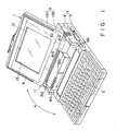
- Fig. 1 illustrates a lap-top computer 1.
- Computer 1 has a base unit 2 made of a synthetic resin and shaped like a thin rectangular box comprising a bottom case 3 which is covered by a top cover 4.
- a keyboard 5 is attached to the front portion of bottom case 3.
- the front portion of base unit 2 is thicker than the rear portion of base unit 2.
- Top cover 4 has a first recess 6a in front left portion of top cover 4 and a second recess 6b in front right portion of top cover 4, respectively.
- a printed circuit board 7, on which are mounted a number of circuit parts (not shown) is incorporated in base unit 2.
- computer 1 further comprises a flat-panel type display unit 8.
- Display unit 8 comprises a rectangular housing 9 and a flat liquid-crystal display 11 located within the housing 9.
- Housing 9 is composed of a base case 10a and a front case 10b, both shaped like a rectangular plate. These cases 10a and 10b are fastened together, by screws (not shown) at their four corners.
- display unit 8 is pivotaly coupled to main body 2.
- Display unit 8 rotates between a closed position where display unit 8 covers keyboard 5 and an open position for exposing keyboard 5 and screen 12 to operating computer 1, as arrow A.
- display unit 8 remains in the closed position, its top is at the same level as the upper surface of top cover 4, and its left and right sides are level with those of top cover 4. In this condition, main body 2 and display unit 8 form a relatively thin box, which is quite portable.
- Display unit 8 has a first leg portion 15a and a second leg portion 15b.
- First leg portion 15a protrudes from a lower-left portion of the housing 9.
- Second leg portion 15b protrudes from a lower right portion of the housing 9.
- First leg portion 15a is mounted in first recess 6a and second leg portion 15b is mounted in second recess 6b, respectively.
- first leg portion 15a has a rear leg segment 16 protruding from and conjoining base case 10a and a front leg segment 17 removably fastened to the front of rear leg segment 16.
- front leg segment 17 has a claw 18 projecting from the side which connects to rear leg segment 16.
- claw 18 engages a lock hole 19 formed in the inner side of rear leg segment 16, whereby segments 16 and 17 are fastened together, forming first leg portion 15a.
- Leg segments 16 and 17, thus fastened together, define a guide path 20.
- the front leg segment 17 also has a guide portion 21 for guiding a cable 53 into the housing 9.
- Guide portion 21 has a communication port 22 at its tip.
- Port 22 opens to the interior of housing 9, thus allowing guide path 20 to communicate with the interior of housing 9.
- Segment 17 further has a fixing tongue piece 24 which is attached to guide portion 21 and aligns with a boss 23 protruding from base case 10a, and has a positioning hole 25.
- a positioning projection 26, protruding from base case 10a is inserted in hole 25, thereby aligning front leg segment 17 with rear leg segment 16.
- leg segments 16 and 17 are firmly connected by a screw 27 set in screw engagement with bosses 23, thus forming leg portion 15a.
- a stepped portion of front leg segment 17, which is continuous to guide portion 21, has a hole 28 opening into the interior of leg segment 17.
- leg segments 16 and 17 have, respectively, half-cylinders 31a and 31b, which are situated on the outer sides and connect to each other.
- Half-cylinders 31a and 31b define U-shaped notches 30a and 30b.
- These half-cylinders 31a and 31b form a hollow shaft 32 having a guide path 33.
- Guide path 33 communicates with guide path 20 defined by the leg segments 16 and 17.
- half-cylinder 31a of rear leg segment 16 has two arcuate projections 34a and 34b opposing each other and extending into front leg segment 17.
- the distance L1 between the tips of arcuate projections 34a and 34b is shorter than the inside diameter L2 of hollow shaft 32.
- First leg portion 15a extends into recess 6a of the base unit 2.
- the recess 6a has an opening 38.
- Opening 38 has two sections 39 and 40.
- Section 39 is cut in the outermost of the two opposing side walls which define the inner and outer faces of the recess 6a.
- Section 40 is made in the face which defines the bottom of the recess 6a.
- a receiving section 41 which is upper edge of section 39 is arcuate, so that shaft 32 is rotatably fitted in opening 38.
- a support segment 43 which is made of a synthetic resin, is located in opening 38, extending from below top cover 4. Support segment 43 is fastened to a wall defining a bottom of recess 6a. Support segment 43 has a side wall 44 and a bottom wall 45 which are fitted in sections 39 and 40 of opening 38, respectively, and two flanges 46, connected to the front and rear edges of side wall 39, which are fastened to bosses 47 protruding downward from the inner surface of top cover 4, by screws 48.
- An arcuate notch 50 into which shaft 32 is rotatably fitted, is cut in the upper edge of side wall 44 so as to oppose receiving section 41 in main body 2. Notch 50 and the section 41 form a circular hole 51, through which the shaft 32 rotatably extends.
- a guide wall 52 which is taller than side wall 44 and also has an arcuate notch 50, is formed integral with wall 44.
- Hole 51 communicates with guide path 20 formed in first leg portion 15a through guide path 33 formed in shaft 32. Hence, guide paths 20 and 33 and hole 51 connect the interior of main body 2 to that of the housing 9. Cable 53 extends through paths 20 and 33 and hole 51, thus electrically connecting printed circuit board 7 to liquid-crystal display 11.
- cable 53 is flexible, and has connectors 54a and 54b attached to its ends.
- Connectors 54a and 54b are elongated members larger than hole 51.
- Connector 54a extends into base unit 2 and connected to printed circuit board 7.
- Connector 54b extends into housing 9 and connected to liquid-crystal display 11.
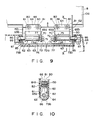
- second leg portion 15b has a rear leg segment 60 conjoining base case 10a and a front leg segment 61 conjoining front case 10b. Second leg portion 15b extends horizontally longer than first leg portion 15a. Second leg portion 15b contains a pair of hinge brake mechanisms 62, which support housing 9 in an arbitrary position between the closed position and the open position.
- a first and a second hinge brake mechanisms 62 are located in a inner and an outer ends of second leg portion 15b, respectively.
- Hinge brake mechanisms 62 are designed not only to support housing 9, but also to hold housing 9 at any position between the closed position and the open position.
- Hinge brake mechanisms 62 are identical in structure, and only one of them will, therefore, be described in detail with reference to Figs. 11 and 12.
- each hinge brake mechanism 62 has a straight shaft 63 and a bracket 64 made of metal and supporting shaft 63.
- Bracket 64 comprises a pair of support pieces 65a and 65b spaced apart in the axial direction of shaft 63, and a fixing section 66 connecting these pieces 65a and 65b.
- Support pieces 65a and 65b each have a hole 67, and are so positioned that the holes 67 are coaxial.
- An ends of shaft 63 are rotatably supported in these holes 67.
- a left end of shaft 63 has a screw hole.
- a screw 72 is inserted in this screw hole, with a plain washer 70 and a spring washer 71 interposed between screw 72 and left end of shaft 63.
- Plain washer 70, spring washer 71, and head 72a of screw 72 have diameters larger than those of holes 67.
- plain washer 70 abuts on the outer side of support piece 65a, whereby washers 70, 71 and screw 72 prevent shaft 63 from slipping from hinge brake mechanism 62.
- Shaft 63 has a thick portion 73a and two thin portions 73b extending from the ends of portion 73a.
- a first thin portion 73b is inserted in hole 67 of support pieces 65b.
- a second thin portion 73b is inserted in hole 67 of support piece 65a.
- a plain washer 75 having an outside diameter larger than the diameter of thick portion 73a is mounted on thin portion 73b and abuts a right end 74 of thick portion 73a.
- Two wave washers 77 having an outside diameter substantially the same as the diameter of thick portion 73a are mounted on thin portion 73b. Washers 77 compressed between plain washer 75 and support piece 65a of bracket 64.
- Two wave washers 77 which function as springs, abut plain washer 75 and support piece 65a, respectively. A friction force is thereby generated between plain washer 75 and bracket 64, restricting the rotation of shaft 64 which is supported by bracket 64.
- two wave washers 77 are used to restrict the rotation of shaft 64.
- one wave washer, or three or more wave washers may be used for the same purpose in the present invention.
- first and second hinge brake mechanisms 62 are fastened to first and second bosses 80, respectively, by screws 81. Both hinge brake mechanisms 62 are connected to housing 9. As is shown in Fig. 10, one of screws 81 which fasten either fixing section 66 to bosses 80 passes through the hole cut in front leg segment 61. Screws 81 fastens front leg segment 61 to rear leg segment 60. A cover 82 is removably connected to front leg segment 61, thus concealing heads 81a of screws 81.
- one of thin portions 73b of either shaft 63 extends into base unit 2 through hole 85 made in the side wall of base unit 2.
- An end 86 of portion 73b which is located within base unit 2 has a polygonal cross section.
- An end 86 of thin portion 73b is fitted in a corresponding hole 88 made in a support 87 which protrudes downward from the top wall of base unit 2.
- Display unit 8 has leg section 15a connected to the base unit 2 by shaft 32 held in hole 51 as is shown in Figs. 2 and 3, and has leg section 15b connected to base unit 2 by hinge brake mechanisms 62 as is shown in Fig. 9. Display unit 8 is thus rotatably supported on base unit 2.
- front case 10b and front leg segment 17 are removed from base case 10a of housing 9. Also, top cover 4 is detached from bottom case 3 and support segment 43 is removed from top cover 4.
- opening 38 is formed in the outermost of two opposing side walls which define the outer and inner faces of first recess 6a, and the wall which define the bottom of first recess 6a. Opening 38 is larger than connector 54a attached to printed circuit board 7. The end portion of cable 53 to which the connector 54a is connected is inserted into base unit 2 through opening 38.
- support segment 43 is fitted into opening 38 from within top cover 4, with cable 53 resting in U-notch 50.
- Flanges 46 of support segment 43 are then fastened to bosses 47 by screws 48.
- support segment 43 is secured to housing 9, whereby U-notch 50 of support segment 43 and receiving section 41 of top cover 4 define hole 51. Cable 53 passes through hole 51.
- front leg segment 17 does not conjoin front case 10b. But even though front leg segment 17 conjoins front case 10b, same object and advantage will be achieved.
Landscapes
- Engineering & Computer Science (AREA)
- Theoretical Computer Science (AREA)
- Computer Hardware Design (AREA)
- Physics & Mathematics (AREA)
- General Physics & Mathematics (AREA)
- General Engineering & Computer Science (AREA)
- Human Computer Interaction (AREA)
- Computer Networks & Wireless Communication (AREA)
- Mathematical Physics (AREA)
- Casings For Electric Apparatus (AREA)
- Insertion, Bundling And Securing Of Wires For Electric Apparatuses (AREA)
- Pivots And Pivotal Connections (AREA)
- Devices For Indicating Variable Information By Combining Individual Elements (AREA)
Applications Claiming Priority (2)
| Application Number | Priority Date | Filing Date | Title |
|---|---|---|---|
| JP162224/89 | 1989-06-23 | ||
| JP1162224A JP2786677B2 (ja) | 1989-06-23 | 1989-06-23 | 小型電子機器 |
Publications (3)
| Publication Number | Publication Date |
|---|---|
| EP0404165A2 true EP0404165A2 (fr) | 1990-12-27 |
| EP0404165A3 EP0404165A3 (fr) | 1992-08-05 |
| EP0404165B1 EP0404165B1 (fr) | 1996-08-14 |
Family
ID=15750331
Family Applications (1)
| Application Number | Title | Priority Date | Filing Date |
|---|---|---|---|
| EP90111797A Expired - Lifetime EP0404165B1 (fr) | 1989-06-23 | 1990-06-21 | Appareil portable avec une partie divisée pour guider convenablement un câble qui connecte électriquement une unité de base à une unité d'affichage couplée de façon pivotable à l'unité de base |
Country Status (5)
| Country | Link |
|---|---|
| US (3) | US5090913A (fr) |
| EP (1) | EP0404165B1 (fr) |
| JP (1) | JP2786677B2 (fr) |
| KR (1) | KR930005795B1 (fr) |
| DE (1) | DE69028047T2 (fr) |
Families Citing this family (36)
| Publication number | Priority date | Publication date | Assignee | Title |
|---|---|---|---|---|
| US5240427A (en) * | 1989-06-23 | 1993-08-31 | Kabushiki Kaisha Toshiba | Portable apparatus having cable electrically connecting display unit and base unit |
| US5238421A (en) * | 1989-06-23 | 1993-08-24 | Kabushiki Kaisha Toshiba | Portable apparatus having cable electrically connecting display unit and base unit |
| JP2786677B2 (ja) * | 1989-06-23 | 1998-08-13 | 株式会社東芝 | 小型電子機器 |
| JPH05189084A (ja) * | 1992-01-10 | 1993-07-30 | Toshiba Corp | 小形電子機器 |
| USD358583S (en) | 1993-04-29 | 1995-05-23 | Medtronic, Inc. | Portable computer with an articulating display panel |
| US5345362A (en) * | 1993-04-29 | 1994-09-06 | Medtronic, Inc. | Portable computer apparatus with articulating display panel |
| US5552967A (en) * | 1993-04-30 | 1996-09-03 | Kabushiki Kaisha Toshiba | Portable electronic apparatus having a housing for containing circuits board and functional components |
| US5419626A (en) * | 1993-09-01 | 1995-05-30 | Ncr Corporation | Computer housing seal |
| US5796579A (en) * | 1994-05-31 | 1998-08-18 | Kabushiki Kaisha Toshiba | Portable electronic apparatus having expansion connector covered by pivotally mounted upper and lower covers having laterally extending guide portions |
| US5689400A (en) * | 1994-05-31 | 1997-11-18 | Kabushiki Kaisha Toshiba | Portable electronic apparatus including space-saving component mounting features |
| US5745340A (en) * | 1994-12-19 | 1998-04-28 | Landau; Jennifer | Separable display of computer generated information |
| JP2658935B2 (ja) * | 1994-12-30 | 1997-09-30 | 日本電気株式会社 | ヒンジ構造を有する電子装置 |
| FI100038B (fi) * | 1995-12-22 | 1997-08-29 | Nokia Mobile Phones Ltd | Saranoitu laite |
| JP3519554B2 (ja) * | 1996-09-20 | 2004-04-19 | 株式会社東芝 | 携帯型電子機器 |
| US6838810B1 (en) * | 1997-03-21 | 2005-01-04 | Chunghwa Picture Tubes, Ltd. | Flat-panel display mounting system for portable computer |
| JPH10268976A (ja) * | 1997-03-27 | 1998-10-09 | Toshiba Corp | 携帯形電子機器 |
| US6002457A (en) * | 1997-04-08 | 1999-12-14 | Lg Lcd, Inc. | Computer having liquid crystal display |
| JP3296993B2 (ja) * | 1997-04-08 | 2002-07-02 | エルジー フィリップス エルシーディー カンパニー リミテッド | 液晶表示装置を備える携帯用コンピュータ |
| KR100218581B1 (ko) | 1997-04-08 | 1999-09-01 | 구자홍 | 액정표시장치를 가지는 휴대용 컴퓨터 |
| KR100256971B1 (ko) | 1997-05-24 | 2000-05-15 | 구본준 | 노트북 퍼스날컴퓨터의 액정표시모듈 고정방법 및 장치 |
| US7492421B1 (en) | 1997-07-03 | 2009-02-17 | Lg Display Co., Ltd. | Case for liquid crystal display |
| FI980603A7 (fi) * | 1998-03-18 | 1999-09-19 | Nokia Corp | Saranoitu elektroninen laite |
| US6501641B1 (en) * | 1998-10-23 | 2002-12-31 | Lg. Philips Lcd Co. Ltd. | Portable computer having a flat panel display device |
| KR100508003B1 (ko) * | 1998-11-11 | 2005-11-21 | 엘지.필립스 엘시디 주식회사 | 휴대용컴퓨터와그평판표시장치의결합방법 |
| NZ507104A (en) * | 2000-09-22 | 2001-11-30 | New Zealand Dairy Board | Dairy product and process for making cheese containing gum |
| JP2002288978A (ja) * | 2001-03-22 | 2002-10-04 | Sony Corp | 電子機器 |
| US6555745B1 (en) | 2001-10-19 | 2003-04-29 | Medtronic, Inc. | Electrical interconnect between an articulating display and a PC based planar board |
| CN1279418C (zh) * | 2001-12-24 | 2006-10-11 | Lg电子株式会社 | 用于平板显示器设备的铰接组件 |
| US6657856B1 (en) * | 2002-07-08 | 2003-12-02 | Lu Sheng-Nan | Hinge for a notebook computer |
| CN1510883A (zh) * | 2002-12-24 | 2004-07-07 | 北京嘉盛联侨信息工程技术有限公司 | 一种旋翼式手机及其控制方法 |
| CN1510884A (zh) * | 2002-12-24 | 2004-07-07 | ������ʢ������Ϣ���̼�������˾ | 旋翼式数字移动通讯设备的旋转轴及其安装方式 |
| DE102007026498A1 (de) * | 2007-06-05 | 2008-12-11 | Endress + Hauser Wetzer Gmbh + Co Kg | Vorrichtung zur Bestimmung und/oder Überwachung einer Prozessgröße |
| JP4978567B2 (ja) * | 2008-06-10 | 2012-07-18 | 富士通株式会社 | 電子機器 |
| JP2011141704A (ja) * | 2010-01-06 | 2011-07-21 | Funai Electric Co Ltd | 電子機器装置 |
| JP2011170809A (ja) * | 2010-02-22 | 2011-09-01 | Funai Electric Co Ltd | 電子機器装置 |
| US9405331B2 (en) | 2014-08-07 | 2016-08-02 | Dell Products L.P. | Cable grounding system for an information handling system |
Family Cites Families (10)
| Publication number | Priority date | Publication date | Assignee | Title |
|---|---|---|---|---|
| US4571456B1 (en) * | 1982-10-18 | 1995-08-15 | Grid Systems Corp | Portable computer |
| JPS60225920A (ja) * | 1984-04-25 | 1985-11-11 | Seiko Epson Corp | 情報機器 |
| US4730364A (en) * | 1985-10-29 | 1988-03-15 | Bondwell Holding Ltd. | Data processor flush hinge assembly |
| US4781422A (en) * | 1985-11-14 | 1988-11-01 | Random Corporation | Adjustable clutch mechanism |
| JPS6343223U (fr) * | 1986-09-04 | 1988-03-23 | ||
| JP2880729B2 (ja) * | 1989-06-23 | 1999-04-12 | 株式会社東芝 | 小型電子機器 |
| US5238421A (en) * | 1989-06-23 | 1993-08-24 | Kabushiki Kaisha Toshiba | Portable apparatus having cable electrically connecting display unit and base unit |
| JP2786677B2 (ja) * | 1989-06-23 | 1998-08-13 | 株式会社東芝 | 小型電子機器 |
| US5041818A (en) * | 1990-05-21 | 1991-08-20 | Lapro Corporation | Lid with movement control device |
| JP2986180B2 (ja) * | 1990-06-25 | 1999-12-06 | 株式会社東芝 | 携帯形機器 |
-
1989
- 1989-06-23 JP JP1162224A patent/JP2786677B2/ja not_active Expired - Fee Related
-
1990
- 1990-06-21 EP EP90111797A patent/EP0404165B1/fr not_active Expired - Lifetime
- 1990-06-21 DE DE69028047T patent/DE69028047T2/de not_active Expired - Fee Related
- 1990-06-22 KR KR1019900009231A patent/KR930005795B1/ko not_active Expired - Fee Related
- 1990-06-22 US US07/542,061 patent/US5090913A/en not_active Expired - Lifetime
-
1993
- 1993-05-19 US US08/063,332 patent/US5328379A/en not_active Expired - Lifetime
-
1994
- 1994-04-13 US US08/226,894 patent/US5433620A/en not_active Expired - Lifetime
Non-Patent Citations (1)
| Title |
|---|
| None |
Also Published As
| Publication number | Publication date |
|---|---|
| DE69028047T2 (de) | 1997-01-16 |
| US5433620A (en) | 1995-07-18 |
| EP0404165A3 (fr) | 1992-08-05 |
| JPH0327412A (ja) | 1991-02-05 |
| JP2786677B2 (ja) | 1998-08-13 |
| KR930005795B1 (ko) | 1993-06-25 |
| KR920001292A (ko) | 1992-01-30 |
| US5090913A (en) | 1992-02-25 |
| EP0404165B1 (fr) | 1996-08-14 |
| US5328379A (en) | 1994-07-12 |
| DE69028047D1 (de) | 1996-09-19 |
Similar Documents
| Publication | Publication Date | Title |
|---|---|---|
| EP0404165A2 (fr) | Appareil portable avec une partie divisée pour guider convenablement un câble qui connecte électriquement une unité de base à une unité d'affichage couplée de façon pivotable à l'unité de base | |
| EP0404166A2 (fr) | Articulation avec un mécanisme pour arrêter le membre mobile dans la position ouverte | |
| US5238421A (en) | Portable apparatus having cable electrically connecting display unit and base unit | |
| US7221562B2 (en) | Portable computer | |
| EP1628191B1 (fr) | Ordinateur portable. | |
| JP2986180B2 (ja) | 携帯形機器 | |
| US6272006B1 (en) | Hinge device for a portable computer | |
| EP1696303B1 (fr) | Dispositif de traitement de données | |
| EP1681613A2 (fr) | Appareil d'ajustage automatique de l'angle du dispositif d'image de l'équipement de traitement de l'information | |
| CA2045299C (fr) | Appareil electronique portable a batterie amovible et a composant faculfatif pour elargissement d'une fonction | |
| EP0446414A2 (fr) | Ordinateur avec unité d'affichage pouvant être pivotée et clavier amovible | |
| EP0425792A2 (fr) | Appareil électronique portable avec charnière protÀ©geant électriquement | |
| KR20050012927A (ko) | 휴대용 컴퓨터 | |
| KR20020057436A (ko) | 휴대용컴퓨터 | |
| US5240427A (en) | Portable apparatus having cable electrically connecting display unit and base unit | |
| KR101236391B1 (ko) | 정보처리장치 | |
| US7365994B2 (en) | Bracket for expansion card slot | |
| JP3287106B2 (ja) | 机上配線装置 | |
| KR20010041980A (ko) | 탈착 가능하게 고정된 키보드를 구비한 노트북 컴퓨터 | |
| KR100265707B1 (ko) | 전자 시스템의 브래킷 장착 구조 및 전자 시스템의 브래킷 장착구조가 사용된 휴대용 컴퓨터 | |
| KR100690908B1 (ko) | 정보처리기기의 영상 유닛 각도 자동조절장치 | |
| JP4060418B2 (ja) | 開閉可能なディスプレイユニットを有する携帯形情報機器 | |
| KR20040005519A (ko) | 일체형 컴퓨터 | |
| KR0114102Y1 (ko) | 모니터의 회로기판 고정장치 | |
| KR20000037753A (ko) | 휴대용 정보기기의 힌지장치 |
Legal Events
| Date | Code | Title | Description |
|---|---|---|---|
| PUAI | Public reference made under article 153(3) epc to a published international application that has entered the european phase |
Free format text: ORIGINAL CODE: 0009012 |
|
| 17P | Request for examination filed |
Effective date: 19900718 |
|
| AK | Designated contracting states |
Kind code of ref document: A2 Designated state(s): DE FR GB IT |
|
| PUAL | Search report despatched |
Free format text: ORIGINAL CODE: 0009013 |
|
| AK | Designated contracting states |
Kind code of ref document: A3 Designated state(s): DE FR GB IT |
|
| 17Q | First examination report despatched |
Effective date: 19950203 |
|
| GRAH | Despatch of communication of intention to grant a patent |
Free format text: ORIGINAL CODE: EPIDOS IGRA |
|
| GRAH | Despatch of communication of intention to grant a patent |
Free format text: ORIGINAL CODE: EPIDOS IGRA |
|
| GRAA | (expected) grant |
Free format text: ORIGINAL CODE: 0009210 |
|
| AK | Designated contracting states |
Kind code of ref document: B1 Designated state(s): DE FR GB IT |
|
| ITF | It: translation for a ep patent filed | ||
| REF | Corresponds to: |
Ref document number: 69028047 Country of ref document: DE Date of ref document: 19960919 |
|
| ET | Fr: translation filed | ||
| PLBE | No opposition filed within time limit |
Free format text: ORIGINAL CODE: 0009261 |
|
| STAA | Information on the status of an ep patent application or granted ep patent |
Free format text: STATUS: NO OPPOSITION FILED WITHIN TIME LIMIT |
|
| 26N | No opposition filed | ||
| REG | Reference to a national code |
Ref country code: GB Ref legal event code: IF02 |
|
| PGFP | Annual fee paid to national office [announced via postgrant information from national office to epo] |
Ref country code: FR Payment date: 20060608 Year of fee payment: 17 |
|
| REG | Reference to a national code |
Ref country code: FR Ref legal event code: ST Effective date: 20080229 |
|
| PG25 | Lapsed in a contracting state [announced via postgrant information from national office to epo] |
Ref country code: FR Free format text: LAPSE BECAUSE OF NON-PAYMENT OF DUE FEES Effective date: 20070702 |
|
| PGFP | Annual fee paid to national office [announced via postgrant information from national office to epo] |
Ref country code: IT Payment date: 20080625 Year of fee payment: 19 |
|
| PGFP | Annual fee paid to national office [announced via postgrant information from national office to epo] |
Ref country code: DE Payment date: 20080626 Year of fee payment: 19 |
|
| PGFP | Annual fee paid to national office [announced via postgrant information from national office to epo] |
Ref country code: GB Payment date: 20080625 Year of fee payment: 19 |
|
| GBPC | Gb: european patent ceased through non-payment of renewal fee |
Effective date: 20090621 |
|
| PG25 | Lapsed in a contracting state [announced via postgrant information from national office to epo] |
Ref country code: GB Free format text: LAPSE BECAUSE OF NON-PAYMENT OF DUE FEES Effective date: 20090621 |
|
| PG25 | Lapsed in a contracting state [announced via postgrant information from national office to epo] |
Ref country code: DE Free format text: LAPSE BECAUSE OF NON-PAYMENT OF DUE FEES Effective date: 20100101 |
|
| PG25 | Lapsed in a contracting state [announced via postgrant information from national office to epo] |
Ref country code: IT Free format text: LAPSE BECAUSE OF NON-PAYMENT OF DUE FEES Effective date: 20090621 |