EP0404263A1 - Dispositif d'emmagasinage de rubans dans des pots - Google Patents
Dispositif d'emmagasinage de rubans dans des pots Download PDFInfo
- Publication number
- EP0404263A1 EP0404263A1 EP90201610A EP90201610A EP0404263A1 EP 0404263 A1 EP0404263 A1 EP 0404263A1 EP 90201610 A EP90201610 A EP 90201610A EP 90201610 A EP90201610 A EP 90201610A EP 0404263 A1 EP0404263 A1 EP 0404263A1
- Authority
- EP
- European Patent Office
- Prior art keywords
- driving
- fibre sliver
- castellated
- sliver
- belts
- Prior art date
- Legal status (The legal status is an assumption and is not a legal conclusion. Google has not performed a legal analysis and makes no representation as to the accuracy of the status listed.)
- Granted
Links
- 239000000835 fiber Substances 0.000 title claims abstract description 49
- 230000033001 locomotion Effects 0.000 claims abstract description 10
- 238000005096 rolling process Methods 0.000 claims description 2
- 238000004519 manufacturing process Methods 0.000 description 5
- 238000000151 deposition Methods 0.000 description 3
- 239000004753 textile Substances 0.000 description 3
- 230000005540 biological transmission Effects 0.000 description 2
- 230000008021 deposition Effects 0.000 description 2
- 238000009987 spinning Methods 0.000 description 2
- 238000004804 winding Methods 0.000 description 2
- 238000004873 anchoring Methods 0.000 description 1
- 238000005452 bending Methods 0.000 description 1
- 230000000903 blocking effect Effects 0.000 description 1
- 230000000694 effects Effects 0.000 description 1
- 238000005265 energy consumption Methods 0.000 description 1
- 238000000605 extraction Methods 0.000 description 1
- 238000000034 method Methods 0.000 description 1
- 230000001681 protective effect Effects 0.000 description 1
- 230000000284 resting effect Effects 0.000 description 1
Images
Classifications
-
- B—PERFORMING OPERATIONS; TRANSPORTING
- B65—CONVEYING; PACKING; STORING; HANDLING THIN OR FILAMENTARY MATERIAL
- B65H—HANDLING THIN OR FILAMENTARY MATERIAL, e.g. SHEETS, WEBS, CABLES
- B65H54/00—Winding, coiling, or depositing filamentary material
- B65H54/76—Depositing materials in cans or receptacles
- B65H54/80—Apparatus in which the depositing device or the receptacle is rotated
-
- B—PERFORMING OPERATIONS; TRANSPORTING
- B65—CONVEYING; PACKING; STORING; HANDLING THIN OR FILAMENTARY MATERIAL
- B65H—HANDLING THIN OR FILAMENTARY MATERIAL, e.g. SHEETS, WEBS, CABLES
- B65H2701/00—Handled material; Storage means
- B65H2701/30—Handled filamentary material
- B65H2701/31—Textiles threads or artificial strands of filaments
Definitions
- the present invention relates to an improved device for collecting inside a can a sliver consisting of fibres leaving the drawing frame of a drawing facility, or a whatever machine used for preparing the fibres for spinning.
- said device deposits the sliver of fibres as mutually superimposed epicycloids in the underlying collection can, or in a whatever else container, so that the extraction of the can containing said collected sliver in order to charge it to the subsequent machines can be carried out easily, and without any damaging occurring to the same sliver.
- More or less sharp bends cause the fibre sliver to be exposed to high friction values, and can cause damages to, or breakages of, the fibres at the bending points, endangering the subsequent processes which take place in the downstream machinery.
- Said high friction values result in the tensile stress applied by the coyler calender to the fibres undergoing a considerable increase.
- the high stress causes irregularities to arise in the fibre sliver, and, in extreme cases, can start the breakage of the same sliver, blocking the whole drawing facility, with damages to the production which not always can be accepted.
- the trend is known to operate with faster and faster drawing facilities, in order to increase the productivity of the factories.
- the speed of deposition of the fibre sliver inside the underlying can has to be increased. While it runs along its winding path, the fibre sliver is submitted to a higher tensile stress and hence the above reminded drawbacks gain strength, causing frequent breakages of the same fibre sliver.
- the above situation as at all unacceptable both from the view point of the quality of the same sliver deposited inside the can, and, all the more so, as regards the occurrence of production interruptions -- caused by the breakages of the sliver -- in that they considerably worsen the efficiency of the production cycle.
- the presently known coylers have a complex structure and consequently are high energy consuming and their cost is high; they furthermore require frequent servicing; besides all the above, they are also very noisy when running, and generate noise levels which not always are tolerated in textile factories.
- the main purpose of the present invention is, above all, of providing a rotary equipment (coyler) device which is constituted by simple elements which are capable of guiding and driving the fibre sliver into the underlying can through a path which is as rectilinear as possible, in order to provide a reliable operation without causing even minimal damages to the fibre sliver in any operative situations, with the above mentioned drawbacks being hence overcome.
- said device according to the present invention is of simple structure, therefore resulting in low energy consumptions and in a low manufacturing cost and is furthermore easy to be serviced. It is moreover of contained noisiness.
- the improved device for collecting inside a can a fibre sliver leaving a drawing frame, or similar machines for preparing the fibres for spinning, and said device, equipped with a stretch having the shape of a condensing funnel, comprises: - a pair of driving rolls, whose revolution axes lay on a plane substantially perpendicular to the direction according to which the fibre sliver leaves said condensing funnel, thus obliging the same fibre sliver to deposit inside the underlying can without undergoing considerable deviations from a straight running direction; - two castellated belts which drive said two driving rolls, i.e., one castellated belt per driving roll, with each one of said castellated belts being independent from the other one, although both of them draw their motion from a same driving cog wheel rigidly keyed on the driving shaft driven to revolve through a set of gear wheels; - a mobile frame idlingly hinged around the above said revolution shaft, which mobile frame is the support
- the mobile frame can be caused to rotate around said revolution shaft, with it being thus shifted upwards, by means of the action of a lever, in order to disable the drive of the fibre sliver when the can is filled, or in case of a fortuitous breakage of said fibre sliver.
- the device according to the present invention is provided, in order to actuate the sliver driving rolls, with two "V"-belts, or with similar flexible drive elements.
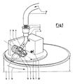
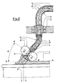
- 1 is the sliver consisting of textile fibres, coming from the outlet of the drawing frame (not shown) of the drawing facility; 2 is a stationary portion of the duct, inside whose interior the fibre sliver 1 runs. At the bend, or a large curvature radius, the fibre sliver is pressed against the inner side 2b, and, on the contrary, gets detached from the external side 2a; therefore along the bend, the fibre slivers runs with no contact with said external side; 3 is the upper driving roll, supported by a mobile frame by means of which said driving roll 3 can be lifted to reach its high position 3a in which it is spaced apart from the underlying driving roll 5.
- the underlying driving roll 5 is stationary and is anchored to the underlying plate 7 by means of a whatever anchoring element known from the prior art (not shown in the figures).
- the driving rolls 3 and 5 revolve, in order to drive the fibre sliver 1 pinched between them, around their revolution axes, the traces of which are O1 and O2; 4 is a stationary sleeve which performs the task of guiding the fibre sliver 1 through the cog disk 14.
- the axis of said sleeve 4 coincides with the axis of rotation of the rotary equipment and therefore coincides with the axis of rotation of the plate 7 and of the cog disk 14.
- the fibre sliver 1 is a short stretch of duct, which guides the fibre sliver 1 from the outlet from the sleeve 4 to the inlet to the condensing funnel 8 and it has a slightly bent shape. Inside the interior of the bent stretch 6, the fibres are slightly compressed against the inner side 6a, and get spaced apart from the external side 6b.
- Said duct stretch 6 is rotatable together with the plate 7, in that it is rigidly coupled with the condensing funnel-shaped element 8; 7 is the rotary plate which supports the whole improved device according to the present invention. Said plate is rigidly affixed to the cog disk 14 through the vertical element 26; 8 is the condensing element which guides and compacts, thanks to its converging.
- the fibre sliver 1 before this latter is pinched by the revolving driving rolls 3 and 5, which oblige said sliver 1 to deposit inside the interior of the underlying collecting can 9 according to the direction shown by the arrow 11: 12 is the arrow showing the trajectory and direction of the running fibre sliver 1 when it enters the stationary guide duct 2; 10 is the guide sleeve in order to guide the fibre sliver 1 after that this latter leaves the driving rolls 3 and 5.
- Said guide sleeve 10 has a divergent interior shape, inside which the fibre sliver expands owing to the effect of its own elasticity after having been was compressed by the rolls 3 and 5.
- Said guide sleeve 10 is additionally rigidly coupled with the rotary support plate 7; 14 is the cog disk, or cog wheel, which, by being driven to rotate by the castellated belt 20, transmits its rotary movement to the whole rotary equipment (i.e., the coyler) and, therefore, to the improved device according to the present invention;
- B-B is the trace of the plane on which the revolution axes of the rolls 3 and 5 lay.
- Said plane is substantially perpendicular to the direction 11, and forms an angle ⁇ with the plane on which the rotary support plate 7 lays, with trace A-A; 15 is the arrow which indicates the revolution direction of the whole device according to the present invention supported by the underlying plate 7.
- the rotation 15 and the simultaneous rotation 19 of the underlying collection can 9 generate the composition of two revolutionary movements, which causes the fibre sliver 1 exiting the plate 7 according to the direction 11, to deposit with an epicycloidal arrangement inside said collecting can 9;
- 18 and 16 are the protective cases, or carters, which contain the means or elements for actuating the improved device according to the present invention;
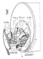
- 21 and 23 are a pair of bevel gears which transmit the revolution movement from the pinion 22 to the shaft 25.
- the pinion 22 acts as a satellite, because it is caused to revolve around the central, stationary gear wheel 24, and while it rotates around said gear wheel 24, it revolves around its own axis, thus generating a rotation which is transmitted to the shaft 25; 26 is a vertical element which rigidly connects the cog disk 14 with the rotary plate 7.
- Said vertical element 26 furthermore houses, inside its own interior, means, or elements, for motion transmission (see Figure 3);
- 30 is the double cog wheel rigidly keyed onto the revolution shaft 24 with the axis with trace C-C.
- Said double cog wheel 30 actuates simultaneously the two mutually independent castellated belts 27 and 29;
- 27 is the castellated belt which transmits the revolutionary motion to the upper driving roll 3 through the cog wheel 38 and the return/guide cog wheels 39 and 37;
- 29 is the castellated belt which transmits the revolutionary motion to the lower driving roll 5 through the cog wheel 28 and the return/guide cog wheels 34 and 36;
- 35 is the mobile frame idlingly hinged around the shaft 25, and hence capable of being angularly shifted around the axis C-C as its rotation fulcrum.
- Said mobile frame 35 is the support element which supports the driving roll 3 and hence the castellated belt 27 and the cog wheels 38, 39 and 37;
- 32 is the lever which, acting through the wheel 33, pushes upwards the mobile frame 35 in order to keep the driving roll 3 to its upper position 3a in order to deactivate the driving of the fibre sliver 1 by the coyler calender, thus causing the filling of the underlying can 9 to be discontinued;
- 32a is the trace of the lever portion in its position of "mobile frame UP", to which the "driving roll 3 in position 3a" corresponds;
- 31 is the arrow which indicates the angular shift of the lever 32, manually carried out by the attending operator, or automatically carried out by a whatever actuator.
- the device for collecting inside a can a fibre sliver leaving a drawing frame as illustrated in the hereto attached tables, can be easily understood.
- the driving rolls 3 and 5 are kept in their driving position -- and hence working position -- by a fixed-calibration spring.
- a device already known from the prior art and therefore not illustrated herein feeds a jet of compressed air, acting as an injector, in order to perform the operation of automatic introduction of the fibre sliver 1, in order to cause this latter to get engaged by the nip of the driving rolls.
- the drawing frame and the device according to the present invention are started again and the fibre sliver 1, pinched and driven by the rolls 3 and 5 -- which have already been approached again to each other by the lever 32 being returned back to its resting position -- starts depositing according to overlapping epicycloids inside the underlying collecting rotary can 9.
- the fibre sliver 1 is no longer obliged to undergo elbow-like and marked curvilinear deviations while running along more or less sharp bends, so that it is dragged by said rolls 3 and 5 with a rather low tensile stress, in that the friction caused by the contact of said fibre sliver with the walls of the duct results to be of an extremely limited value.
- the fibre sliver 1 by running along a rather straight path , as compared to the devices known from the prior art, will be exposed to a very limited friction of contact with the internal walls of the various duct stretches. All the above results in the advantage that one will have the certainty that the fibre sliver 1 will not suffer any damages, and hence that it will not undergo any accidental breakages even when the collection speed will be considerably increased in order to increase the production efficiency.
Landscapes
- Spinning Or Twisting Of Yarns (AREA)
Applications Claiming Priority (2)
| Application Number | Priority Date | Filing Date | Title |
|---|---|---|---|
| IT8920964A IT1230902B (it) | 1989-06-23 | 1989-06-23 | Perfezionamento al dispositivo per la raccolta di nastri di fibre in vasi. |
| IT2096489 | 1989-06-23 |
Publications (2)
| Publication Number | Publication Date |
|---|---|
| EP0404263A1 true EP0404263A1 (fr) | 1990-12-27 |
| EP0404263B1 EP0404263B1 (fr) | 1993-09-01 |
Family
ID=11174704
Family Applications (1)
| Application Number | Title | Priority Date | Filing Date |
|---|---|---|---|
| EP90201610A Expired - Lifetime EP0404263B1 (fr) | 1989-06-23 | 1990-06-20 | Dispositif d'emmagasinage de rubans dans des pots |
Country Status (3)
| Country | Link |
|---|---|
| EP (1) | EP0404263B1 (fr) |
| DE (1) | DE69003027D1 (fr) |
| IT (1) | IT1230902B (fr) |
Cited By (1)
| Publication number | Priority date | Publication date | Assignee | Title |
|---|---|---|---|---|
| EP0640704A1 (fr) * | 1993-08-25 | 1995-03-01 | Maschinenfabrik Rieter Ag | Machine de peignage |
Citations (6)
| Publication number | Priority date | Publication date | Assignee | Title |
|---|---|---|---|---|
| US3035311A (en) * | 1958-12-15 | 1962-05-22 | Paul C Woodbury | Anti-clogging sliver feeding and coiling apparatus |
| CH460599A (de) * | 1966-12-23 | 1968-07-31 | Schubert & Salzer Maschinen | Bandablegevorrichtung |
| DE1950773A1 (de) * | 1968-10-08 | 1970-04-30 | Warner Swasey Co | Vorrichtung zum Ablegen von Strangmaterial in Ringform |
| FR2348288A1 (fr) * | 1976-04-14 | 1977-11-10 | Krupp Gmbh | Dispositif rotatif pour deposer des rubans de fibres, en particulier des rubans d'etirage ou de carde |
| EP0175072A2 (fr) * | 1984-09-18 | 1986-03-26 | Albert Rosink, Maschinenbau Nordhorn | Tête enrouleuse pour pot de filature |
| EP0298519A1 (fr) * | 1987-07-09 | 1989-01-11 | Hollingsworth Gmbh | Procédé et dispositif d'emmagasinage d'un ruban de fibres textiles dans un pot |
-
1989
- 1989-06-23 IT IT8920964A patent/IT1230902B/it active
-
1990
- 1990-06-20 DE DE90201610T patent/DE69003027D1/de not_active Expired - Lifetime
- 1990-06-20 EP EP90201610A patent/EP0404263B1/fr not_active Expired - Lifetime
Patent Citations (6)
| Publication number | Priority date | Publication date | Assignee | Title |
|---|---|---|---|---|
| US3035311A (en) * | 1958-12-15 | 1962-05-22 | Paul C Woodbury | Anti-clogging sliver feeding and coiling apparatus |
| CH460599A (de) * | 1966-12-23 | 1968-07-31 | Schubert & Salzer Maschinen | Bandablegevorrichtung |
| DE1950773A1 (de) * | 1968-10-08 | 1970-04-30 | Warner Swasey Co | Vorrichtung zum Ablegen von Strangmaterial in Ringform |
| FR2348288A1 (fr) * | 1976-04-14 | 1977-11-10 | Krupp Gmbh | Dispositif rotatif pour deposer des rubans de fibres, en particulier des rubans d'etirage ou de carde |
| EP0175072A2 (fr) * | 1984-09-18 | 1986-03-26 | Albert Rosink, Maschinenbau Nordhorn | Tête enrouleuse pour pot de filature |
| EP0298519A1 (fr) * | 1987-07-09 | 1989-01-11 | Hollingsworth Gmbh | Procédé et dispositif d'emmagasinage d'un ruban de fibres textiles dans un pot |
Cited By (2)
| Publication number | Priority date | Publication date | Assignee | Title |
|---|---|---|---|---|
| EP0640704A1 (fr) * | 1993-08-25 | 1995-03-01 | Maschinenfabrik Rieter Ag | Machine de peignage |
| US5502875A (en) * | 1993-08-25 | 1996-04-02 | Rieter Machine Works, Ltd. | Continuous drive unit for combers, a drafting arrangement and a coiler can |
Also Published As
| Publication number | Publication date |
|---|---|
| IT8920964A0 (it) | 1989-06-23 |
| EP0404263B1 (fr) | 1993-09-01 |
| IT1230902B (it) | 1991-11-08 |
| DE69003027D1 (de) | 1993-10-07 |
Similar Documents
| Publication | Publication Date | Title |
|---|---|---|
| US3511045A (en) | Spinning apparatus having a servicing position | |
| US6568038B2 (en) | Assembly for gathering card sliver for packaging thereof in cans of various size | |
| CH630123A5 (de) | Verfahren und vorrichtung zum friktionsspinnen von garn nach dem offen-end-prinzip. | |
| US4276742A (en) | Thread-joining device | |
| EP0404263A1 (fr) | Dispositif d'emmagasinage de rubans dans des pots | |
| GB2139652A (en) | Process and apparatus for setting a friction spinning machine in operation | |
| US3732681A (en) | Open-end spinning device with an opening-up roller | |
| US4223422A (en) | Turntable for depositing a fiber sliver into a spinning can | |
| US4322942A (en) | Open-end spinning method and apparatus | |
| US4819422A (en) | Arrangement for winding a double yarn onto a cross-wound spool | |
| ITMI951438A1 (it) | Procedimento e dispositivo per la deposizione di un nastro di fibre tessili in un vaso per nastro di carda, in particolare in uno stiratoio | |
| US4228563A (en) | Drive apparatus of a can for depositing textile fibre slivers | |
| GB1577953A (en) | Open-end spinningmachines | |
| DE1510232B2 (de) | Verfahren und Vorrichtung zum Verziehen und Drehen von Faserbändern | |
| US3153272A (en) | Apparatus for the production of crimped or bulk yarn | |
| US113831A (en) | Improvement in machines for balling oakum | |
| JPH0224749B2 (fr) | ||
| US3107477A (en) | Process and apparatus for spinning fibrous materials | |
| US3468116A (en) | Method and apparatus for open end spinning | |
| EP0295731B1 (fr) | Dispositif pour produire une fausse torsion à un ruban de fibres textiles | |
| US2796725A (en) | Apparatus for simultaneous twisting and stretching, applicable to continuous machines for spinning carded wool | |
| EP3604641A1 (fr) | Dispositif et procédé pour transformer un ruban de fibres textiles en flocons | |
| EP0142273B1 (fr) | Dispositif et procédé pour la mise en route d'une machine de filature par fibres libérées | |
| US534418A (en) | Feeding mechanism foe carding machines | |
| US4107908A (en) | Method and apparatus for manufacturing a spun yarn from one or several filaments |
Legal Events
| Date | Code | Title | Description |
|---|---|---|---|
| PUAI | Public reference made under article 153(3) epc to a published international application that has entered the european phase |
Free format text: ORIGINAL CODE: 0009012 |
|
| AK | Designated contracting states |
Kind code of ref document: A1 Designated state(s): BE CH DE ES FR GB GR LI |
|
| 17P | Request for examination filed |
Effective date: 19901129 |
|
| 17Q | First examination report despatched |
Effective date: 19920812 |
|
| GRAA | (expected) grant |
Free format text: ORIGINAL CODE: 0009210 |
|
| AK | Designated contracting states |
Kind code of ref document: B1 Designated state(s): BE CH DE ES FR GB GR LI |
|
| PG25 | Lapsed in a contracting state [announced via postgrant information from national office to epo] |
Ref country code: LI Effective date: 19930901 Ref country code: GR Free format text: LAPSE BECAUSE OF FAILURE TO SUBMIT A TRANSLATION OF THE DESCRIPTION OR TO PAY THE FEE WITHIN THE PRESCRIBED TIME-LIMIT Effective date: 19930901 Ref country code: FR Effective date: 19930901 Ref country code: ES Free format text: THE PATENT HAS BEEN ANNULLED BY A DECISION OF A NATIONAL AUTHORITY Effective date: 19930901 Ref country code: DE Effective date: 19930901 Ref country code: CH Effective date: 19930901 Ref country code: BE Effective date: 19930901 |
|
| REF | Corresponds to: |
Ref document number: 69003027 Country of ref document: DE Date of ref document: 19931007 |
|
| REG | Reference to a national code |
Ref country code: CH Ref legal event code: PL |
|
| EN | Fr: translation not filed | ||
| PG25 | Lapsed in a contracting state [announced via postgrant information from national office to epo] |
Ref country code: GB Effective date: 19940620 |
|
| PLBE | No opposition filed within time limit |
Free format text: ORIGINAL CODE: 0009261 |
|
| STAA | Information on the status of an ep patent application or granted ep patent |
Free format text: STATUS: NO OPPOSITION FILED WITHIN TIME LIMIT |
|
| 26N | No opposition filed | ||
| GBPC | Gb: european patent ceased through non-payment of renewal fee |
Effective date: 19940620 |