EP0404266A1 - Buchse - Google Patents
Buchse Download PDFInfo
- Publication number
- EP0404266A1 EP0404266A1 EP90201620A EP90201620A EP0404266A1 EP 0404266 A1 EP0404266 A1 EP 0404266A1 EP 90201620 A EP90201620 A EP 90201620A EP 90201620 A EP90201620 A EP 90201620A EP 0404266 A1 EP0404266 A1 EP 0404266A1
- Authority
- EP
- European Patent Office
- Prior art keywords
- frame
- blocks
- bushing
- under operating
- operating conditions
- Prior art date
- Legal status (The legal status is an assumption and is not a legal conclusion. Google has not performed a legal analysis and makes no representation as to the accuracy of the status listed.)
- Granted
Links
- 238000007789 sealing Methods 0.000 claims abstract description 43
- 239000000463 material Substances 0.000 claims abstract description 4
- 239000002131 composite material Substances 0.000 claims abstract description 3
- 239000012858 resilient material Substances 0.000 claims abstract description 3
- 229910000831 Steel Inorganic materials 0.000 claims description 13
- 239000010959 steel Substances 0.000 claims description 13
- 238000004873 anchoring Methods 0.000 claims description 11
- 230000006835 compression Effects 0.000 claims description 10
- 238000007906 compression Methods 0.000 claims description 10
- 230000009970 fire resistant effect Effects 0.000 claims description 9
- 239000004033 plastic Substances 0.000 claims description 6
- 230000001681 protective effect Effects 0.000 claims description 3
- 230000005540 biological transmission Effects 0.000 description 5
- 239000004020 conductor Substances 0.000 description 3
- 238000006073 displacement reaction Methods 0.000 description 3
- 239000003546 flue gas Substances 0.000 description 2
- 238000009413 insulation Methods 0.000 description 2
- 230000001788 irregular Effects 0.000 description 2
- 239000002184 metal Substances 0.000 description 2
- 229910052751 metal Inorganic materials 0.000 description 2
- 238000003466 welding Methods 0.000 description 2
- OKTJSMMVPCPJKN-UHFFFAOYSA-N Carbon Chemical compound [C] OKTJSMMVPCPJKN-UHFFFAOYSA-N 0.000 description 1
- RYGMFSIKBFXOCR-UHFFFAOYSA-N Copper Chemical compound [Cu] RYGMFSIKBFXOCR-UHFFFAOYSA-N 0.000 description 1
- 230000004308 accommodation Effects 0.000 description 1
- 238000007792 addition Methods 0.000 description 1
- 230000002411 adverse Effects 0.000 description 1
- 239000011324 bead Substances 0.000 description 1
- 229910052799 carbon Inorganic materials 0.000 description 1
- 238000006243 chemical reaction Methods 0.000 description 1
- 238000010276 construction Methods 0.000 description 1
- 229910052802 copper Inorganic materials 0.000 description 1
- 239000010949 copper Substances 0.000 description 1
- 230000000694 effects Effects 0.000 description 1
- 239000011810 insulating material Substances 0.000 description 1
- 235000000396 iron Nutrition 0.000 description 1
- 238000004519 manufacturing process Methods 0.000 description 1
- 239000000779 smoke Substances 0.000 description 1
Images

Classifications
-
- F—MECHANICAL ENGINEERING; LIGHTING; HEATING; WEAPONS; BLASTING
- F16—ENGINEERING ELEMENTS AND UNITS; GENERAL MEASURES FOR PRODUCING AND MAINTAINING EFFECTIVE FUNCTIONING OF MACHINES OR INSTALLATIONS; THERMAL INSULATION IN GENERAL
- F16L—PIPES; JOINTS OR FITTINGS FOR PIPES; SUPPORTS FOR PIPES, CABLES OR PROTECTIVE TUBING; MEANS FOR THERMAL INSULATION IN GENERAL
- F16L5/00—Devices for use where pipes, cables or protective tubing pass through walls or partitions
- F16L5/02—Sealing
- F16L5/14—Sealing for double-walled or multi-channel pipes
-
- H—ELECTRICITY
- H02—GENERATION; CONVERSION OR DISTRIBUTION OF ELECTRIC POWER
- H02G—INSTALLATION OF ELECTRIC CABLES OR LINES, OR OF COMBINED OPTICAL AND ELECTRIC CABLES OR LINES
- H02G3/00—Installations of electric cables or lines or protective tubing therefor in or on buildings, equivalent structures or vehicles
- H02G3/22—Installations of cables or lines through walls, floors or ceilings, e.g. into buildings
Definitions
- the invention relates to a bushing for the sealing passage of a cable, pipe and the like through a wall, comprising a frame made of rigid material which may be sealingly inserted in an aperture provided in the wall, as well as one of more parallelepipedal blocks of a resilient material such as rubber which may be composed from two identical halves, which blocks in their composite state exhibit a bore adapted with narrow tolerances to the shape and dimensions of a cable to be passed through, which blocks can be inserted in the frame aperture so as to be a fine fit, with the two halves of every block encasing a cable, whilst in additioning tightening means with a pressure plate are present which can compress the blocks inserted in the frame aperture in the plane of this aperture such that a sealing compression is effected between the two halves of any one block, between the outer faces of mutually adjacent blocks, between the wall of the bores and the outer surface of the cables contained therein, as well as between the outer faces of the blocks and the inner walls of the frame.
- the blocks used in this known bushing are made of incompressible rubber, so that when tolerances of, say, more than 1 mm have occurred in the manufacture of the frame or the blocks, these blocks can hardly if at all be thrust into the frame, or they lie loose in the frame.
- the known bushing contains a rigid pressure plate with a thrust bolt as the principal tightening means. Threading the pressure bolt down causes a concentrated load - which in actual practice may amount to a few tons! - to be exerted upon the rigid pressure plate in order to achieve as uniform a distribution as practicable of downward directed forces acting upon the blocks inserted in the frame. By these forces all blocks in the frame should be deformed in such a way that a proper sealing of, for instance, cables passed through is ensured.
- the pressure plate used in the known bushing is provided with a recess on its edges in order that this pressure plate may invariably be a true fit inside the frame even in the event of tolerances in the frame's dimensions.
- the said recess causes an upward displacement of the rubber of the blocks which is undergoing deformation during compression. Under operating conditions of the bushing, an irregular edge of protruding rubber may appear on both edges of the pressure plate as a result.
- the known bushing is provided with rod-shaped elements which may be supported with their ends in two oppositely disposed grooves in flanges of the frame, whilst the central part of a rod-shaped element may be located in a groove of a half block such that it prevents any displacement in a transverse direction relative to the plane of the frame.
- the frame used in the known bushing is composed by, for instance, welding angle irons or metal strips together. This construction gives rise to small continuous weld fissures or beads in the angles of the frame all its adverse consequences on the sealing.
- a conflagration present on, for instance, one side of the known bushing under operating conditions reaches a temperature of about 900 °C.
- Heat from the conflagration is transmitted by - the frame - through bolts - the steel pressure plate - conductors of cables passed through - rod-shaped elements - rubber lead-through blocks.
- the object of the present invention is to provide a bushing for the optimum sealing passage of a cable, pipe and like through a wall, which bushing possesses an excellent fire resistance.
- a bushing of the type mentioned hereinbefore is characterized according to the invention in that the blocks are dimensioned such that under operating conditions of the bushing, they extend outwards on at least one side of the frame in a direction transverse to the plane of the frame, which blocks are provided with circumferential internal ribs along at least a part of their length, whilst blocks whose outer faces rest against an inner wall of the frame under operating conditions of the bushing are provided with external ribs along at least a part of the said outer faces.
- the presence of an inner and an outer profile in the form of flexible internal and external ribs ensures an optimum sealing at all times, since any tolerances in the dimensions of blocks, frame and cables to be passed through can easily be taken up by compression of these flexible rubber ribs without entailing compression or deformation of the blocks or the individual cables passed through the frame, even when the necessary compressive forces are applied.
- the outward extension present on at least one side of the frame transverse to the plane of the frame under operating conditions of the bushing has the advantage that the bushing possesses excellent fire resistance in that directions because of the increased quantity of, for instance, fire-resistant rubber.
- One embodiment of a bushing according to the invention is characterized in that blocks which are placed on top of each other under operating conditions of the bushing, are provided with a profile on their adjacent outer faces. Less sealing compression is thereby needed so as to ensure a tight sealing between adjacent blocks lying above each other during these conditions.
- a further embodiment of a bushing according to the invention is characterized in that the blocks are dimensioned such that under operating conditions of the bushing, they extend outwards on both sides of the frame in a direction transverse to the frame.
- the fire resistance of the bushing according to the invention is thereby optimized because of the symmetry between rubber masses of, say, 60 mm disposed on both sides of the frame.
- a further embodiment of a bushing according to the invention in which the tightening means comprise a rigid pressure plate with a thrust bolt is characterized in that the rigid plate is a steel plate whose edges which rest against an inner wall of the frame under operating conditions of the bushing, have been encased in a whether or not fire-resistant plastic.
- This encasement in whether or not fire-resistant plastic material preferably consists in sheathing with a whether or not fire-resisting rubber so as to prevent heat transmission through mechanical contact with the inner walls of the frame.
- the other edges of the steel pressure plate have not been sheathed in that way in order to avoid deformation of the pressure plate during compression.
- a further embodiment of a bushing according to the invention which comprises a sealing piece which may be fitted on top of the pressure plate inside the frame is characterized in that the sealing piece is dimensioned such that under operating conditions of the bushing it extends outwards on at least one side of the frame in a direction transverse to the plane of the frame and that those outer faces of the sealing plate which rest against the inner wall of the frame under operating conditions of the bushing are provided at least partly with external ribs.
- a further embodiment of a bushing according to the invention is characterized in that the sealing piece consists of at least two interconnecting parts and that its bottom face has a recess into which the steel plate can be received. As the steel plate is at it were embedded in the recess under operating conditions, no heat transmission takes place through this steel plate.
- the interconnection of the parts of the sealing piece is preferably effected by so-called dowelling, enabling the parts to be readily introduced into the uppermost zone of the frame from the outside and connected together. Dowelling has the advantage that the parts of the sealing plate remain interconnected under compressive loads during operation and therefore cannot be thrust out of the frame.
- a further embodiment of a bushing according to the invention is characterized in that the external and/or internal ribs have a substantially saw-tooth or triangular cross-section.
- internal and/or external ribs so shaped prove to afford optimum sealing.
- a further embodiment of a bushing according to the invention is characterized in that provision is made for at least one protecting plate, whether or not made of a fire-resistant plastic, which may be fitted substantially over that part of an assembly of blocks and possibly the sealing piece which projects outside on at least one side of the frame in a direction transverse to the plane of the frame.
- the said protecting plate which is preferably made of a fire-resistant rubber, serves to shield the walls of the frame from the heat of a conflagration.
- a further embodiment of a bushing according to the invention is characterized in that provision is made for at least one hood, moulded from whether or not perforated steel plate, which may be mounted on top of the protecting plate(s) to be fitted earlier.
- This hood serves to retain a protective carbon deposit formed by, for instance, rubber upon exposure to fire.
- the said perforations have, if required, been made in the hood to save weight.
- a further embodiment of a bushing according to the invention is characterized in that the design of the protective hood(s) includes a frame composed of at least two sections with upright flanges.
- a further embodiment of a bushing according to the invention is characterized in that provision is made for anchoring strips which may be inserted on at least one side of the frame in a direction parallel to the plane of the frame. Unlike the rod-shaped elements of the known bushing, these anchoring strips have the advantage that they need not be laboriously inserted into the frame at an oblique angle (from above). Oblique introduction of the rod-shaped elements into the frame is imperative, since these elements rest under operating conditions in grooves provided in flanges on the frame.
- a further embodiment of a bushing according to the invention is characterized in that the blocks have outer faces provided with grooves and that recesses are present in the protecting plate(s), if included, so that the anchoring strips can be pushed from the outside into the grooves of the blocks, whereupon the protecting plates can be fitted, allowing the anchoring strips to pass through the recesses.
- Figure 1 is a schematic view of the known bushing according to the state of the art with a frame 1 which may exhibit tolerances in dimensions in the directions indicated by arrows 2, so that the known blocks can either hardly, if at all, be pushed into the frame 1 or lie loose in frame 1.
- Figure 2 depicts the known bushing with the frame 1 of Figure 1, showing how the forces designated F are distri minded when threating down a thrust bolt 3 causes a concentrated load to be exerted upon a rigid pressure plate 4.
- Figure 3 is a side view of the known bushing according to Figure 2. Forces F acting in the directions 5 cause blocks 6 disposed in the uppermost zone of frame 1 in particular to be deformed towards the outer sides of frame 1.
- Figure 4 represents the known bushing with a sealing plate 7 according to the state of the art.
- Figure 5 depicts a detail of the known bushing designated 8 in Figure 4. Edges of the pressure plate 4 have a recess 9 in order that the pressure plate may at all times be inserted into the frame 1, also taking into account tolerances in the dimensions of frame 1. An upward movement of rubber of the blocks 6 deforming during compression, which upward movement results from forces F acting in the direction of the arrows, gives rise to an irregular edge of protruding rubber on both edges of the pressure plate 4.
- Figure 6 shows a detail of the known bushing designated 10 in Figure 4.
- the frame 1 is composed by welding strips or similar component parts together, the angles of the frame 1 may be liable to small continuous weld fissures 11 which cannot be sealed by non-compressible blocks 12.
- Figure 7 represents a detail of the known bushing designated 13 in Figure 4. For reasons mentioned herein before, no adequate sealing proves feasible in actual practice between rows of blocks 6 between which a rod-shaped element 14 is confined.
- Figure 8 depicts a detail of the known bushing designated 15 in Figure 4.
- the blocks 6 disposed in the uppermost zone of frame 1 absorb substantially the entire downward directed pressure exerted by the pressure plate 4 and the thrust bolt 3, a cable 16 passed through block 12 is not adequately sealed since, failing sufficient downward directed pressure on the spot, the halves of block 12 are not compressed sufficiently tight under operating conditions, so that continuous interfacial fissures persist between the said halves.
- Figure 9 shows a plan and a front view of the sealing plate of Figure 4.
- the forces indicated by F and acting in the direction of the arrows cause a lateral deformation 17 relative to frame 1 (denoted by dotted lines) of the blocks 6 disposed in the uppermost zone of frame 1.
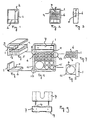
- Figures 10 and 11 show one half 19 of a parallelepipedal block 20 and several parallelepipedal blocks 20, respectively, which are dimensioned such that, under operating conditions of the bushing according to the invention, they project outside on both sides of a frame of the bushing in a direction transverse to the plane of the frame over distances 21 (say, 60 mm at a frame width also of 60 mm, so that the overall width is 180 mm).
- the blocks 20 are provided with circumferential internal ribs 22 over at least a part of their length, whilst blocks 20 whose outer faces rest against an inner wall of the frame under operating conditions of the bushing according to the invention are provided ate least partly with external ribs 23 on the said outer faces.
- Figure 13 represents a sealing piece 24 according to the invention which is composed of two halves that can be interconnected through dowelling.
- This sealing piece 24 is also dimensioned such that, under operating conditions of the bushing according to the invention, it projects outside over distances 21 on both sides of the frame in a direction transverse to the plane of the frame.
- Those outer faces of the sealing piece 24 which again under operating conditions rest against an inner wall of the frame are provided at least partly with external ribs 23.
- the sealing piece 24 also contains a recess 25 into which a pressure plate 26 of Figure 12 can be received. As a result, no heat transmission through the pressure plate 26 and the "invulcanised" bolts takes place under operating conditions of the bushing.
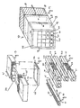
- Figure 14 is a greatly simplified view of a bushing 27 according to the invention with the frame 28, the blocks 20, the sealing piece 24, protecting plates 29 made of a fire-resistant plastic and a hood 18 which for the sake of simplicity of the drawing is shown on one side only of the bushing 27.
- the blocks 20 of Figures 10 and 11 have grooves 30 and the protecting plates 29 are provided with recesses 31 such that anchoring strips (not shown) can be pushed from the outside into the grooves 30, whereupon the protecting plates 29 can be introduced, allowing the anchoring strips to pass through the recesses 31.
- the bushing 27 according to the invention has the highly significant advantage that no heat transmission whatever can take place through the frame 28, the pressure plate 26, the sealing piece 24, the anchoring strips and the through bolts, because all metal parts have been screened by fire-resistant rubber.
- Figures 15a - 15c show an embodiment of one half of a parallelepipedal block of a bushing according to the invention in side view, in plan view and in cross section (along the line A-A of Figure 15a), respectively.
- This embodiment corresponds to the ones of the Figures 1 - 14, on the understanding that now blocks which are placed on top of each other under operating conditions of the bushing, are provided with a profile 32 on their adjacent outer faces.
- the presence of these profiles 32 ensures an optimum sealing at all times, since any tolerances in the dimensions of blocks can easily be taken up by compression of these profiles 32.
- the presence of these profiles 32 ensures that no deformation of rubber occurs and that, as already mentioned, less sealing compression is needed.
Landscapes
- Engineering & Computer Science (AREA)
- General Engineering & Computer Science (AREA)
- Architecture (AREA)
- Civil Engineering (AREA)
- Structural Engineering (AREA)
- Mechanical Engineering (AREA)
- Installation Of Indoor Wiring (AREA)
- Gasket Seals (AREA)
- Manufacturing Of Micro-Capsules (AREA)
- Curing Cements, Concrete, And Artificial Stone (AREA)
- Non-Silver Salt Photosensitive Materials And Non-Silver Salt Photography (AREA)
- Connector Housings Or Holding Contact Members (AREA)
- Saccharide Compounds (AREA)
- Securing Of Glass Panes Or The Like (AREA)
Priority Applications (1)
| Application Number | Priority Date | Filing Date | Title |
|---|---|---|---|
| AT90201620T ATE86724T1 (de) | 1989-06-23 | 1990-06-21 | Buchse. |
Applications Claiming Priority (2)
| Application Number | Priority Date | Filing Date | Title |
|---|---|---|---|
| NL8901597 | 1989-06-23 | ||
| NL8901597A NL8901597A (nl) | 1989-06-23 | 1989-06-23 | Doorvoerinrichting. |
Publications (2)
| Publication Number | Publication Date |
|---|---|
| EP0404266A1 true EP0404266A1 (de) | 1990-12-27 |
| EP0404266B1 EP0404266B1 (de) | 1993-03-10 |
Family
ID=19854897
Family Applications (1)
| Application Number | Title | Priority Date | Filing Date |
|---|---|---|---|
| EP90201620A Expired - Lifetime EP0404266B1 (de) | 1989-06-23 | 1990-06-21 | Buchse |
Country Status (7)
| Country | Link |
|---|---|
| US (1) | US5108060A (de) |
| EP (1) | EP0404266B1 (de) |
| JP (1) | JP2848676B2 (de) |
| AT (1) | ATE86724T1 (de) |
| DE (1) | DE69001047T2 (de) |
| NL (1) | NL8901597A (de) |
| NO (1) | NO902754L (de) |
Cited By (4)
| Publication number | Priority date | Publication date | Assignee | Title |
|---|---|---|---|---|
| WO1995031026A1 (en) * | 1994-05-04 | 1995-11-16 | Beele Engineering B.V. | Bushing |
| GB2337870A (en) * | 1998-04-29 | 1999-12-01 | Nokia Telecommunications Oy | Modular cable entry system |
| NL1016703C2 (nl) * | 2000-11-24 | 2002-05-27 | Beele Eng Bv | Doorvoerinrichting. |
| EP2593700A1 (de) | 2010-07-14 | 2013-05-22 | Mora Contract Manufacturing AB | Dichtungsmodul zur rundumdichtung einer verlängerten schaltung |
Families Citing this family (27)
| Publication number | Priority date | Publication date | Assignee | Title |
|---|---|---|---|---|
| DE9211740U1 (de) * | 1992-09-01 | 1992-11-12 | Jürgen Albers GmbH, 6293 Löhnberg | Leitungseinführungsplatte |
| US6241199B1 (en) | 1999-03-02 | 2001-06-05 | Sioux Chief Manufacturing Company, Inc. | Protective insulating sleeve for plumbing installations |
| DE19929722A1 (de) * | 1999-06-24 | 2001-01-04 | Dts Pro Sys Gmbh | Verfahren zum Aufbau einer Brandschutzdurchführung für Kabel |
| DE10150075A1 (de) * | 2001-10-10 | 2003-04-17 | Roxtec Ingenieur Gmbh | Modulare Schottung zur dichten Durchführung von Kabeln und Rohrleitungen durch Bauteile aller Art (mit nachweisbarer Dichte) |
| US7418562B2 (en) * | 2002-08-29 | 2008-08-26 | International Business Machines Corporation | Apparatus and method to assign one or more storage construct names to a logical volume |
| DE10313989B4 (de) * | 2003-03-27 | 2012-07-12 | Murrplastik Systemtechnik Gmbh | Kabeldurchführungsvorrichtung |
| SE526574C2 (sv) * | 2003-06-17 | 2005-10-11 | Roxtec Ab | Modul och ram för kabelgenomföringar eller liknande |
| DE102004032870B3 (de) * | 2004-07-07 | 2006-02-23 | Hilti Ag | Vorrichtung zur Abschottung einer Durchführung in einem Bauteil, insbesondere zur Abschottung einer Wanddurchführung |
| ES2324825T3 (es) * | 2004-08-24 | 2009-08-17 | Mct Brattberg Ab | Disposicion de proteccion contra incendios para instalacion en un tabique. |
| DE102005056215B4 (de) * | 2005-11-25 | 2013-05-23 | Rittal Gmbh & Co. Kg | Vorrichtung zum Führen von Kabeln oder Leitungen |
| DE102005056214B3 (de) * | 2005-11-25 | 2007-06-21 | Rittal Gmbh & Co. Kg | Vorrichtung zum Führen von Kabeln oder Leitungen |
| ES2394649T3 (es) | 2006-03-20 | 2013-02-04 | Beele Engineering B.V. | Sistema para sellar dinámicamente un manguito de canalización a través del cual se extiende un tubo o cable |
| SE533744C2 (sv) * | 2009-02-04 | 2010-12-21 | Roxtec Ab | Rör- eller kabelgenomföring med modulariserade moduler |
| ES2392791T3 (es) * | 2010-05-25 | 2012-12-13 | Beele Engineering B.V. | Un conjunto y un procedimiento para proporcionar un sistema de sellado en una abertura |
| DE102010037463A1 (de) * | 2010-09-10 | 2012-03-15 | Phoenix Contact Gmbh & Co. Kg | Rahmen eines Kabeleinführungssystems und Kabeltülle hierfür |
| DE102011054294A1 (de) * | 2011-10-07 | 2013-04-11 | Phoenix Contact Gmbh & Co. Kg | Kabeldurchführung und Verfahren zur Montage einer Kabeldurchführung |
| ES2626753T3 (es) | 2012-08-30 | 2017-07-25 | Beele Engineering B.V. | Sistema de estanqueidad para un espacio anular |
| NL2010304C2 (en) * | 2013-02-14 | 2014-08-18 | Beele Eng Bv | System for sealingly holding cables which extend through an opening. |
| NL1040892B1 (en) * | 2014-07-16 | 2016-08-16 | Beele Eng Bv | System for holding in a conduit cables or ducts with different diameters. |
| SE539322C2 (en) * | 2015-11-18 | 2017-07-04 | Roxtec Ab | Transition and module |
| CN113995532B (zh) * | 2016-07-14 | 2024-11-01 | 直观外科手术操作公司 | 器械冲洗系统 |
| DE102018218426A1 (de) * | 2018-10-29 | 2020-04-30 | Icotek Project Gmbh & Co. Kg | Kabeldurchführung |
| EP4044954A1 (de) | 2019-10-17 | 2022-08-24 | Intuitive Surgical Operations, Inc. | Chirurgisches werkzeug mit ineinandergeschachtelten schaftrohren |
| US20220224097A1 (en) * | 2021-01-14 | 2022-07-14 | Quanta Computer Inc. | Cable-entry device for an electronic chassis |
| SE545653C2 (en) * | 2021-06-08 | 2023-11-28 | Roxtec Ab | A transit device for leading one or more cables and/or pipes through an opening in a partition |
| US12117114B2 (en) * | 2021-09-09 | 2024-10-15 | Fast Valve Llc | Cleanroom wall passthrough |
| SE546693C2 (en) * | 2023-06-15 | 2025-02-11 | Roxtec Ab | A transit device and system for leading cables or pipes through a partition and use thereof |
Citations (3)
| Publication number | Priority date | Publication date | Assignee | Title |
|---|---|---|---|---|
| EP0183300A1 (de) * | 1984-11-30 | 1986-06-04 | Lycab Ab | Abdichtungssystem |
| GB2186440A (en) * | 1986-02-11 | 1987-08-12 | Hawke Cable Glands Ltd | Transit for cables and pipes |
| DE3809885C1 (de) * | 1988-03-24 | 1989-05-03 | Plastoform Gmbh & Co Kg, 4973 Vlotho, De |
Family Cites Families (13)
| Publication number | Priority date | Publication date | Assignee | Title |
|---|---|---|---|---|
| US2732226A (en) * | 1956-01-24 | Brattberg | ||
| US3282544A (en) * | 1963-03-11 | 1966-11-01 | Lyckeaborgs Bruk Ab | Tight lead-through inlet frame device for electrical lines |
| US3489440A (en) * | 1966-04-18 | 1970-01-13 | Lyckeaborgs Bruk Ab | Tight lead-through inlet frame device |
| DE2429049A1 (de) * | 1974-06-18 | 1976-01-08 | Hauff Technik Kg | Dichte wanddurchfuehrung in einem rahmen |
| US4093818A (en) * | 1974-12-20 | 1978-06-06 | Dufaylite Developments Limited | Fire-protective cellular service ducting |
| DE2632325C3 (de) * | 1976-07-17 | 1983-12-29 | Neuwalzwerk Bettermann Ohg, 5750 Menden | Brandschutzeinrichtung für eine Kabeldurchführung |
| US4086736A (en) * | 1976-12-16 | 1978-05-02 | Daniel International Corporation | Fire and liquid seals for pipes and conduits and method of forming same |
| NO159759C (no) * | 1985-08-12 | 1989-02-01 | Norsk Kabelfabrikk A S | Fremgangsm te til fremstilling av gass- og vanntettgjennomfoeringer og kabelgjennomfoering fremstilt ved fremgangsm ten. |
| GB2186442B (en) * | 1986-02-11 | 1990-03-14 | Hawke Cable Glands Ltd | Improved transit for cables and pipes |
| JPH0231657Y2 (de) * | 1986-10-15 | 1990-08-27 | ||
| GB2204922B (en) * | 1987-05-06 | 1990-08-15 | Hawke Cable Glands Ltd | Improved transit for cables and pipes |
| DE3727160C1 (de) * | 1987-08-14 | 1988-09-08 | Plastoform Gmbh & Co Kg | Durchfuehrung fuer Leitungen durch eine Wandoeffnung |
| JP6355285B2 (ja) | 2017-04-11 | 2018-07-11 | 株式会社ユピテル | 車両用システム及びプログラム |
-
1989
- 1989-06-23 NL NL8901597A patent/NL8901597A/nl not_active Application Discontinuation
-
1990
- 1990-06-21 EP EP90201620A patent/EP0404266B1/de not_active Expired - Lifetime
- 1990-06-21 NO NO90902754A patent/NO902754L/no unknown
- 1990-06-21 AT AT90201620T patent/ATE86724T1/de not_active IP Right Cessation
- 1990-06-21 DE DE9090201620T patent/DE69001047T2/de not_active Expired - Fee Related
- 1990-06-22 US US07/542,381 patent/US5108060A/en not_active Expired - Fee Related
- 1990-06-25 JP JP2168155A patent/JP2848676B2/ja not_active Expired - Lifetime
Patent Citations (3)
| Publication number | Priority date | Publication date | Assignee | Title |
|---|---|---|---|---|
| EP0183300A1 (de) * | 1984-11-30 | 1986-06-04 | Lycab Ab | Abdichtungssystem |
| GB2186440A (en) * | 1986-02-11 | 1987-08-12 | Hawke Cable Glands Ltd | Transit for cables and pipes |
| DE3809885C1 (de) * | 1988-03-24 | 1989-05-03 | Plastoform Gmbh & Co Kg, 4973 Vlotho, De |
Cited By (8)
| Publication number | Priority date | Publication date | Assignee | Title |
|---|---|---|---|---|
| WO1995031026A1 (en) * | 1994-05-04 | 1995-11-16 | Beele Engineering B.V. | Bushing |
| NL9400745A (nl) * | 1994-05-04 | 1995-12-01 | Beele Eng Bv | Doorvoerinrichting. |
| GB2337870A (en) * | 1998-04-29 | 1999-12-01 | Nokia Telecommunications Oy | Modular cable entry system |
| NL1016703C2 (nl) * | 2000-11-24 | 2002-05-27 | Beele Eng Bv | Doorvoerinrichting. |
| WO2002043212A1 (en) * | 2000-11-24 | 2002-05-30 | Beele Engineering B.V. | Bushing |
| US7005579B2 (en) | 2000-11-24 | 2006-02-28 | Beele Engineering B.V. | Bushing |
| EP2593700A1 (de) | 2010-07-14 | 2013-05-22 | Mora Contract Manufacturing AB | Dichtungsmodul zur rundumdichtung einer verlängerten schaltung |
| EP2593700A4 (de) * | 2010-07-14 | 2013-11-27 | Mora Contract Mfg Ab | Dichtungsmodul zur rundumdichtung einer verlängerten schaltung |
Also Published As
| Publication number | Publication date |
|---|---|
| DE69001047T2 (de) | 1993-06-17 |
| DE69001047D1 (de) | 1993-04-15 |
| NO902754L (no) | 1990-12-27 |
| NL8901597A (nl) | 1991-01-16 |
| US5108060A (en) | 1992-04-28 |
| EP0404266B1 (de) | 1993-03-10 |
| JP2848676B2 (ja) | 1999-01-20 |
| JPH03129179A (ja) | 1991-06-03 |
| ATE86724T1 (de) | 1993-03-15 |
| NO902754D0 (no) | 1990-06-21 |
Similar Documents
| Publication | Publication Date | Title |
|---|---|---|
| EP0404266B1 (de) | Buchse | |
| US4061344A (en) | Fitting for penetration through fire rated barriers | |
| NL8001124A (nl) | Brandwerend stelsel voor elektrische kabels. | |
| US4291514A (en) | High temperature enclosures | |
| KR101925453B1 (ko) | 화재확산방지 기능을 갖는 케이블 트레이 | |
| EP0225107B1 (de) | Feuerhemmende Mauerdurchführung für elektrische Leitungen | |
| EP0797856B1 (de) | Kabeldurchführung | |
| KR101608793B1 (ko) | 승강도어 | |
| US5187910A (en) | Fire barrier system | |
| RU2644519C1 (ru) | Пожаровзрывозащитная дверь | |
| US4151693A (en) | Refractory/insulating modules and method of making same | |
| US4902851A (en) | Combination protection room | |
| CN113163942B (zh) | 存档结构 | |
| KR102305547B1 (ko) | 보강부재가 내부에 구비된 방화차열 및 단열 결로방지형 방화문 | |
| GB2315288A (en) | Explosion-resistant wall | |
| JPH0581582U (ja) | プラスチックパイプの防火区画体貫通部の防火措置構造 | |
| KR102723672B1 (ko) | 에어로젤을 이용한 단열 방화문 | |
| US5110006A (en) | Heat insulation system for surfaces along which a hot gas stream is conducted | |
| EP0063007A1 (de) | Montageteile zur Rohrisolierung | |
| JP3765383B2 (ja) | 可燃性長尺物貫通部防火処置用箱型枠体 | |
| JP2020507716A (ja) | 配管用モジュール式断熱構造体 | |
| CN218643606U (zh) | 一种钢板墙模块及防火隔热钢板防护墙 | |
| CN216134245U (zh) | 一种可防火的集成式电缆密封夹具 | |
| WO2019116223A1 (en) | Cable transit module | |
| WO2006021567A1 (en) | Fire-protection arrangement for an installation in a partition |
Legal Events
| Date | Code | Title | Description |
|---|---|---|---|
| PUAI | Public reference made under article 153(3) epc to a published international application that has entered the european phase |
Free format text: ORIGINAL CODE: 0009012 |
|
| AK | Designated contracting states |
Kind code of ref document: A1 Designated state(s): AT BE DE FR GB IT NL SE |
|
| 17P | Request for examination filed |
Effective date: 19910104 |
|
| 17Q | First examination report despatched |
Effective date: 19910717 |
|
| GRAA | (expected) grant |
Free format text: ORIGINAL CODE: 0009210 |
|
| AK | Designated contracting states |
Kind code of ref document: B1 Designated state(s): AT BE DE FR GB IT NL SE |
|
| PG25 | Lapsed in a contracting state [announced via postgrant information from national office to epo] |
Ref country code: IT Free format text: LAPSE BECAUSE OF FAILURE TO SUBMIT A TRANSLATION OF THE DESCRIPTION OR TO PAY THE FEE WITHIN THE PRE;WARNING: LAPSES OF ITALIAN PATENTS WITH EFFECTIVE DATE BEFORE 2007 MAY HAVE OCCURRED AT ANY TIME BEFORE 2007. THE CORRECT EFFECTIVE DATE MAY BE DIFFERENT FROM THE ONE RECORDED.SCRIBED TIME-LIMIT Effective date: 19930310 Ref country code: FR Effective date: 19930310 Ref country code: AT Effective date: 19930310 |
|
| REF | Corresponds to: |
Ref document number: 86724 Country of ref document: AT Date of ref document: 19930315 Kind code of ref document: T |
|
| REF | Corresponds to: |
Ref document number: 69001047 Country of ref document: DE Date of ref document: 19930415 |
|
| EN | Fr: translation not filed | ||
| PLBE | No opposition filed within time limit |
Free format text: ORIGINAL CODE: 0009261 |
|
| STAA | Information on the status of an ep patent application or granted ep patent |
Free format text: STATUS: NO OPPOSITION FILED WITHIN TIME LIMIT |
|
| 26N | No opposition filed | ||
| EAL | Se: european patent in force in sweden |
Ref document number: 90201620.3 |
|
| PGFP | Annual fee paid to national office [announced via postgrant information from national office to epo] |
Ref country code: GB Payment date: 20000621 Year of fee payment: 11 |
|
| PGFP | Annual fee paid to national office [announced via postgrant information from national office to epo] |
Ref country code: SE Payment date: 20000627 Year of fee payment: 11 |
|
| PGFP | Annual fee paid to national office [announced via postgrant information from national office to epo] |
Ref country code: NL Payment date: 20000630 Year of fee payment: 11 |
|
| PGFP | Annual fee paid to national office [announced via postgrant information from national office to epo] |
Ref country code: DE Payment date: 20000703 Year of fee payment: 11 |
|
| PGFP | Annual fee paid to national office [announced via postgrant information from national office to epo] |
Ref country code: BE Payment date: 20000814 Year of fee payment: 11 |
|
| PG25 | Lapsed in a contracting state [announced via postgrant information from national office to epo] |
Ref country code: GB Free format text: LAPSE BECAUSE OF NON-PAYMENT OF DUE FEES Effective date: 20010621 |
|
| PG25 | Lapsed in a contracting state [announced via postgrant information from national office to epo] |
Ref country code: SE Free format text: LAPSE BECAUSE OF NON-PAYMENT OF DUE FEES Effective date: 20010622 |
|
| PG25 | Lapsed in a contracting state [announced via postgrant information from national office to epo] |
Ref country code: BE Free format text: LAPSE BECAUSE OF NON-PAYMENT OF DUE FEES Effective date: 20010630 |
|
| BERE | Be: lapsed |
Owner name: CSD INTERNATIONAL B.V. Effective date: 20010630 |
|
| PG25 | Lapsed in a contracting state [announced via postgrant information from national office to epo] |
Ref country code: NL Free format text: LAPSE BECAUSE OF NON-PAYMENT OF DUE FEES Effective date: 20020101 |
|
| EUG | Se: european patent has lapsed |
Ref document number: 90201620.3 |
|
| GBPC | Gb: european patent ceased through non-payment of renewal fee |
Effective date: 20010621 |
|
| NLV4 | Nl: lapsed or anulled due to non-payment of the annual fee |
Effective date: 20020101 |
|
| PG25 | Lapsed in a contracting state [announced via postgrant information from national office to epo] |
Ref country code: DE Free format text: LAPSE BECAUSE OF NON-PAYMENT OF DUE FEES Effective date: 20020403 |