EP0404335B1 - Strahlungsgerät - Google Patents
Strahlungsgerät Download PDFInfo
- Publication number
- EP0404335B1 EP0404335B1 EP90305268A EP90305268A EP0404335B1 EP 0404335 B1 EP0404335 B1 EP 0404335B1 EP 90305268 A EP90305268 A EP 90305268A EP 90305268 A EP90305268 A EP 90305268A EP 0404335 B1 EP0404335 B1 EP 0404335B1
- Authority
- EP
- European Patent Office
- Prior art keywords
- channels
- stationary
- annular portion
- fluid
- cooling fluid
- Prior art date
- Legal status (The legal status is an assumption and is not a legal conclusion. Google has not performed a legal analysis and makes no representation as to the accuracy of the status listed.)
- Expired - Lifetime
Links
- 230000005855 radiation Effects 0.000 title claims description 22
- 239000012809 cooling fluid Substances 0.000 claims description 33
- 239000012530 fluid Substances 0.000 claims description 28
- 238000001816 cooling Methods 0.000 claims description 16
- 238000004891 communication Methods 0.000 claims description 5
- 238000007789 sealing Methods 0.000 claims 5
- 238000001514 detection method Methods 0.000 claims 2
- 230000013011 mating Effects 0.000 claims 2
- 238000003325 tomography Methods 0.000 claims 1
- 239000003921 oil Substances 0.000 description 13
- 239000002826 coolant Substances 0.000 description 6
- 230000008901 benefit Effects 0.000 description 4
- 238000004378 air conditioning Methods 0.000 description 3
- 238000010894 electron beam technology Methods 0.000 description 3
- 230000008878 coupling Effects 0.000 description 2
- 238000010168 coupling process Methods 0.000 description 2
- 238000005859 coupling reaction Methods 0.000 description 2
- 230000004907 flux Effects 0.000 description 2
- 238000003384 imaging method Methods 0.000 description 2
- 230000003993 interaction Effects 0.000 description 2
- 239000007788 liquid Substances 0.000 description 2
- 238000004804 winding Methods 0.000 description 2
- LFQSCWFLJHTTHZ-UHFFFAOYSA-N Ethanol Chemical compound CCO LFQSCWFLJHTTHZ-UHFFFAOYSA-N 0.000 description 1
- NINIDFKCEFEMDL-UHFFFAOYSA-N Sulfur Chemical compound [S] NINIDFKCEFEMDL-UHFFFAOYSA-N 0.000 description 1
- 239000005864 Sulphur Substances 0.000 description 1
- 238000002591 computed tomography Methods 0.000 description 1
- 238000013480 data collection Methods 0.000 description 1
- 230000003247 decreasing effect Effects 0.000 description 1
- 230000005684 electric field Effects 0.000 description 1
- 239000007789 gas Substances 0.000 description 1
- 239000011521 glass Substances 0.000 description 1
- 230000017525 heat dissipation Effects 0.000 description 1
- -1 hexafluoride Substances 0.000 description 1
- 230000000977 initiatory effect Effects 0.000 description 1
- 238000003475 lamination Methods 0.000 description 1
- 238000000034 method Methods 0.000 description 1
- 230000002085 persistent effect Effects 0.000 description 1
- 238000002601 radiography Methods 0.000 description 1
- 239000003507 refrigerant Substances 0.000 description 1
- 238000005096 rolling process Methods 0.000 description 1
- 238000005070 sampling Methods 0.000 description 1
- 230000029305 taxis Effects 0.000 description 1
- WFKWXMTUELFFGS-UHFFFAOYSA-N tungsten Chemical compound [W] WFKWXMTUELFFGS-UHFFFAOYSA-N 0.000 description 1
- 229910052721 tungsten Inorganic materials 0.000 description 1
- 239000010937 tungsten Substances 0.000 description 1
- 239000002918 waste heat Substances 0.000 description 1
- XLYOFNOQVPJJNP-UHFFFAOYSA-N water Substances O XLYOFNOQVPJJNP-UHFFFAOYSA-N 0.000 description 1
Images



Classifications
-
- A—HUMAN NECESSITIES
- A61—MEDICAL OR VETERINARY SCIENCE; HYGIENE
- A61B—DIAGNOSIS; SURGERY; IDENTIFICATION
- A61B6/00—Apparatus or devices for radiation diagnosis; Apparatus or devices for radiation diagnosis combined with radiation therapy equipment
- A61B6/02—Arrangements for diagnosis sequentially in different planes; Stereoscopic radiation diagnosis
- A61B6/03—Computed tomography [CT]
- A61B6/032—Transmission computed tomography [CT]
- A61B6/035—Mechanical aspects of CT
-
- A—HUMAN NECESSITIES
- A61—MEDICAL OR VETERINARY SCIENCE; HYGIENE
- A61B—DIAGNOSIS; SURGERY; IDENTIFICATION
- A61B6/00—Apparatus or devices for radiation diagnosis; Apparatus or devices for radiation diagnosis combined with radiation therapy equipment
- A61B6/02—Arrangements for diagnosis sequentially in different planes; Stereoscopic radiation diagnosis
- A61B6/03—Computed tomography [CT]
- A61B6/032—Transmission computed tomography [CT]
-
- A—HUMAN NECESSITIES
- A61—MEDICAL OR VETERINARY SCIENCE; HYGIENE
- A61B—DIAGNOSIS; SURGERY; IDENTIFICATION
- A61B6/00—Apparatus or devices for radiation diagnosis; Apparatus or devices for radiation diagnosis combined with radiation therapy equipment
- A61B6/44—Constructional features of apparatus for radiation diagnosis
- A61B6/4488—Means for cooling
-
- A—HUMAN NECESSITIES
- A61—MEDICAL OR VETERINARY SCIENCE; HYGIENE
- A61B—DIAGNOSIS; SURGERY; IDENTIFICATION
- A61B6/00—Apparatus or devices for radiation diagnosis; Apparatus or devices for radiation diagnosis combined with radiation therapy equipment
- A61B6/56—Details of data transmission or power supply, e.g. use of slip rings
-
- A—HUMAN NECESSITIES
- A61—MEDICAL OR VETERINARY SCIENCE; HYGIENE
- A61B—DIAGNOSIS; SURGERY; IDENTIFICATION
- A61B6/00—Apparatus or devices for radiation diagnosis; Apparatus or devices for radiation diagnosis combined with radiation therapy equipment
- A61B6/40—Arrangements for generating radiation specially adapted for radiation diagnosis
- A61B6/4021—Arrangements for generating radiation specially adapted for radiation diagnosis involving movement of the focal spot
Definitions
- This invention relates to radiation apparatus.
- the invention relates to the radiography art and finds particular application in conjunction with computerized tomographic (CT) scanners and will be described with particular reference thereto.
- CT computerized tomographic
- the present invention may also find application in conjunction with other radiation apparatus, i.e. radiation treatment apparatus, and other imaging apparatus.
- tomographic scanners have commonly included a floor-mounted frame assembly which remains stationary during a scan.
- An x-ray tube is mounted to a rotatable frame assembly which rotates around a patient receiving examination region during the scan. Radiation from the x-ray tube traverses the patient receiving region and impinges upon an array of radiation detectors. From the radiation data sampled by the detectors and the position of the x-ray tube during each sampling, a tomographic image of one or more slices through the patient is reconstructed.
- An x-ray tube generates x-rays by directing a high energy electron beam against a tungsten target.
- One of the persistent problems in CT scanners and other radiographic apparatus is dissipating the waste heat created while generating x-rays.
- the anode turns so that the high energy electron beam only dwells a fraction of a second at a time on any point on the anode.
- the x-ray tube is jacketed with a lead lined housing. A cooling oil is circulated between the glass envelope of the x-ray tube and the housing to remove additional heat.
- the x-ray tube rotates in one direction during a scan and returns in the other direction for the next scan.
- Such scanners are normally limited to about 360° of rotation.
- the single rotation enables the hot cooling oil to be conveyed from the rotating frame by flexible hoses to a non-rotating heat exchanger.
- Accommodating the cooling oil-carrying hoses is a space consumptive handling problem.
- the heat exchanger is commonly a radiator disposed within the CT scanner housing that is cooled by fans which blow room air through the heat exchanger and back into the room. This places an extra load on the room air conditioning system.
- the cooling oil is circulated to a radiator or other air-oil heat exchanger that is mounted on the rotating frame portion.
- This alleviates the hose handling problems and enables the x-ray tube to rotate a plurality of times, e.g. a continuous rotate scanner.
- accommodating the size and weight of the heat exchanger in the tight space constraints of the rotating frame is difficult.
- air passes through the heat exchanger cooling the oil. The heated air that is discharged into the room that contains the CT scanner again places a greater load on the room air conditioning system.
- One of the limiting factors on the speed of a CT scan is the amount of x-rays produced by the x-ray tube.
- the tube must irradiate each detector for a sufficient duration that each detector receives the minimum total flux needed to reconstruct a good contrast image.
- Lower power tubes require the tube to dwell or focus longer on each detector.
- Larger, more powerful x-ray tubes supply the minimum flux more quickly, allowing the speed of rotation to be increased, hence the scan time decreased.
- the x-ray tubes become more powerful, more heat is generated. More heat is also generated in continuous rotate scanners in which the tube remains "on" during several consecutive rotations for multislice imaging.
- a radiation apparatus comprising a radiation source mounted on a frame for rotation relative to a stationary frame charaterised by a fluidic slip ring for providing a cooling fluid communication between the rotatable frame and the stationary frame and a cooling fluid calculating means for circulating a cooling fluid through the fluidic slip ring from the rotatable frame to the stationary frame and vice-versa.
- One advantage of the present invention is that it enables the effective cooling of a radiation source.
- Another advantage of the present invention is that it enables heat from the radiation source to be dissipated externally of the apparatus and the apparatus control room.
- Another advantage of the present invention is that it facilitates the use of high power radiation sources.
- Another advantage of the present invention is that it enables the x-ray tube of a CT scanner to rotate continuously.
- EP-A-0225964 discloses a cooling system for relatively movable components, such as a rotor seated for rotation with respect to a stationary component, including a sealed channel in the stationary component disposed between the stationary component and the movable component, and an evaporator disposed within the sealed channel.
- the channel is filled with coolant, such as alcohol or oil, which is circulated by a pump in a closed circulation path. Heat is thereby conveyed from the system components to be cooled to the evaporator, and from the evaporator to a location where the heat can be dissipated without disturbing operation of the device.
- the cooling system is suitable for use, for example, in a computer tomograph for cooling the radiation detector.
- the apparatus comprises a CT scanner which includes a floor-mounted or stationary frame portion A whose position remains fixed during data collection.
- An x-ray tube B is rotatably mounted by a bearing and fluidic slip ring assembly C for continuous rotation.
- the fluidic slip ring passes a cooling fluid, such as oil, water, sulphur, hexafluoride, and other liquids and gases, between an externally mounted chilling unit or heat exchanger D and the rotatably mounted x-ray tube B.
- the stationary frame portion A includes a cylinder 10 that defines a patient receiving examination region 12 therein.
- An array of radiation detectors 14 are disposed concentrically around the patient receiving region.
- the stationary frame with the rotating frame can be canted or tipped to scan slices at selectable angles.
- a control console 16 contains an image reconstructing means 18 for reconstructing an image representation of output signals from the detector array 14.
- a video monitor 20 converts the reconstructed image representation into a man-readable display.
- the console also includes appropriate tape and disk recording means for archiving image representations, performing image enhancements, and the like.
- Various control functions, such as initiating a scan, selecting among different types of scans, calibrating the system, and the like are also performed at the control panel.
- the x-ray tube B is enclosed in an oil-filled housing 30 that has an x-ray permeable window directed toward the patient receiving region 12.
- a motor rotates an anode, such as a seven inch anode, in the plane of the patient receiving region and the x-ray transmissive window.
- An oil pump circulates the oil from the housing through a heat exchanger 32. The heat exchanger transfers heat from the oil to a liquid coolant.
- An electron beam emitted by a cathode strikes the rotating anode adjacent the window such that x-rays are emitted through the window.
- Appropriate x-ray collimators focus the radiation into one or more planar beams, or the like, as are conventional in the art.
- a shutter under control from the console selectively gates the beam on and off to control patient dosage.
- Electrical power from the console is conveyed to an electrical slip ring 34 that is mounted in association with the bearing and fluidic slip ring assembly C.
- a high voltage power supply is mounted for rotation in association with the x-ray tube for converting the lower voltage conveyed across the electrical slip ring to the appropriate high voltages for operating the x-ray tube.
- the x-ray tube B is mounted on a rotating x-ray tube support or frame 40.
- the rotating frame assembly includes an annular ring portion 42 which is connected with a rotating race 44 of a large bearing that surrounds the patient receiving region.
- the bearing also includes a stationary race 46 that is mounted to an annular tubular structure of the stationary frame assembly A.
- the bearing also includes a plurality of balls or rollers 48 for providing smooth rolling interaction between the rotating and stationary races.
- a motor 50 rotates the x-ray tube and rotatable frame relative to the stationary frame.
- the motor includes a plurality of permanent magnets 52 that are mounted on a lower surface of the rotating race 44 for rotation therewith.
- An annular motor lamination 54 and surrounding windings 56 create electrical fields which drive the magnets 52 and are mounted to the patient receiving tube 10 which is also mounted to the stationary frame assembly. Interaction of the winding and permanent magnetic fields rotates the rotatable frame assembly relative to the stationary frame.
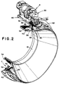
- a fluidic slip ring 60 is connected with the stationary and rotating frame portions.
- the fluidic slip ring includes an outer, stationary annular portion 62 that is mounted to the annular tubular structure and the patient receiving sleeve 10.
- the stationary annular portion has a smooth, flat inner surface.
- the fluidic slip ring also includes a rotatable annular portion 64 which is connected with the rotating bearing race 44 and the rotating frame portion 40.
- the rotating annular portion 64 includes a plurality of channels or grooves, including an incoming cooling fluid channel 66 and an outgoing cooling fluid channel 68.
- a series of seal receiving grooves or channels 70 are disposed between and to either side of the fluid carrying channels 66, 68.
- Gaskets or seals 72 are carried in each groove to isolate the incoming and outgoing cooling fluid and to prevent leakage.
- a pair of leakage channels 74 are disposed outward from the outermost seals to retrieve any fluid that might leak past the fluid seals.
- a pair of final leakage seals 76 are disposed outward from the leakage channels to retain any leaking coolant.
- the stationary annular portion 62 has three fluid paths bored therethrough.
- a first fluid path 80 extends from an inlet connector or coupling 82 to an aperture or port 84 that is in axial alignment with the inlet or chilled cooling fluid channel 66.
- An outlet passage 86 is defined in fluid communication between an outlet coupling or fitting 88 and an aperture or port 90 that is disposed in longitudinal alignment with the outgoing or hot cooling fluid channel 68.
- a drain fitting 92 is connected with a leakage fluid passage 94 that has apertures or ports 96, 98 in alignment with the leakage collecting channels 76.
- the rotating frame has a chilled fluid path 100 extending from the chilled fluid channel 66 to the heat exchanger 32. Heated fluid is returned from the heat exchanger 32 through path 102 to the hot cooling fluid channel 68.
- a circulating means such as a pump 110, pumps cooled cooling fluid from the chiller D to the inlet channel 66, through the heat exchanger 32 to cool the x-ray tube oil and through the return channel 68 into a reservoir 112. Cooling fluid is drawn from the reservoir, through the chiller and returned by the pump 110 through the fluidic slip ring.
- the chiller includes a compressor and freon-type refrigerant system for efficiently cooling the cooling fluid.
- the chiller has an air-fluid heat exchanger that discharges heat at the exterior of the building in which the CT scanner is located.
- the oil-coolant heat exchanger 32 may be eliminated and the x-ray tube oil circulated to the chiller.
Landscapes
- Health & Medical Sciences (AREA)
- Life Sciences & Earth Sciences (AREA)
- Engineering & Computer Science (AREA)
- Medical Informatics (AREA)
- Radiology & Medical Imaging (AREA)
- Biomedical Technology (AREA)
- Biophysics (AREA)
- High Energy & Nuclear Physics (AREA)
- Veterinary Medicine (AREA)
- Nuclear Medicine, Radiotherapy & Molecular Imaging (AREA)
- Optics & Photonics (AREA)
- Pathology (AREA)
- Public Health (AREA)
- Physics & Mathematics (AREA)
- Heart & Thoracic Surgery (AREA)
- Molecular Biology (AREA)
- Surgery (AREA)
- Animal Behavior & Ethology (AREA)
- General Health & Medical Sciences (AREA)
- Pulmonology (AREA)
- Theoretical Computer Science (AREA)
- Computer Networks & Wireless Communication (AREA)
- Apparatus For Radiation Diagnosis (AREA)
- X-Ray Techniques (AREA)
Claims (18)
- Strahlungsgerät, aufweisend eine Strahlenquelle (B), die an einem relativ zu einem stationären Rahmen drehbaren Rahmen (40) angebracht ist,
gekennzeichnet durch
einen Fluid-Gleitring (60), der eine Kühlfluidkommunikation zwischen dem drehbaren Rahmen (40) und dem stationären Rahmen vorsieht, und durch eine Kühlfluidzirkulationseinrichtung (110), die ein Kühlfluid durch den Fluid-Gleitring (60) vom drehbaren Rahmen (40) zum stationären Rahmen (40) und umgekehrt zirkuliert. - Gerät nach Anspruch 1, in welchem die Fluidzirkulationseinrichtung (110) das Kühlfluid zwischen dem drehbaren Rahmen (40) und einer Kühleinrichtung (D) zirkuliert, die am stationären Rahmen zum Kühlen des Kühlfluids angeordnet ist.
- Gerät nach Anspruch 1 oder 2, in welchem die Strahlenquelle (B) ölgekühlt ist und das Gerät ferner einen Wärmeaustauscher (32) zur Übertragung von Wärme vom Strahlenquellen-Kühlöl auf das Kühlfluid umfaßt, wobei der Wärmeaustauscher (32) am drehbaren Rahmen (40) zur Drehung mit der Strahlenquelle (B) angebracht ist.
- Gerät nach einem der Ansprüche 1 bis 3, in welchem der Fluid-Gleitring (60) einen stationären ringförmigen Abschnitt (62) und einen passenden rotierenden ringförmigen Abschnitt (64) aufweist, wobei einer (64) des stationären (62) und rotierenden (64) ringförmigen Abschnitts zumindest zwei Kühlfluid führende Umfangs-Kanäle (66, 68) in sich aufweist, wobei diese Kanäle (66, 68) mit dem anderen solchen ringförmigen Abschnitt (62) zur Beförderung von Kühlfluid zusammenwirken.
- Gerät nach Anspruch 4, in welchem zwei solche Kühlfluid führenden Umfangs-Kanäle (66, 68) vorgesehen sind und das Gerät ferner eine erste ringförmige Dichtung (72), die zwischen den beiden Fluid führenden Kanälen (66, 68) liegt, und zwei weitere ringförmige Dichtungen (72) aufweist, die jeweils auswärts der beiden Kanäle angeordnet sind, derart, daß die Dichtungen (72) verhindern, daß Fluid die beiden Fluid führenden Kanäle (66, 68) verläßt und zwischen den beiden Fluid führenden Kanälen (66, 68) vermischt.
- Gerät nach Anspruch 5, ferner aufweisend ein Paar Umfangs-Abzugskanäle (74), die in einem der ringförmigen Abschnitte (62, 64) jeweils auswärts der weiteren Dichtungen zur Aufnahme von Kühlfluid angeordnet sind, das durch die weiteren Dichtungen (72) geleckt ist, und ein Paar zusätzlicher ringförmiger Dichtungen (76), die jeweils auswärts der Abzugskanäle angeordnet sind.
- Gerät nach Anspruch 6, in welchem der stationäre ringförmige Abschnitt (62) eine sich durch ihn erstreckende Abzugspassage (94) aufweist und Abzugsöffnungen (96, 98) in Fluidkommunikation mit jedem der Abzugskanäle (74) stehen.
- Gerät nach einem der Ansprüche 4 bis 7, in welchem die Fluid führenden Kanäle (66, 68) im rotierenden ringförmigen Abschnitt (64) definiert sind und in welchem der rotierende ringförmige Abschnitt (64) zumindest zwei sich durch ihn erstreckende Fluidpassagen (100, 102) zum Transportieren von Kühlfluid zu Komponenten am rotierbaren Rahmen (40) aufweist.
- Gerät nach einem der Ansprüche 4 bis 7, in welchem der stationäre ringförmige Abschnitt (62) eine glatte Innenfläche aufweist, an die die ringförmigen Dichtungen (72, 76) angreifen.
- Gerät nach einem der Ansprüche 4 bis 9, ferner aufweisend zumindest zwei Fluidpassagen (80, 86) durch den stationären ringförmigen Abschnitt (62), die sich zwischen Einlaß- und Auslaßkühlfluidanschlußteilen (82, 88) und Öffnungen (84, 90) erstrecken, die ausgerichtet mit den Fluid führenden Kanälen (66, 68) vorgesehen sind.
- Gerät nach einem der Ansprüche 1 bis 3 zur Verwendung als Computertomographie-Scanner, in welchem die Strahlenquelle (B) eine Röntgenröhre (B) umfaßt, die am rotierbaren Rahmen (40) zur Drehung um eine durch den stationären Rahmen des Geräts definierte Patientenaufnahmeregion (12) angebracht ist und ein Röntgenstrahlfenser aufweist, durch das Röntgenstrahlen durch die Patientenaufnahmeregion (12) hindurchgelassen werden; und in welchem das Gerät ferner eine Röntgenstrahldetektoreinrichtung (14) zum Detektieren von Röntgenstrahlen umfaßt, die die Patientenaufnahmeregion (12) durchquert haben, und eine Bildrekonstruktionseinrichtung (18) zur Rekonstruktion einer Bilddarstellung aus von der Röntgenstrahldetektoreinrichtung (14) erzeugten Signalen.
- Gerät nach Anspruch 11, in welchem der Fluid-Gleitring (60) umfaßt: einen drehbaren ringförmigen Abschnitt (64), der einen ersten (66) und zweiten (68) Kühlfluidumfangs-Kanal aufweist, die in ihm definiert sind; einen stationären ringförmigen Abschnitt (62), der den drehbaren ringförmigen Abschnitt (64) in einer im wesentlichen angepaßten Beziehung bezüglich der Kanäle (66, 68) umgibt; eine Abdichteinrichtung (72), die das Ausfließen von Kühlfluid aus den Kanälen (66, 68) zwischen dem drehbaren (64) und stationären (62) ringförmigen Abschnitt verhindert; eine erste Fluidpassage (80) durch den stationären ringförmigen Abschnitt (62) mit einer ersten Öffnung (84) in Ausrichtung mit dem ersten Kanal (66) und einer zweiten Passage (86) durch den stationären ringförmigen Abschnitt (62), der eine Öffnung (90) in Ausrichtung mit dem zweiten Kanal (68) aufweist, wobei die Passagen (80, 86) des stationären ringförmigen Abschnitts funktionswirksam mit der Fluidzirkulationseinrichtung (110) verbunden sind, wodurch Kühlfluid durch die erste Passage (80) in den ersten Kanal (66) strömt, vom ersten Kanal (66) zum rotierenden Rahmen (40) strömt, Röntgenröhrenwärme absorbiert, vom rotierenden Rahmen (40) zurück zum zweiten Kanal (68) strömt und durch die zweite Passage (86) des stationären ringförmigen Abschnitts (62) strömt.
- Gerät nach Anspruch 12, ferner aufweisend einen mechanischen Kühler (D), der stationär in Fluidkommunikation mit den Passagen (80, 86) des stationären ringförmigen Abschnitts zum Kühlen des Kühlfluids angebracht ist.
- Gerät nach Anspruch 12 oder 13, in welchem der drehbare ringförmige Abschnitt (64) ein Paar Leckkanäle (74) umfaßt, die jeweils auswärts des ersten bzw. zweiten Kühlfluid (66, 68)-Kanals zur Aufnahme von Kühlfluid angeordnet sind, das durch die Dichtungseinrichtung (72) geleckt ist; eine Leckabdichteinrichtung (76) auswärts der Leckkanäle (74) zum Halten von Leckfluid in den Leckkanälen (74) angeordnet ist; eine dritte Passage (94) durch den stationären ringförmigen Abschnitt (62) definiert ist und Öffnungen (96, 98) ausgerichtet zu jedem der Leckkanäle (74) zum Abziehen von Kühlfluid hieraus aufweist.
- Gerät nach Anspruch 11, in welchem der Fluid-Gleitring (60) umfaßt: einen stationären ringförmigen Abschnitt (62) und einen rotierenden ringförmigen Abschnitt (64), wobei einer (64) des stationären (62) und rotierenden (64) ringförmigen Abschnitts eine Serie von Kanälen (66, 68) in sich aufweist, wobei die Kanäle (66, 68) mit dem anderen ringförmigen Abschnitt (62) zur Definition zumindest zweier Fluid führender Pfade dazwischen zusammenwirken.
- Gerät nach Anspruch 15, ferner aufweisend eine erste ringförmige Dichtung (72), die zwischen den beiden Kanälen (66, 68) angeordnet ist, und zwei weitere ringförmige Dichtungen (72), die jeweils auswärts der beiden Kanäle (66, 68) angeordnet sind, derart, daß die Dichtungen (72) verhindern, daß Fluid aus den beiden Kanälen (66, 68) austritt und sich zwischen den beiden Kanälen (66, 68) vermischt.
- Gerät nach Anspruch 16, ferner aufweisend ringförmige Abzugskanäle (74), die in zumindest einem (64) der ringförmigen Abschnitte (62, 64) auswärts des ersten und zweiten Kanals (66, 68) zur Aufnahme von Kühlfluid angeordnet sind, das durch die Dichtungen (72) geleckt ist, und eine zusätzliche Dichtungseinrichtung (76), die auswärts der Abzugskanäle (74) angeordnet ist.
- Gerät nach Anspruch 17, in welchem der stationäre ringförmige Abschnitt (72) eine glatte Innenseite aufweist, an die die ringförmigen Dichtungen (72) und die Dichtungseinrichtung (76) angreifen.
Applications Claiming Priority (2)
| Application Number | Priority Date | Filing Date | Title |
|---|---|---|---|
| US354384 | 1989-05-19 | ||
| US07/354,384 US5012505A (en) | 1989-05-19 | 1989-05-19 | Fluidic slip ring for CT scanners |
Publications (2)
| Publication Number | Publication Date |
|---|---|
| EP0404335A1 EP0404335A1 (de) | 1990-12-27 |
| EP0404335B1 true EP0404335B1 (de) | 1994-12-07 |
Family
ID=23393089
Family Applications (1)
| Application Number | Title | Priority Date | Filing Date |
|---|---|---|---|
| EP90305268A Expired - Lifetime EP0404335B1 (de) | 1989-05-19 | 1990-05-16 | Strahlungsgerät |
Country Status (4)
| Country | Link |
|---|---|
| US (1) | US5012505A (de) |
| EP (1) | EP0404335B1 (de) |
| JP (1) | JP2893203B2 (de) |
| DE (1) | DE69014729T2 (de) |
Families Citing this family (35)
| Publication number | Priority date | Publication date | Assignee | Title |
|---|---|---|---|---|
| US5299249A (en) * | 1992-11-27 | 1994-03-29 | Picker International, Inc. | Heat transfer techniques for moving thermal energy from high power X-ray tubes on rotating CT gantries to a remote location |
| FR2698721B1 (fr) * | 1992-11-27 | 1995-01-27 | Gen Electric Cgr | Système de refroidissement d'une anode pour tube à rayons X dans un bloc radiogène sans échangeur de chaleur. |
| US5732123A (en) * | 1993-07-13 | 1998-03-24 | David V. Habif, Jr. | Method and system for extending the service life of an x-ray tube |
| US5596622A (en) * | 1993-07-13 | 1997-01-21 | David V. Habif, Jr. | Method and system for extending the service life of an x-ray tube |
| US5440608A (en) * | 1993-07-13 | 1995-08-08 | David V. Habif, Jr. | Method and system for extending the service life of an x-ray tube |
| US5610968A (en) * | 1995-03-17 | 1997-03-11 | Picker International, Inc. | High capacity cooling system for CT gantry |
| US5978438A (en) * | 1997-12-12 | 1999-11-02 | Picker International, Inc. | Wideband non-contact data link using X-ray sources to excite scintillating material receiving device |
| US6254272B1 (en) | 1999-02-05 | 2001-07-03 | Maurice D. Dilick | Method and apparatus for extending the life of an x-ray tube |
| DE19945418C1 (de) * | 1999-09-22 | 2001-04-26 | Siemens Ag | Kühleinrichtung und Computertomograph mit einer Kühleinrichtung |
| DE19945413B4 (de) | 1999-09-22 | 2006-04-13 | Siemens Ag | Kühleinrichtung und Computertomograph mit einer Kühleinrichtung |
| US6327327B1 (en) | 1999-09-27 | 2001-12-04 | Picker International, Inc. | Multi-channel segmented slip ring |
| US6276145B1 (en) * | 1999-10-27 | 2001-08-21 | Picker International, Inc. | Aerostatic CT suspension |
| US6452998B2 (en) | 2000-07-31 | 2002-09-17 | Analogic Corporation | Tiltable gantry for x-ray tomography system |
| US6337894B1 (en) | 2000-09-20 | 2002-01-08 | Analogic Corporation | Rotary bearing assembly for CT scanner gantry |
| US6511224B1 (en) * | 2000-10-18 | 2003-01-28 | Koninklijke Philips Electronics, N.V. | Heat removal from high power CT x-ray tubes using heat buffer and refrigeration techniques |
| US6457859B1 (en) | 2000-10-18 | 2002-10-01 | Koninklijke Philips Electronics Nv | Integration of cooling jacket and flow baffles on metal frame inserts of x-ray tubes |
| US6404845B1 (en) | 2001-05-09 | 2002-06-11 | Philips Medical Systems (Cleveland), Inc. | Aerostatic rotor bearing |
| US7273479B2 (en) * | 2003-01-15 | 2007-09-25 | Cryodynamics, Llc | Methods and systems for cryogenic cooling |
| US7410484B2 (en) * | 2003-01-15 | 2008-08-12 | Cryodynamics, Llc | Cryotherapy probe |
| US7083612B2 (en) * | 2003-01-15 | 2006-08-01 | Cryodynamics, Llc | Cryotherapy system |
| DE10312253B4 (de) * | 2003-03-19 | 2007-04-05 | Siemens Ag | Kühlsystem, Computertomographie-Anlage mit einem solchen Kühlsystem und Verfahren zur Kühlung einer Gantry |
| US20050117706A1 (en) * | 2003-12-01 | 2005-06-02 | Powell David L. | Cooling and power system for a medical imaging system |
| JP2007534413A (ja) * | 2004-04-27 | 2007-11-29 | コーニンクレッカ フィリップス エレクトロニクス エヌ ヴィ | 開放アクセス空気軸受ガントリ |
| CN101605497B (zh) * | 2007-02-13 | 2012-09-05 | 皇家飞利浦电子股份有限公司 | 一种具有冷却装置的医学诊断x射线设备 |
| EP2111162B1 (de) * | 2007-02-13 | 2018-11-14 | Koninklijke Philips N.V. | Röntgengerät für medizinische diagnosen mit kühlvorrichtung |
| MY154880A (en) * | 2007-06-26 | 2015-08-14 | Filligent Ltd | Devices and methods for decreasing human pathogen transmission |
| KR102300577B1 (ko) | 2013-09-24 | 2021-09-08 | 아다지오 메디컬, 인크. | 혈관내 근임계 유체 기반 냉동절제 카테터 및 관련 방법 |
| EP3131487A4 (de) | 2014-04-17 | 2017-12-13 | Adagio Medical, Inc. | Auf nahkritischer flüssigkeit basierender endovaskulärer kryoablationskatheter mit mehreren vorgeformten behandlungsformen |
| KR101994471B1 (ko) | 2014-11-13 | 2019-06-28 | 아다지오 메디컬, 인크. | 압력 변조 냉동절제 시스템 및 관련 방법 |
| US11051867B2 (en) | 2015-09-18 | 2021-07-06 | Adagio Medical, Inc. | Tissue contact verification system |
| US10864031B2 (en) | 2015-11-30 | 2020-12-15 | Adagio Medical, Inc. | Ablation method for creating elongate continuous lesions enclosing multiple vessel entries |
| WO2017220116A1 (en) * | 2016-06-20 | 2017-12-28 | Schleifring Und Apparatebau Gmbh | Cooling device for ct scanner or radiotherapy devices |
| EP3678567B1 (de) | 2017-09-05 | 2025-09-17 | Adagio Medical, Inc. | Ablationskatheter mit einem formgedächtnismandrin |
| BR112020013967A2 (pt) | 2018-01-10 | 2020-12-01 | Adagio Medical, Inc. | elemento de crioablação com forro condutivo |
| WO2022019954A1 (en) * | 2020-07-20 | 2022-01-27 | Siemens Medical Solutions Usa, Inc. | Cooling system with solid material heatsink for a diagnostic medical imaging apparatus |
Family Cites Families (7)
| Publication number | Priority date | Publication date | Assignee | Title |
|---|---|---|---|---|
| GB1527813A (en) * | 1976-06-02 | 1978-10-11 | Emi Ltd | Cooling x-ray apparatus |
| GB2026812A (en) * | 1978-07-28 | 1980-02-06 | Emi Ltd | Power supply arrangement for computerised tomographic apparatus |
| US4644573A (en) * | 1979-09-17 | 1987-02-17 | Picker Corporation | Computed tomography method and apparatus |
| US4651338A (en) * | 1984-10-08 | 1987-03-17 | Siemens Aktiengesellschaft | Cooling system for a tomograph apparatus |
| US4709559A (en) * | 1985-08-01 | 1987-12-01 | Siemens Aktiengesellschaft | Cooling system for relatively movable components |
| US4853946A (en) * | 1986-11-14 | 1989-08-01 | Picker International, Inc. | Diagonostic service system for CT scanners |
| US4866743A (en) * | 1987-04-29 | 1989-09-12 | Siemens Aktiengesellschaft | Computer tomography apparatus with a closed circulation cooling system |
-
1989
- 1989-05-19 US US07/354,384 patent/US5012505A/en not_active Expired - Lifetime
-
1990
- 1990-05-16 DE DE69014729T patent/DE69014729T2/de not_active Expired - Fee Related
- 1990-05-16 EP EP90305268A patent/EP0404335B1/de not_active Expired - Lifetime
- 1990-05-17 JP JP2125623A patent/JP2893203B2/ja not_active Expired - Fee Related
Also Published As
| Publication number | Publication date |
|---|---|
| DE69014729T2 (de) | 1995-04-27 |
| EP0404335A1 (de) | 1990-12-27 |
| US5012505A (en) | 1991-04-30 |
| JPH0380837A (ja) | 1991-04-05 |
| JP2893203B2 (ja) | 1999-05-17 |
| DE69014729D1 (de) | 1995-01-19 |
Similar Documents
| Publication | Publication Date | Title |
|---|---|---|
| US5012505A (en) | Fluidic slip ring for CT scanners | |
| US5610968A (en) | High capacity cooling system for CT gantry | |
| JP5265906B2 (ja) | 対流冷却式x線管ターゲット及びその製造方法 | |
| US5299249A (en) | Heat transfer techniques for moving thermal energy from high power X-ray tubes on rotating CT gantries to a remote location | |
| JP4141833B2 (ja) | X線管の金属フレームインサートへの冷却ジャケット及び流れバッフルの一体化 | |
| JPH0413588Y2 (de) | ||
| US6074092A (en) | Cooling system for an x-ray source | |
| US6412979B1 (en) | Computed tomography system with arrangement for cooling the x-ray radiator mounted on a rotating gantry | |
| JP5775257B2 (ja) | 液体潤滑式軸受及び液体冷却式陽極ターゲット組立体を持つx線管 | |
| EP1537825B1 (de) | Kühl- und Leistungssystem für eine medizinische Abbildungsanordnung | |
| US6709156B1 (en) | Cooling device and computed tomography apparatus employing same | |
| US7197115B2 (en) | Cantilever and straddle x-ray tube configurations for a rotating anode with vacuum transition chambers | |
| US7236571B1 (en) | Systems and apparatus for integrated X-Ray tube cooling | |
| JP4746335B2 (ja) | 電子回収器システム | |
| US20060050852A1 (en) | Integrated fluid pump for use in an x-ray tube | |
| JP5902054B2 (ja) | X線コンピュータ断層撮影装置 | |
| US7113568B2 (en) | Liquid cooled bearing housing with greased lubricated rotating anode bearings for an x-ray tube | |
| CN104274197B (zh) | 一种冷却系统及设备 | |
| JP2020013715A (ja) | X線管装置及びx線コンピュータ断層撮影装置 | |
| US12597580B2 (en) | X-ray generating apparatus and imaging device | |
| WO2004062049A2 (en) | X-ray housing window | |
| EP4447618A1 (de) | Röntgenröhrenvorrichtung und röntgen-ct-gerät | |
| JPH0810248A (ja) | X線ct装置 | |
| JP2001276052A (ja) | カソードスキャン型x線発生器及びx線ctスキャナ | |
| JP2010104819A (ja) | X線コンピュータ断層撮影装置及びx線管装置 |
Legal Events
| Date | Code | Title | Description |
|---|---|---|---|
| PUAI | Public reference made under article 153(3) epc to a published international application that has entered the european phase |
Free format text: ORIGINAL CODE: 0009012 |
|
| AK | Designated contracting states |
Kind code of ref document: A1 Designated state(s): DE FR GB NL |
|
| 17P | Request for examination filed |
Effective date: 19901127 |
|
| 17Q | First examination report despatched |
Effective date: 19930408 |
|
| GRAA | (expected) grant |
Free format text: ORIGINAL CODE: 0009210 |
|
| AK | Designated contracting states |
Kind code of ref document: B1 Designated state(s): DE FR GB NL |
|
| PG25 | Lapsed in a contracting state [announced via postgrant information from national office to epo] |
Ref country code: NL Effective date: 19941207 |
|
| ET | Fr: translation filed | ||
| REF | Corresponds to: |
Ref document number: 69014729 Country of ref document: DE Date of ref document: 19950119 |
|
| NLV1 | Nl: lapsed or annulled due to failure to fulfill the requirements of art. 29p and 29m of the patents act | ||
| PG25 | Lapsed in a contracting state [announced via postgrant information from national office to epo] |
Ref country code: GB Effective date: 19950516 |
|
| PLBE | No opposition filed within time limit |
Free format text: ORIGINAL CODE: 0009261 |
|
| STAA | Information on the status of an ep patent application or granted ep patent |
Free format text: STATUS: NO OPPOSITION FILED WITHIN TIME LIMIT |
|
| 26N | No opposition filed | ||
| GBPC | Gb: european patent ceased through non-payment of renewal fee |
Effective date: 19950516 |
|
| REG | Reference to a national code |
Ref country code: FR Ref legal event code: CD |
|
| PGFP | Annual fee paid to national office [announced via postgrant information from national office to epo] |
Ref country code: FR Payment date: 20040527 Year of fee payment: 15 |
|
| PGFP | Annual fee paid to national office [announced via postgrant information from national office to epo] |
Ref country code: DE Payment date: 20040714 Year of fee payment: 15 |
|
| REG | Reference to a national code |
Ref country code: FR Ref legal event code: TP |
|
| PG25 | Lapsed in a contracting state [announced via postgrant information from national office to epo] |
Ref country code: DE Free format text: LAPSE BECAUSE OF NON-PAYMENT OF DUE FEES Effective date: 20051201 |
|
| PG25 | Lapsed in a contracting state [announced via postgrant information from national office to epo] |
Ref country code: FR Free format text: LAPSE BECAUSE OF NON-PAYMENT OF DUE FEES Effective date: 20060131 |
|
| REG | Reference to a national code |
Ref country code: FR Ref legal event code: ST Effective date: 20060131 |