EP0404363A2 - Dispositifs de bobinage - Google Patents
Dispositifs de bobinage Download PDFInfo
- Publication number
- EP0404363A2 EP0404363A2 EP90305781A EP90305781A EP0404363A2 EP 0404363 A2 EP0404363 A2 EP 0404363A2 EP 90305781 A EP90305781 A EP 90305781A EP 90305781 A EP90305781 A EP 90305781A EP 0404363 A2 EP0404363 A2 EP 0404363A2
- Authority
- EP
- European Patent Office
- Prior art keywords
- shaft
- deflecting member
- fingers
- winding device
- actuating rod
- Prior art date
- Legal status (The legal status is an assumption and is not a legal conclusion. Google has not performed a legal analysis and makes no representation as to the accuracy of the status listed.)
- Withdrawn
Links
Images


Classifications
-
- B—PERFORMING OPERATIONS; TRANSPORTING
- B65—CONVEYING; PACKING; STORING; HANDLING THIN OR FILAMENTARY MATERIAL
- B65H—HANDLING THIN OR FILAMENTARY MATERIAL, e.g. SHEETS, WEBS, CABLES
- B65H54/00—Winding, coiling, or depositing filamentary material
- B65H54/02—Winding and traversing material on to reels, bobbins, tubes, or like package cores or formers
- B65H54/40—Arrangements for rotating packages
- B65H54/54—Arrangements for supporting cores or formers at winding stations; Securing cores or formers to driving members
- B65H54/543—Securing cores or holders to supporting or driving members, e.g. collapsible mandrels
-
- B—PERFORMING OPERATIONS; TRANSPORTING
- B65—CONVEYING; PACKING; STORING; HANDLING THIN OR FILAMENTARY MATERIAL
- B65H—HANDLING THIN OR FILAMENTARY MATERIAL, e.g. SHEETS, WEBS, CABLES
- B65H2701/00—Handled material; Storage means
- B65H2701/30—Handled filamentary material
- B65H2701/31—Textiles threads or artificial strands of filaments
Definitions
- This invention relates to winding devices of the type wherein a strand material is wound on to a bobbin tube which is mounted on a rotatable spindle.
- the invention relates to high speed textile filament winding devices, and to means whereby a bobbin tube, on which a textile filament is to be wound, is secured on the rotatable spindle of a high speed winding machine.
- Bobbin securing devices of various types are known.
- four independent arms are located in slots in supporting sleeves, and have chamferred ends to co-operate with a conical, axially movably bush.
- the arms pivot about their other ends as the chamferred ends slide up the conical surface of the bush to move radially outwardly and grip the internal surface of the bobbin tube.
- the arms are retained in the slots by a circumferentially extending spring.
- Such an arrangement is complicated to manufacture and assemble.
- the bobbin tube is contacted only on a small surface area of the top edges of the arms so that a large torque loading on acceleration or stopping of a heavy package cannot be transmitted without risk of damage to the internal surface of the bobbin tube by the arms.
- the invention provides a winding device comprising a rotatable shaft, at least one bobbin tube gripping element mounted on the shaft to rotate therewith and a respective deflecting member also mounted on the shaft,at least one of the or each element and respective deflecting member being movable axially of the shaft, wherein the or each element comprises a sleeve part having a plurality of resilient fingers extending in an axial direction therefrom, and the deflecting member and the fingers have co-operating surfaces whereby the fingers are deflected radially of the shaft on relative axial movement between the deflecting member and the element.
- the fingers may be formed by a plurality of slots in the element extending axially from one end thereof to the sleeve part.
- the element may be formed of a plastics material.
- the co-operating surfaces may be of substantially conical form.
- the deflecting member may comprise an annular ring which may be slidably located on the shaft to effect the relative movement.
- the shaft may be hollow, and the winding device may comprise an actuating rod extending within the hollow shaft.
- the winding device may also comprise an end cap secured to the actuating rod and located at a free end of the shaft to be movable with the actuating rod axially of the shaft.
- the winding device may comprise a plurality of bobbin tube gripping elements spaced longitudinally of the shaft, and for each element a respective deflecting member. Movement of the actuating rod and end cap may cause each deflecting member and respective element to transmit an actuating force to the next successive deflecting member and respective element to cause relative movement therebetween and consequential radial deflection of the fingers of each element. Alternatively one of each element and its respective deflecting member may be secured to the shaft and the other connected to the actuating rod whereby movement of the actuating rod causes the relative movement and consequential radial deflection of the fingers of each element.
- the actuating rod may be connected to an element or a deflecting member by means of a radially extending spigot which passes through an axially extending slot in the shaft.
- the winding device may comprise spring means operable to move the actuating rod in a direction to cause the radially outward deflection of the fingers to grip a bobbin tube when mounted on the winding device.
- the winding device may also comprise actuating means operable to move the actuating rod in the opposite direction to allow radially inward deflection of the fingers to release a bobbin tube when mounted on the winding device.
- the actuating means may be fluid, for example pneumatic, actuating means.
- the winding device may also comprise driving means for the shaft, and may also comprise braking means for the shaft.
- the actuating means, the driving means and the braking means may be located at a drive end of the shaft which is mounted in a machine frame of a winding mechanism.
- the winding mechanism may comprise a turret mounted on the machine frame for rotation relative thereto, and two of the winding devices mounted in the turret.
- the shafts of the two winding devices may be diametrically opposed and substantially equidistant from the axis of rotation of the turret, and the axes of the shafts may be substantially parallel with that axis of rotation.
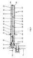
- a winding mechanism denoted generally by the numeral 10, comprising a machine frame 11 on which is mounted a turret 12 for rotation relative to the frame 11 about a horizontal axis 13.
- the two winding devices 14 are diametrically opposed and equidistant from the turret axis 13, and have axis 15 substantially parallel with the turret axis 13.
- the winding devices 14 move between a winding location and a service location.
- With a winding device bobbin tubes 16 mounted on the winding device 14. With the winding device 14 in the service location full packages may be doffed from the winding device 14 and new bobbin tubes 16 placed thereon.
- the winding device 14 comprises a hollow tubular shaft 17 having one end mounted in bearings 18 in the turret 12 so as to be rotatable about the shaft axis 15.
- a pulley 19 receives a drive belt therearound to drive the shaft 17 and a brake device 21 is provided to stop the shaft 17 when required for doffing full packages and donning new bobbin tubes 16.
- An actuating rod 22 extends within the hollow shaft 17 for sliding movement along the axis 15, and is resiliently biassed towards the turret 12 and machine frame 11 by means of a compression spring 23.
- a pneumatic actuator 24 is operable to move the actuating rod 22 in the opposite direction.
- Spaced slide discs 25 assist in locating the actuating rod 22 for its sliding movement axially within the hollow shaft 17.
- An end cap 26 is secured to the free end of the actuating rod 22 to move therewith.
- the winding device 10 may be adapted for receiving one or more than two bobbin tubes 16 on each shaft 17 if desired, the appropriate number of bobbin tube gripping arrangements as hereinafter described being provided.
- each bobbin tube 16 the gripping arrangement comprises two bobbin tube gripping elements 27 and respective deflecting members 28.
- Each deflecting member 28 comprises an annular ring having an outer conical surface 29 at the end thereof adjacent the respective gripping element 27.
- Each bobbin tube gripping element 27 comprises a sleeve part 30 and a plurality of resilient fingers 31 extending axially therefrom.
- the fingers 31 are formed by a plurality of radial slots 32 provided in the element 27 extending from one end thereof to the sleeve part 30.
- the fingers 31 are provided with an internal conical surface 33 to co-operate with the conical outer surface 29 of the respective deflecting member 28.
- Both the deflecting members 28 and the elements 27 are slidably mounted on the hollow shaft 17. Spacers 34, also slidably mounted on the shaft 17, ensure transmission of axial forces between successive element and deflecting member assemblies 27, 28.
- Operation of the pneumatic actuator 24 moves the actuating rod 15 and end cap 26 in the opposite direction, against the force of the spring 23, to release the gripping forces on the bobbin tubes 16 for doffing and donning purposes.
- the bobbin tube gripping elements 27 are of a plastics material for simple and inexpensive manufacture.
- the embodiment described above also provides for simple and inexpensive manufacture, there being no pneumatic apparatus in the hollow shaft 17 requiring a bore of accurate tolerance, and no slots for actuating mechanisms are required in the shaft 17 surface.
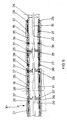
- the gripping force on the bobbin tube near to the turret 12 may be less than that near to the end cap 26, and the former may be inadequate. If that is the case an alternative embodiment as shown in Fig 5 may be used.
- each deflecting member 28 and its respective gripping element 27 operates independently of the other deflecting members 28 and their respective gripping elements 27.
- the lower part of Fig 5 shows the winding device 10 in the bobbin tube release position, eg for donning or doffing purposes, whilst the upper part of Fig 5 shows the winding device 10 in the bobbin tube gripping position, eg during package winding.
- the deflecting member 28 adjacent the end cap 26 is slidably mounted on the shaft 17. However its respective gripping element 27 is prevented from sliding axially of the shaft 17 by means of an element retaining sleeve 35 which is immovably located on the shaft 17 by retaining pins 36. In consequence movement of the actuating rod 22 axially of the shaft 17 causes relative movement between the deflecting member 28 and the gripping element 27 to grip or release the bobbin tube 16 as previously described.
- the deflecting member 281 is immovably located on the shaft 17 by means of retaining pins 36.
- the element retaining sleeve 351 is connected to the actuating rod 22 by means of connecting pins 37, each extending through a slot 38 in the shaft 17, and slide disc 25.
- movement of the actuating rod 22 axially of the shaft 17 causes the element retaining sleeve 351 and the gripping element 271 to slide axially of the shaft 17 and relative to the deflecting member 28 to grip or release the bobbin tube 16.
- the next gripping element 2711 is immovably located on the shaft 17 by means of immovably mounted element retaining sleeve 3511 whilst the deflecting member 2811 is movable with the actuating rod 22.
- the last gripping element 27111 is movable with the actuating rod 22, and its element retaining sleeve 35111 is immovably located on the shaft 17, either by means of retaining pins 36 or by abutting the bearing 18 in the turret 12 or a step on the shaft 17.
- the gripping elements 27 are preferably made of a plastics material, other materials may be used if required in certain cases, for example steel may be used provided that the cross-sectional dimensions of the fingers 31, at least in the region adjacent the sleeve part 30, are such that the fingers 31 are resiliently deflectable radially outwardly.
Landscapes
- Winding Filamentary Materials (AREA)
- Replacing, Conveying, And Pick-Finding For Filamentary Materials (AREA)
- Storage Of Web-Like Or Filamentary Materials (AREA)
Applications Claiming Priority (2)
| Application Number | Priority Date | Filing Date | Title |
|---|---|---|---|
| GB898914281A GB8914281D0 (en) | 1989-06-21 | 1989-06-21 | Winding devices |
| GB8914281 | 1989-06-21 |
Publications (2)
| Publication Number | Publication Date |
|---|---|
| EP0404363A2 true EP0404363A2 (fr) | 1990-12-27 |
| EP0404363A3 EP0404363A3 (fr) | 1991-12-18 |
Family
ID=10658837
Family Applications (1)
| Application Number | Title | Priority Date | Filing Date |
|---|---|---|---|
| EP19900305781 Withdrawn EP0404363A3 (fr) | 1989-06-21 | 1990-05-29 | Dispositifs de bobinage |
Country Status (3)
| Country | Link |
|---|---|
| EP (1) | EP0404363A3 (fr) |
| JP (1) | JPH0342470A (fr) |
| GB (2) | GB8914281D0 (fr) |
Cited By (1)
| Publication number | Priority date | Publication date | Assignee | Title |
|---|---|---|---|---|
| EP0663365A4 (fr) * | 1993-07-14 | 1995-11-02 | Toray Industries | Support de bobine et mecanisme de rembobinage comportant un tel support. |
Families Citing this family (1)
| Publication number | Priority date | Publication date | Assignee | Title |
|---|---|---|---|---|
| JP6547964B2 (ja) * | 2016-06-17 | 2019-07-24 | 株式会社豊田自動織機 | ラップ巻取り装置 |
Family Cites Families (7)
| Publication number | Priority date | Publication date | Assignee | Title |
|---|---|---|---|---|
| BE526760A (fr) * | 1953-04-29 | |||
| CH443994A (de) * | 1966-12-13 | 1968-02-15 | Rieter Ag Maschf | Hülsenspannvorrichtung |
| US3448937A (en) * | 1967-01-04 | 1969-06-10 | Synchro Machine Co | Expanding arbor for wire spooling machine |
| US4232835A (en) * | 1979-07-12 | 1980-11-11 | E. I. Du Pont De Nemours And Company | Bobbin chuck |
| US4241883A (en) * | 1979-08-24 | 1980-12-30 | E. I. Du Pont De Nemours And Company | Manually operated bobbin chuck |
| DD153487A3 (de) * | 1980-02-21 | 1982-01-13 | Lutz Brenner | Huelsenspannvorrichtung fuer mehrfach-spulentraeger |
| US4359194A (en) * | 1980-03-24 | 1982-11-16 | Plastech Inc. | Two piece mandril for quick mounting and release of cones, used in textile industry |
-
1989
- 1989-06-21 GB GB898914281A patent/GB8914281D0/en active Pending
-
1990
- 1990-05-29 EP EP19900305781 patent/EP0404363A3/fr not_active Withdrawn
- 1990-05-29 GB GB9011959A patent/GB2233356A/en not_active Withdrawn
- 1990-06-14 JP JP15658490A patent/JPH0342470A/ja active Pending
Cited By (2)
| Publication number | Priority date | Publication date | Assignee | Title |
|---|---|---|---|---|
| EP0663365A4 (fr) * | 1993-07-14 | 1995-11-02 | Toray Industries | Support de bobine et mecanisme de rembobinage comportant un tel support. |
| EP0850867A3 (fr) * | 1993-07-14 | 1998-07-22 | Toray Industries, Inc. | Support de bobine et mécanisme de rembobinage comportant un tel support |
Also Published As
| Publication number | Publication date |
|---|---|
| EP0404363A3 (fr) | 1991-12-18 |
| GB2233356A (en) | 1991-01-09 |
| JPH0342470A (ja) | 1991-02-22 |
| GB9011959D0 (en) | 1990-07-18 |
| GB8914281D0 (en) | 1989-08-09 |
Similar Documents
| Publication | Publication Date | Title |
|---|---|---|
| KR900008533B1 (ko) | 조방기(roving frame) 튜우브 자동교체용 장치를 위한 튜우브나 그 유사체의 그립장치 | |
| US3815836A (en) | Sleeve chuck for thread winding device | |
| US4429838A (en) | Clamping chuck in winding machines | |
| US3637156A (en) | Expansible mandrel | |
| EP0404363A2 (fr) | Dispositifs de bobinage | |
| US4014476A (en) | Apparatus for winding continuous threads or yarns | |
| US3593934A (en) | High speed bobbin chuck | |
| US4777792A (en) | Gripping device for tubes or the like, for apparatus for automatically replacing these in textile machines | |
| US4938017A (en) | Apparatus for automatic doffing and donning of tubes in a textile spinning or twisting machine | |
| US4101085A (en) | Radially expansible collet for a tubular sleeve | |
| US3526369A (en) | Chuck spindle | |
| MX2014009555A (es) | Soporte de eje con nucleo de carton para paquetes de hilo. | |
| US4241883A (en) | Manually operated bobbin chuck | |
| US3833179A (en) | Mandrel | |
| US4765562A (en) | Device for positioning and holding a yarn support tube during an operation of unwinding or winding | |
| US3335971A (en) | Yarn tube driving means | |
| US3946958A (en) | Rotatable yarn winding spindle | |
| US3430892A (en) | Creel adapter for filamentary material processing apparatus | |
| US3112082A (en) | Windup chuck | |
| EP0744370A1 (fr) | Dispositif de support de bobine | |
| JP3431664B2 (ja) | 糸巻回装置 | |
| CN110356928A (zh) | 一种适用于圆柱纱筒和圆锥纱筒的抓取装置 | |
| US3471095A (en) | Windup chuck | |
| NL7907514A (nl) | Opwikkelspil. | |
| EP0219752B1 (fr) | Machine motrice |
Legal Events
| Date | Code | Title | Description |
|---|---|---|---|
| PUAI | Public reference made under article 153(3) epc to a published international application that has entered the european phase |
Free format text: ORIGINAL CODE: 0009012 |
|
| AK | Designated contracting states |
Kind code of ref document: A2 Designated state(s): CH DE FR IT LI |
|
| PUAL | Search report despatched |
Free format text: ORIGINAL CODE: 0009013 |
|
| AK | Designated contracting states |
Kind code of ref document: A3 Designated state(s): CH DE FR IT LI |
|
| STAA | Information on the status of an ep patent application or granted ep patent |
Free format text: STATUS: THE APPLICATION IS DEEMED TO BE WITHDRAWN |
|
| 18D | Application deemed to be withdrawn |
Effective date: 19920619 |