EP0404965A1 - Dispositif d'entrainement variable de soupapes - Google Patents
Dispositif d'entrainement variable de soupapes Download PDFInfo
- Publication number
- EP0404965A1 EP0404965A1 EP90901029A EP90901029A EP0404965A1 EP 0404965 A1 EP0404965 A1 EP 0404965A1 EP 90901029 A EP90901029 A EP 90901029A EP 90901029 A EP90901029 A EP 90901029A EP 0404965 A1 EP0404965 A1 EP 0404965A1
- Authority
- EP
- European Patent Office
- Prior art keywords
- magnetic poles
- valve
- intake
- tooth
- fixed magnetic
- Prior art date
- Legal status (The legal status is an assumption and is not a legal conclusion. Google has not performed a legal analysis and makes no representation as to the accuracy of the status listed.)
- Granted
Links
Images

Classifications
-
- H—ELECTRICITY
- H02—GENERATION; CONVERSION OR DISTRIBUTION OF ELECTRIC POWER
- H02K—DYNAMO-ELECTRIC MACHINES
- H02K41/00—Propulsion systems in which a rigid body is moved along a path due to dynamo-electric interaction between the body and a magnetic field travelling along the path
- H02K41/02—Linear motors; Sectional motors
- H02K41/03—Synchronous motors; Motors moving step by step; Reluctance motors
- H02K41/031—Synchronous motors; Motors moving step by step; Reluctance motors of the permanent magnet type
-
- F—MECHANICAL ENGINEERING; LIGHTING; HEATING; WEAPONS; BLASTING
- F01—MACHINES OR ENGINES IN GENERAL; ENGINE PLANTS IN GENERAL; STEAM ENGINES
- F01L—CYCLICALLY OPERATING VALVES FOR MACHINES OR ENGINES
- F01L9/00—Valve-gear or valve arrangements actuated non-mechanically
- F01L9/20—Valve-gear or valve arrangements actuated non-mechanically by electric means
Definitions
- the present invention relates to a system for actuating intake and exhaust valves in stepped movement with a linear stepping motor disposed on a stem end of the intake and exhaust valves of an engine.
- Some conventional actuating systems for opening and closing intake and exhaust valves include a single camshaft which has cams for the intake and exhaust valves, the camshaft being disposed above or laterally of an engine.
- the camshaft is operatively connected to the crankshaft of the engine by a rotation transmitting means such as a belt, so that the camshaft can rotate synchronously with the rotation of the engine.
- the valves have stems whose ends are pressed by cam surfaces of the camshaft through a link mechanism such as rocker arms or push rods.
- the intake and exhaust valves are normally closed by springs, and can be opened when their stem ends are pressed by the cam surfaces.
- an intake camshaft having cams for acting on intake valves and an exhaust camshaft having cams for acting on exhaust valves are disposed above an engine.
- the intake and exhaust valves are opened when the stem ends of the intake valves are directly pushed by the cam surfaces of the intake camshaft and the stem ends of the exhaust valves are directly pushed by the cam surfaces of the exhaust camshaft.
- the above conventional actuating systems for opening and closing intake and exhaust valves include camshafts and link mechanisms added to the engine, which is thus necessarily large in size.
- valve opening and closing timing is preset such that the engine operates with high efficiency when it rotates at a predetermined speed. Therefore, the engine output power and efficiency are lower when the engine rotates at a speed different from the predetermined speed.
- valve actuating systems for opening and closing intake and exhaust valves under electromagnetic forces from electromagnets, rather than with camshafts, as disclosed in Japanese Laid-Open Patent Publications Nos. 58-183805 and 61-76713.
- the distance between the electromagnet and the magnetic body varies when the intake and exhaust valves are actuated, resulting in an abrupt change in electromagnetic forces and highly unstable operation of the intake and exhaust valves.
- a system for actuating intake and exhaust valves of an engine in stepped movement comprising a magnetic body coupled to a valve, the magnetic body being reciprocally movable and having a plurality of tooth-like magnetic poles juxtaposed at equal intervals in the direction in which the magnetic body is reciprocally movable, a plurality of fixed magnetic poles disposed in confronting relation to the tooth-like magnetic poles, the fixed magnetic poles being spaced at intervals different from the intervals of the tooth-like magnetic poles in the direction in which the tooth-like magnetic poles are juxtaposed, excitation coils wound respectively around the fixed magnetic poles, for generating magnetic lines of force through'the fixed magnetic poles, and magnetic-line-of-force control means for controlling the energization of the coils to produce combined electromagnetic forces acting between the tooth-like magnetic poles and the fixed magnetic poles in an opening direction, for driving the magnetic body.
- the intake/exhaust valve is opened and closed under attractive and repelling forces acting between the tooth-like magnetic poles juxtaposed on the magnetic body coupled to the intake/exhaust valve and the fixed magnetic poles confronting the tooth-like magnetic poles. Since opening and closing forces acting on the intake/exhaust valve remain unchanged irrespective of movement of the intake/exhaust valve, stable opening and closing forces are applied to the intake/exhaust valve.
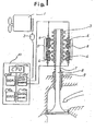
- Fig. 1 is a block diagram showing an actuating system according to an embodiment of the present invention
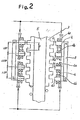
- F ig. 2 is an enlarged view of the stem end of an intake valve.
- An engine 1 has an output shaft, adjacent to which there is disposed a rotation sensor 2 for detecting the rotational speed and phase of the output shaft and converting the detected speed and phase into a signal.
- the engine 1 has intake and exhaust ports which are opened and closed by intake and exhaust valves, respectively. Of these intake and exhaust valves, the intake valve will mainly be described below.
- An intake valve 8 is made of a highly strong and lightweight material such as ceramic.
- the intake valve 8 has a stem axially slidably supported by a valve guide 9 .
- a valve seat 11 is mounted in the intake port of an intake passage. The intake port is closed when the head of the intake valve 8 is closely held against the valve seat 11.
- the stem end of the intake valve 8 is fitted in a scale 3 which is made of a magnetic material and having teeth on its peripheral surface at a pitch P, the teeth . serving as magnetic poles.
- left and right upper electromagnets 4 each having fixed magnetic poles 4 c, 4 d spaced from each other by a distance of 1. 5 ' P
- left and right lower electromagnets 6 each having fixed magnetic poles 6 c, 6d spaced from each other at a distance of 1.5 P
- the upper and lower electromagnets 4, 6 being spaced from each other by a distance of 1.75 P.
- the upper and lower electromagnets 4, 6 are joined to each other by permanent magnets 5.
- Coils 4 a, 4b, 6a, 6b are disposed respectively around the fixed magnetic poles 4 c, 4d, 6 c, 6d.
- the coils on the fixed magnetic poles 4c, 4 d and the coils on the fixed magnetic poles 6c, 6d are respectively connected in series with each other.
- the upper electromagnets 4 on the lefthand and righthand sides of the intake valve 8 are connected such that they are supplied with the same electric power signal, and the left and right lower electromagnets 6 are also connected such that they are supplied with the same electric power signal.
- a spring 7 is disposed between the slider 3 and the valve guide 9 for preventing the intake valve 8 from dropping when the electromagnets are de-energized.
- wires for supplying the electric power signals to the upper and lower electromagnets 4, 6 are connected to an input/output interface 10d in a control unit 10.
- the rotation sensor 2 is also connected to the input/output interface 10d.
- the control unit 10 includes, in addition to the input/output interface 10d, a RAM 10c'for temporarily storing data and the results of arithmetic operations, a ROM 10b for storing a program and various relation maps, a CPU 10a for effective arithmetic operations according to the program stored in the ROM lOb, and a control memory 10e for controlling the flow of signals in the control unit 10.
- Figs. 3(a) through 3(e) show the conditions of magnetic lines of force at the stem end of the intake valve 8.
- Figs. 3(a) through 3(e) illustrate the righthand portion of the intake valve 8. Those of the coils 4a, 4b, 6a, 6b which are energized are indicated by the solid lines, and those which are de-energized are indicated by the broken lines.
- the upper electromagnet 4 is energized in a direction to produce an N pole on the tip of the fixed magnetic pole 4 c.
- the coils 4a, 4b of the upper electromagnet 4 are connected in series to each other. Since, however, the magnetic lines of force generated by the fixed magnetic poles 4c, 4d are oriented in opposite directions upon energization of the upper electromagnet 4, the magnetic lines of force generated by the coil 4b cancel out the magnetic lines of force generated oy the permanent magnet 5 , and no pole is produced on the tip of the fixed magnetic pole 4d.
- the magnetic lines of force generated by the coil 4a are in the same direction as the magnetic lines of force generated by the permanent magnet 5, so that an N pole is produced on the tip of the fixed magnetic pole 4c, and an S pole is produced on the tooth of the scale 3 which confronts the fixed magnetic pole 4c.
- both the fixed magnetic poles 6e, 6d produce S poles of the same strength.
- the upper electromagnet 4 is de-energized, and the coils 6a; 6b of the lower electromagnet 6 are energized in a direction to produce an S pole on the tip of the fixed magnetic pole 6 d.
- the lower electromagnet 6 is de-energized, and the upper electromagnet 4 is energized in a direction to produce an N pole on the tip of the fixed magnetic pole 4d.
- the upper electromagnet 4 is de-energized, and the lower electromagnet 6 is energized in a direction to produce an S pole on the tip of the fixed magnetic pole 6c, i.e., in a direction opposite to the direction shown in Fig. 3(b).
- the scale 3 now moves upwardly by a distance of 1 ⁇ 4 P, and a stable condition is reached in a position in which the fixed magnetic pole 6c and the tooth of the scale 3 confront each other.
- the electromagnets are energized in the same manner as shown in Fig. 3(a), reaching a stable condition in a position in which the fixed magnetic pole 4c and the tooth of the scale 3 confront each other.
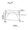
- F ig. 3 shows the relationship between the crankshaft angle and the distance traversed by the valve.
- the horizontal axis of the graph indicates the crankshaft angle, and the vertical axis indicates the distance by which the valve moves.
- the relationship achieved by the inventive system is indicated by the solid-line curves, and the relationship achieved by the conventional system is indicated by the broken-line curve.
- the valve When the crankshaft angle detected by the rotation sensor 2 reaches the timing to open the valve, the valve is controlled so as to move in the opening direction. When the timing to close the valve is reached, the valve is controlled to be seated on the valve seat 11.
- the movement of the valve is uniquely determined.
- the distance traversed by the valve can be varied as desired as illustrated.
- the R OM 10b may store a map of engine rotational speeds and distances traversed by the valve.
- the distance traversed by the valve can be varied depending on the engine rotational speed detected by the rotation sensor 2 , using the map. Since a plurality of valves in a multicylinder engine can individually be controlled, the number of cylinders that are in operation can be increased or reduced depending on the rotational speed of the engine.
- the actuating system of the present invention is also applicable to the exhaust valve, which i2 omitted from illustration.
- the system for actuating a valve in stepped movement can be used as a system for actuating intake and exhaust valves of an engine, and suitable for use with an engine which is required to vary the timing to open and close the intake and exhaust valves depending on changes in an operating condition such as the engine rotational speed.
Landscapes
- Engineering & Computer Science (AREA)
- Physics & Mathematics (AREA)
- Chemical & Material Sciences (AREA)
- Combustion & Propulsion (AREA)
- Electromagnetism (AREA)
- Power Engineering (AREA)
- Mechanical Engineering (AREA)
- General Engineering & Computer Science (AREA)
- Valve Device For Special Equipments (AREA)
- Magnetically Actuated Valves (AREA)
Abstract
Applications Claiming Priority (3)
| Application Number | Priority Date | Filing Date | Title |
|---|---|---|---|
| JP334960/88 | 1988-12-28 | ||
| JP63334960A JP2579207B2 (ja) | 1988-12-28 | 1988-12-28 | バルブのステッピング駆動装置 |
| PCT/JP1989/001335 WO1990007638A1 (fr) | 1988-12-28 | 1989-12-28 | Dispositif d'entrainement variable de soupapes |
Publications (3)
| Publication Number | Publication Date |
|---|---|
| EP0404965A1 true EP0404965A1 (fr) | 1991-01-02 |
| EP0404965A4 EP0404965A4 (en) | 1991-06-05 |
| EP0404965B1 EP0404965B1 (fr) | 1995-09-27 |
Family
ID=18283157
Family Applications (1)
| Application Number | Title | Priority Date | Filing Date |
|---|---|---|---|
| EP90901029A Expired - Lifetime EP0404965B1 (fr) | 1988-12-28 | 1989-12-28 | Dispositif d'entrainement variable de soupapes |
Country Status (5)
| Country | Link |
|---|---|
| US (1) | US5115772A (fr) |
| EP (1) | EP0404965B1 (fr) |
| JP (1) | JP2579207B2 (fr) |
| DE (1) | DE68924420T2 (fr) |
| WO (1) | WO1990007638A1 (fr) |
Cited By (4)
| Publication number | Priority date | Publication date | Assignee | Title |
|---|---|---|---|---|
| EP0542383A3 (fr) * | 1991-11-12 | 1994-10-12 | Kendall & Co | Dispositif de compression. |
| DE4400822A1 (de) * | 1994-01-13 | 1995-07-20 | Bayerische Motoren Werke Ag | Elektromagnetische Antriebsvorrichtung für ein linear bewegliches Teil |
| EP1251529A1 (fr) * | 2001-04-20 | 2002-10-23 | Renault s.a.s. | Dispositif d'entraínement linéaire d'une soupape au moyen d'aimants permanents |
| EP1712746A1 (fr) * | 2005-04-15 | 2006-10-18 | Schaeffler KG | Dispositif d'actionnnement electrique pour actionnement variable d'une soupape |
Families Citing this family (25)
| Publication number | Priority date | Publication date | Assignee | Title |
|---|---|---|---|---|
| DE3903132A1 (de) * | 1989-02-02 | 1990-08-09 | Weichhart Gmbh | Verfahren und vorrichtung zum verformen von metallrohren zu konusfoermigen oder sich verjuengenden koerpern |
| JP2639587B2 (ja) * | 1989-03-30 | 1997-08-13 | 株式会社いすゞセラミックス研究所 | バルブのステッピング駆動装置 |
| JP2756319B2 (ja) * | 1989-09-28 | 1998-05-25 | 株式会社鷺宮製作所 | 電動式流量制御弁 |
| JPH03113183A (ja) * | 1989-09-28 | 1991-05-14 | Saginomiya Seisakusho Inc | 電動式流量制御弁 |
| JPH03112180U (fr) * | 1990-03-01 | 1991-11-15 | ||
| GB9016600D0 (en) * | 1990-07-27 | 1990-09-12 | Richards Keith L | Improvements in or relating to an internal combustion engine |
| US5588403A (en) * | 1992-11-04 | 1996-12-31 | Williams; Douglas J. | Rack and pinion valve operating system |
| US5515818A (en) * | 1993-12-15 | 1996-05-14 | Machine Research Corporation Of Chicago | Electromechanical variable valve actuator |
| US5730091A (en) * | 1996-11-12 | 1998-03-24 | Ford Global Technologies, Inc. | Soft landing electromechanically actuated engine valve |
| US5645019A (en) * | 1996-11-12 | 1997-07-08 | Ford Global Technologies, Inc. | Electromechanically actuated valve with soft landing and consistent seating force |
| US5647311A (en) * | 1996-11-12 | 1997-07-15 | Ford Global Technologies, Inc. | Electromechanically actuated valve with multiple lifts and soft landing |
| US5765513A (en) * | 1996-11-12 | 1998-06-16 | Ford Global Technologies, Inc. | Electromechanically actuated valve |
| US5692463A (en) * | 1996-11-12 | 1997-12-02 | Ford Global Technologies, Inc. | Electromechanically actuated valve with multiple lifts |
| US5769043A (en) * | 1997-05-08 | 1998-06-23 | Siemens Automotive Corporation | Method and apparatus for detecting engine valve motion |
| US6039014A (en) * | 1998-06-01 | 2000-03-21 | Eaton Corporation | System and method for regenerative electromagnetic engine valve actuation |
| US6009841A (en) * | 1998-08-10 | 2000-01-04 | Ford Global Technologies, Inc. | Internal combustion engine having hybrid cylinder valve actuation system |
| JP2004518841A (ja) * | 2000-07-24 | 2004-06-24 | コンパクト ダイナミックス ゲゼルシャフト ミット ベシュレンクテル ハフツング | バルブ制御燃焼機関用のガス交換バルブ駆動装置 |
| JP4594311B2 (ja) * | 2003-05-26 | 2010-12-08 | コンティネンタル・テーベス・アクチエンゲゼルシヤフト・ウント・コンパニー・オッフェネ・ハンデルスゲゼルシヤフト | ガス交換弁のための弁駆動体 |
| WO2004113687A1 (fr) * | 2003-06-26 | 2004-12-29 | Continental Teves Ag & Co. Ohg | Mecanisme de commande destine a une soupape de changement des gaz |
| US8047166B2 (en) * | 2008-04-02 | 2011-11-01 | General Electric Company | Electric valve actuation system |
| US8191857B2 (en) * | 2008-10-09 | 2012-06-05 | Parker-Hannifin Corporation | Linear motor valve |
| IT1395581B1 (it) * | 2009-09-12 | 2012-10-16 | Gen Electric | Sistema di azionamento per valvola elettrica |
| ITRM20100533A1 (it) * | 2010-10-11 | 2011-01-10 | Danilo Ciatti | Sistema elettromagnetico di comando delle valvole per motori a combustione |
| FR2984633B1 (fr) * | 2011-12-16 | 2015-11-06 | F Q N K | Actionneur electromagnetique |
| US20180114623A1 (en) * | 2016-10-21 | 2018-04-26 | Hamilton Sundstrand Corporation | Electromagnetic actuator with ferromagnetic plunger |
Family Cites Families (13)
| Publication number | Priority date | Publication date | Assignee | Title |
|---|---|---|---|---|
| FR915876A (fr) * | 1943-08-18 | 1946-11-20 | Robey & Co Ltd | Dispositif pour commander électriquement les soupapes et la pompe d'injection des moteurs à combustion interne |
| JPS5623507A (en) * | 1979-08-02 | 1981-03-05 | Toshiba Corp | Exhaust valve |
| JPS5748603U (fr) * | 1980-09-04 | 1982-03-18 | ||
| JPS58183805A (ja) * | 1982-04-20 | 1983-10-27 | Honda Motor Co Ltd | 内燃機関のバルブ機構 |
| JPS58195004A (ja) * | 1982-05-11 | 1983-11-14 | Kenji Igari | 原動機の吸・排気コントロ−ルシステム |
| JPS59162312A (ja) * | 1983-03-08 | 1984-09-13 | Mikuni Kogyo Co Ltd | 電子制御エンジン |
| JPS6012A (ja) * | 1983-06-15 | 1985-01-05 | 住友電気工業株式会社 | 平角絶縁電線の製造方法 |
| JPS6176713A (ja) * | 1984-09-21 | 1986-04-19 | Mazda Motor Corp | エンジンのバルブ制御装置 |
| JPS6188760A (ja) * | 1984-10-05 | 1986-05-07 | Shiimensu Kk | リニアパルスモ−タ |
| DE3513103A1 (de) * | 1985-04-12 | 1986-10-16 | Fleck, Andreas, 2000 Hamburg | Elektromagnetisch arbeitende stellvorrichtung |
| FR2616481A1 (fr) * | 1987-06-12 | 1988-12-16 | Hamon Francois | Dispositif electronique de commande de soupapes de moteur a combustion interne et procedes de mise en oeuvre |
| US4829947A (en) * | 1987-08-12 | 1989-05-16 | General Motors Corporation | Variable lift operation of bistable electromechanical poppet valve actuator |
| JP2639587B2 (ja) * | 1989-03-30 | 1997-08-13 | 株式会社いすゞセラミックス研究所 | バルブのステッピング駆動装置 |
-
1988
- 1988-12-28 JP JP63334960A patent/JP2579207B2/ja not_active Expired - Lifetime
-
1989
- 1989-12-28 US US07/571,529 patent/US5115772A/en not_active Expired - Fee Related
- 1989-12-28 DE DE68924420T patent/DE68924420T2/de not_active Expired - Fee Related
- 1989-12-28 EP EP90901029A patent/EP0404965B1/fr not_active Expired - Lifetime
- 1989-12-28 WO PCT/JP1989/001335 patent/WO1990007638A1/fr not_active Ceased
Cited By (5)
| Publication number | Priority date | Publication date | Assignee | Title |
|---|---|---|---|---|
| EP0542383A3 (fr) * | 1991-11-12 | 1994-10-12 | Kendall & Co | Dispositif de compression. |
| DE4400822A1 (de) * | 1994-01-13 | 1995-07-20 | Bayerische Motoren Werke Ag | Elektromagnetische Antriebsvorrichtung für ein linear bewegliches Teil |
| EP1251529A1 (fr) * | 2001-04-20 | 2002-10-23 | Renault s.a.s. | Dispositif d'entraínement linéaire d'une soupape au moyen d'aimants permanents |
| FR2823902A1 (fr) * | 2001-04-20 | 2002-10-25 | Renault | Dispositif d'entrainement lineaire d'une soupape au moyen d'aimants permanents |
| EP1712746A1 (fr) * | 2005-04-15 | 2006-10-18 | Schaeffler KG | Dispositif d'actionnnement electrique pour actionnement variable d'une soupape |
Also Published As
| Publication number | Publication date |
|---|---|
| EP0404965B1 (fr) | 1995-09-27 |
| JPH02176287A (ja) | 1990-07-09 |
| WO1990007638A1 (fr) | 1990-07-12 |
| DE68924420T2 (de) | 1996-04-11 |
| US5115772A (en) | 1992-05-26 |
| DE68924420D1 (de) | 1995-11-02 |
| EP0404965A4 (en) | 1991-06-05 |
| JP2579207B2 (ja) | 1997-02-05 |
Similar Documents
| Publication | Publication Date | Title |
|---|---|---|
| EP0404965B1 (fr) | Dispositif d'entrainement variable de soupapes | |
| US5069422A (en) | Electromagnetic force valve driving apparatus | |
| EP0409996B1 (fr) | Systeme electromagnetique d'actionnement de soupapes | |
| EP0422228B1 (fr) | Element electromagnetique d'actionnement de soupapes | |
| US4984541A (en) | Valve stepping drive apparatus | |
| US5515818A (en) | Electromechanical variable valve actuator | |
| JP3629362B2 (ja) | エンジンバルブ駆動用電磁バルブの駆動方法 | |
| EP0406443B1 (fr) | Element electromagnetique d'actionnement de soupapes | |
| EP0406444B1 (fr) | Element electromagnetique d'actionnement de soupapes | |
| EP0401390A1 (fr) | Element electromagnetique d'actionnement de soupapes | |
| US10774696B2 (en) | Highly efficient linear motor | |
| JP2606740B2 (ja) | バルブのステッピング駆動装置 | |
| JP2772569B2 (ja) | 電磁力バルブ駆動装置 | |
| JP2620135B2 (ja) | バルブのステッピング駆動装置 | |
| JP2566474B2 (ja) | 電磁力バルブ駆動装置 | |
| JP2855352B2 (ja) | 作動位置検出式電磁力バルブ駆動装置 | |
| JP2673370B2 (ja) | バルブの駆動装置 | |
| JP2787342B2 (ja) | 誘導式電磁力バルブ駆動装置 | |
| JP2610186B2 (ja) | バルブのステッピング駆動装置 | |
| JPH0347412A (ja) | 電磁力バルブ駆動装置 | |
| JPH0392516A (ja) | 電磁バルブの可動磁極 | |
| JP3040784B2 (ja) | 誘導式電磁力バルブ駆動装置 | |
| JPH02286813A (ja) | バルブの駆動装置 | |
| JPH0347411A (ja) | 電磁力バルブ駆動装置 | |
| JPH03182609A (ja) | 電磁力バルブ駆動装置 |
Legal Events
| Date | Code | Title | Description |
|---|---|---|---|
| PUAI | Public reference made under article 153(3) epc to a published international application that has entered the european phase |
Free format text: ORIGINAL CODE: 0009012 |
|
| 17P | Request for examination filed |
Effective date: 19900920 |
|
| AK | Designated contracting states |
Kind code of ref document: A1 Designated state(s): DE FR GB |
|
| A4 | Supplementary search report drawn up and despatched |
Effective date: 19910416 |
|
| AK | Designated contracting states |
Kind code of ref document: A4 Designated state(s): DE FR GB |
|
| 17Q | First examination report despatched |
Effective date: 19920630 |
|
| GRAA | (expected) grant |
Free format text: ORIGINAL CODE: 0009210 |
|
| AK | Designated contracting states |
Kind code of ref document: B1 Designated state(s): DE FR GB |
|
| REF | Corresponds to: |
Ref document number: 68924420 Country of ref document: DE Date of ref document: 19951102 |
|
| ET | Fr: translation filed | ||
| PLBE | No opposition filed within time limit |
Free format text: ORIGINAL CODE: 0009261 |
|
| STAA | Information on the status of an ep patent application or granted ep patent |
Free format text: STATUS: NO OPPOSITION FILED WITHIN TIME LIMIT |
|
| 26N | No opposition filed | ||
| PGFP | Annual fee paid to national office [announced via postgrant information from national office to epo] |
Ref country code: FR Payment date: 19961211 Year of fee payment: 8 |
|
| PGFP | Annual fee paid to national office [announced via postgrant information from national office to epo] |
Ref country code: GB Payment date: 19961219 Year of fee payment: 8 |
|
| PGFP | Annual fee paid to national office [announced via postgrant information from national office to epo] |
Ref country code: DE Payment date: 19970107 Year of fee payment: 8 |
|
| PG25 | Lapsed in a contracting state [announced via postgrant information from national office to epo] |
Ref country code: GB Free format text: LAPSE BECAUSE OF NON-PAYMENT OF DUE FEES Effective date: 19971228 |
|
| PG25 | Lapsed in a contracting state [announced via postgrant information from national office to epo] |
Ref country code: FR Free format text: THE PATENT HAS BEEN ANNULLED BY A DECISION OF A NATIONAL AUTHORITY Effective date: 19971231 |
|
| GBPC | Gb: european patent ceased through non-payment of renewal fee |
Effective date: 19971228 |
|
| PG25 | Lapsed in a contracting state [announced via postgrant information from national office to epo] |
Ref country code: DE Free format text: LAPSE BECAUSE OF NON-PAYMENT OF DUE FEES Effective date: 19980901 |
|
| REG | Reference to a national code |
Ref country code: FR Ref legal event code: ST |