EP0405130A1 - Aiguille à clapet pour machines à formation de produits maillés - Google Patents
Aiguille à clapet pour machines à formation de produits maillés Download PDFInfo
- Publication number
- EP0405130A1 EP0405130A1 EP90109546A EP90109546A EP0405130A1 EP 0405130 A1 EP0405130 A1 EP 0405130A1 EP 90109546 A EP90109546 A EP 90109546A EP 90109546 A EP90109546 A EP 90109546A EP 0405130 A1 EP0405130 A1 EP 0405130A1
- Authority
- EP
- European Patent Office
- Prior art keywords
- needle
- tongue
- latch
- symmetry
- shaft
- Prior art date
- Legal status (The legal status is an assumption and is not a legal conclusion. Google has not performed a legal analysis and makes no representation as to the accuracy of the status listed.)
- Granted
Links
- 239000004744 fabric Substances 0.000 title claims abstract description 5
- 230000001154 acute effect Effects 0.000 claims abstract description 16
- 238000004519 manufacturing process Methods 0.000 claims description 4
- 230000007704 transition Effects 0.000 claims description 3
- 210000002105 tongue Anatomy 0.000 description 75
- 238000009940 knitting Methods 0.000 description 18
- 230000015572 biosynthetic process Effects 0.000 description 4
- 238000000034 method Methods 0.000 description 3
- 229910000831 Steel Inorganic materials 0.000 description 2
- 238000010276 construction Methods 0.000 description 2
- 239000010959 steel Substances 0.000 description 2
- 210000000481 breast Anatomy 0.000 description 1
- 230000001680 brushing effect Effects 0.000 description 1
- 210000000038 chest Anatomy 0.000 description 1
- 238000009434 installation Methods 0.000 description 1
- 239000002184 metal Substances 0.000 description 1
- 230000000284 resting effect Effects 0.000 description 1
- 230000000717 retained effect Effects 0.000 description 1
Images

Classifications
-
- D—TEXTILES; PAPER
- D04—BRAIDING; LACE-MAKING; KNITTING; TRIMMINGS; NON-WOVEN FABRICS
- D04B—KNITTING
- D04B35/00—Details of, or auxiliary devices incorporated in, knitting machines, not otherwise provided for
- D04B35/02—Knitting tools or instruments not provided for in group D04B15/00 or D04B27/00
- D04B35/04—Latch needles
Definitions
- the invention relates to a latch needle for machines for the manufacture of knitted fabrics, with a needle shaft, a needle head and a needle tongue pivotally mounted in a tongue slot of the needle shaft about a transverse tongue axis.
- the tongue needle is designed with a reduced shaft height in its front shaft region facing the head.
- the shaft height between the needle foot and throat is kept as small as possible. Because of this low shaft height, the stability of the latch needle in the shaft region adjoining the head is correspondingly reduced.
- the needle Under the influence of lateral forces which act on the head and the throat area of the needle during the stitch formation process and originate, inter alia, from the goods take-off device, the needle is not only removed from its symmetrical position by the predetermined amount corresponding to the necessary play between the needle bed walls and the needle shaft moved to the corresponding needle bed wall, but the stitch-forming part of the latch needle protruding from the needle bed is inevitably elastically pushed aside somewhat from its originally central position. A needle tongue which is no longer exactly aligned with the hook tip with its spoon is thus brought up to the adjacent knitting tool, for example a circuit board, so that it touches the knitting tool with its tongue spoon during its pivoting movement.
- the adjacent knitting tool for example a circuit board
- the object of the invention is therefore to provide a latch needle, the needle tongue of which regardless of the hinge length and with a low needle shaft even after a long period of use under the action of lateral forces closes perfectly on the needle head and remains so close to the longitudinal plane of symmetry of the needle during its pivoting movement that rubbing against adjacent knitting tools, in particular sinkers, is reliably prevented.
- the latch needle mentioned at the outset is characterized according to the invention in that the latch slot is arranged with its longitudinal plane of symmetry including an acute angle with the longitudinal plane of symmetry of the needle shaft.
- the tongue slot with its longitudinal plane of symmetry is not arranged lying in the center plane of the needle, when the needle is appropriately installed in the machine, it is ensured that under the action of the lateral forces occurring during the stitch formation process, the needle tongue during its pivoting movement with its spoon is not substantially above the plane of needle symmetry, ie can be pushed out to the side so far that it brushes against the adjacent knitting tool. At the same time, the flawless, essentially central support of the tongue spoon on the needle head is retained.
- the tongue slot with its longitudinal plane of symmetry can be arranged pivoted toward the needle sides with respect to the longitudinal plane of symmetry of the needle shaft with respect to the longitudinal plane of symmetry of the needle shaft, so that the tongue slot is inclined in the plan view of the needle upper side.
- the arrangement can also be such that the tongue slot with its longitudinal plane of symmetry extends around a longitudinal axis in the needle shaft Axis is laterally tilted.
- the acute angle enclosed between the longitudinal plane of symmetry, the needle tongue and the longitudinal plane of symmetry of the needle shaft which is characteristic of the lateral pivoting and / or tilting of the longitudinal plane of symmetry of the tongue slot, can expediently lie with its apex in the area of the tongue slot.
- embodiments are also conceivable in which the apex of this acute angle comes to lie outside the latch slot.
- the size of the acute angle depends, among other things. on the jaw height, the needle shaft thickness and the installation conditions of the needle in the associated knitting machine. It is advantageously between 0.5 ° and 6 °.
- the needle shaft in the region of the transition to the throat may have at least one elevation on its upper side, which provides the needle with improved support by securely resting against the needle bed walls Gives the machine a needle bed.
- the elevation can prevent the needle in its shaft region adjacent to the needle head from operating under critical conditions, under the influence of lateral forces, beyond the amount dictated by the inevitable play between the tongue needle and the needle bed walls in the direction of the needle bed wall opposite the rotational movement of the needle cylinder about its longitudinal axis tilts.
- the protruding from the needle bed The stitch-forming part of the latch needle with the needle head and needle tongue is thereby additionally held in a position appropriate for a trouble-free workflow.
- Machines for the production of knitted fabrics are preferably knitting and knitting machines, but in particular circular knitting and knitting machines, which work with latch needles and in which, due to the technological circumstances, for example due to the rotary movement of the needle cylinder and the dial or, as a result of the goods take-off, lateral forces acting on the needle head and / or tongue and the subsequent needle shaft region occur.
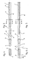
- the latch needle shown in FIG. 1 using the designation according to DIN ISO 8119, has a needle shaft 1 which carries a foot 2 at one end and a needle head or hook 3 at the other end.
- a longitudinal tongue slot 8 is formed in the needle shaft 1 in the region of the breast designated by 4, which is followed by a throat 6 on the upper side 7 of the needle.
- the tongue slot 8 has an opening 10 which opens toward the needle back 9 and is arranged approximately below the tongue axis 120.
- a needle tongue 11 is pivotally mounted in the tongue slot 8 about a transverse tongue axis 120.
- the needle tongue 11 is formed at its end facing away from the tongue axis 120 with a tongue spoon 12 which is seated on a tongue shaft 13 which dips into the tongue slot 8 and has the bearing bore for the tongue axis 120.
- the tongue spoon 12 lies centrally on the hook tip 14.
- the elongated, laterally parallel flanked tongue slot 8 is milled into the needle shaft 1 punched out of sheet metal (steel strip) or made of steel wire such that its longitudinal plane of symmetry 15 includes an acute angle with the longitudinal plane of symmetry 16 of the needle shaft 1.
- the tongue slot 8 with its longitudinal plane of symmetry 15 is pivoted obliquely toward the needle shaft sides 18, 19 with respect to the longitudinal plane of symmetry 16 of the needle shaft 1 with its longitudinal plane of symmetry 15 about a vertical axis 17 extending from the needle upper side 7 to the needle back 9 arranged, the tip enclosed between the two longitudinal symmetry planes 15, 16 Angle is designated 20.
- the vertical axis 17 runs through the opening 10; it is aligned parallel to the side flanks of the tongue slot 8, which means that the apex of the acute angle 20 lies within the area of the tongue slot 8.
- the tongue slot 8 with its longitudinal plane of symmetry 15 is arranged laterally tilted about an axis 21 (FIG. 6) extending in the longitudinal direction of the needle shaft, so that the one between the two Longitudinal symmetry planes 15, 16 included acute angles 20a result from FIG. 6.
- the acute angle 20 or 20a is of the order of 0.5 ° to 6 °; In exceptional cases, deviations from this area are possible on both sides.
- the arrangement of the tongue slot 8 according to the embodiment according to FIGS. 3, 4 can also be combined with that according to the embodiment according to FIGS. 5, 6, such that the tongue slot 8 lies "skewed" in the needle shaft 1 and accordingly both acute angle 20 and the acute angle 20a between the two longitudinal symmetry planes 15, 16 occurs.
- these two acute angles 20, 20a can be of the same or preferably different sizes.
- the needle tongue 11 which is guided laterally with its tongue shaft 13 in the tongue slot 8, comes to lie in the closed position in the rest position in such a way that its spoon is displaced to one side on the hook tip 14 rests.
- the latch needle shown in FIGS. 3, 5 is inserted, for example, into the needle cylinder of a circular knitting machine rotating clockwise, as indicated by an arrow 22 in FIG. 5, the needle tongue 11 and somewhat also the needle head 3 are counteracted by the acting side forces the direction of the arrow is bent somewhat elastically to the side, the needle shaft 1 being pressed against the associated side wall of the needle bed on the needle side 19 located at the rear in the direction of rotation.
- the tongue spoon 12 Due to the inclined or tilted position of the tongue slot 8, however, it is ensured that the tongue spoon 12 covers the hook tip 14 properly and with its longitudinal plane of symmetry 15 cannot be pushed laterally beyond the longitudinal symmetry plane 16 of the needle shaft 1 in the direction of rotation 22. This certainly precludes the tongue spoon 12 from brushing against an adjacent plate, etc., even when finely divided.
- the two described embodiments of the latch needle have a toothed tongue spoon 12.
- the invention can also be used to the same extent for latch needles with a toothed needle head 3, as it is independent of the design of the contact surface of the needle tongue on the needle head.
- the needle shaft 1 is provided on the upper side 7 in the area of the transition to the throat 6 with an elevation 23, which may also be shorter or may be replaced by several elevations of the same type arranged one behind the other.
- This elevation 23, which may also be considerably shorter than shown in the drawing, prevents the latch needle in its relatively low shaft area adjoining the throat 6 under the action of the lateral forces acting on the needle head 3 between the needle bed walls by an amount beyond the operationally necessary play is tilted or wound to such an extent that under difficult operating conditions there is still the risk of the needle tongue being touched 11 occurs on the adjacent board, etc.
- the stitch-forming part of the latch needle with the needle head 3 and the latch 11 protruding from the needle cylinder is thereby held in the correct position in the needle bed for a trouble-free workflow even under these conditions.
Landscapes
- Engineering & Computer Science (AREA)
- Textile Engineering (AREA)
- Knitting Machines (AREA)
Applications Claiming Priority (2)
| Application Number | Priority Date | Filing Date | Title |
|---|---|---|---|
| DE3921458A DE3921458C1 (fr) | 1989-06-30 | 1989-06-30 | |
| DE3921458 | 1989-06-30 |
Publications (2)
| Publication Number | Publication Date |
|---|---|
| EP0405130A1 true EP0405130A1 (fr) | 1991-01-02 |
| EP0405130B1 EP0405130B1 (fr) | 1993-10-13 |
Family
ID=6383968
Family Applications (1)
| Application Number | Title | Priority Date | Filing Date |
|---|---|---|---|
| EP90109546A Expired - Lifetime EP0405130B1 (fr) | 1989-06-30 | 1990-05-19 | Aiguille à clapet pour machines à formation de produits maillés |
Country Status (6)
| Country | Link |
|---|---|
| US (1) | US5090218A (fr) |
| EP (1) | EP0405130B1 (fr) |
| JP (1) | JPH03220349A (fr) |
| CA (1) | CA2020046C (fr) |
| DE (2) | DE3921458C1 (fr) |
| ES (1) | ES2045641T3 (fr) |
Families Citing this family (5)
| Publication number | Priority date | Publication date | Assignee | Title |
|---|---|---|---|---|
| EP1146157B1 (fr) * | 2000-04-15 | 2004-07-14 | Groz-Beckert KG | Aiguille à clapet avec espace de fil amélioré |
| EP1767678B1 (fr) * | 2005-09-22 | 2008-03-26 | Groz-Beckert KG | Aiguille à tricoter pour métier à tricoter |
| US7757516B1 (en) | 2005-11-21 | 2010-07-20 | Hbi Branded Apparel Enterprises, Llc | Abrasive knitting needle and sinker |
| US7634922B2 (en) * | 2005-11-21 | 2009-12-22 | Hbi Branded Apparel Enterprises, Llc | Knitting needle for knitting sueded fabrics and methods of knitting sueded fabrics |
| US7757515B1 (en) | 2009-03-11 | 2010-07-20 | Hbi Branded Apparel Enterprises, Llc | Cut pile fabric and method of making same |
Citations (2)
| Publication number | Priority date | Publication date | Assignee | Title |
|---|---|---|---|---|
| DE672512C (de) * | 1936-10-18 | 1939-03-04 | Dubied & Cie Sa E | Strickmaschinennadel |
| DE3140386A1 (de) * | 1981-10-10 | 1983-04-28 | Theodor Groz & Söhne & Ernst Beckert Nadelfabrik KG, 7470 Albstadt | "zungennadel fuer maschinen zur herstellung von maschenware" |
Family Cites Families (5)
| Publication number | Priority date | Publication date | Assignee | Title |
|---|---|---|---|---|
| US1764342A (en) * | 1929-07-03 | 1930-06-17 | Gotham Knitbac Machine Corp | Knitting needle |
| DE586678C (de) * | 1932-02-21 | 1933-10-24 | Franz Meiwald | Strickmaschine mit Zungennadeln |
| JPS6059337A (ja) * | 1983-09-13 | 1985-04-05 | Fuji Xerox Co Ltd | 複写機の複写倍率変倍装置 |
| JPS6217514U (fr) * | 1985-07-13 | 1987-02-02 | ||
| JPS63177977U (fr) * | 1987-05-06 | 1988-11-17 |
-
1989
- 1989-06-30 DE DE3921458A patent/DE3921458C1/de not_active Expired - Lifetime
-
1990
- 1990-05-19 EP EP90109546A patent/EP0405130B1/fr not_active Expired - Lifetime
- 1990-05-19 ES ES90109546T patent/ES2045641T3/es not_active Expired - Lifetime
- 1990-05-19 DE DE90109546T patent/DE59003059D1/de not_active Expired - Fee Related
- 1990-06-28 CA CA002020046A patent/CA2020046C/fr not_active Expired - Fee Related
- 1990-06-29 JP JP2170369A patent/JPH03220349A/ja active Granted
- 1990-07-02 US US07/546,938 patent/US5090218A/en not_active Expired - Lifetime
Patent Citations (2)
| Publication number | Priority date | Publication date | Assignee | Title |
|---|---|---|---|---|
| DE672512C (de) * | 1936-10-18 | 1939-03-04 | Dubied & Cie Sa E | Strickmaschinennadel |
| DE3140386A1 (de) * | 1981-10-10 | 1983-04-28 | Theodor Groz & Söhne & Ernst Beckert Nadelfabrik KG, 7470 Albstadt | "zungennadel fuer maschinen zur herstellung von maschenware" |
Also Published As
| Publication number | Publication date |
|---|---|
| CA2020046C (fr) | 1993-04-06 |
| JPH055939B2 (fr) | 1993-01-25 |
| DE3921458C1 (fr) | 1990-09-27 |
| DE59003059D1 (de) | 1993-11-18 |
| CA2020046A1 (fr) | 1990-12-31 |
| US5090218A (en) | 1992-02-25 |
| EP0405130B1 (fr) | 1993-10-13 |
| JPH03220349A (ja) | 1991-09-27 |
| ES2045641T3 (es) | 1994-01-16 |
Similar Documents
| Publication | Publication Date | Title |
|---|---|---|
| EP1039003B1 (fr) | Aiguille à coulisse double | |
| EP0278053B1 (fr) | Aiguille à clapet pour des machines textiles formant des mailles | |
| EP1368520B1 (fr) | Dispositif de formation de mailles sur machine | |
| EP1028185B1 (fr) | Aiguille de transfert pour le transfert de maille | |
| EP0405130B1 (fr) | Aiguille à clapet pour machines à formation de produits maillés | |
| EP2159311B1 (fr) | Aiguille à crochet dotée d'une section en ellipse oblique du crochet | |
| EP0270780B1 (fr) | Crochet pour machine à relier, machine à broder et analogue | |
| DE19720169C2 (de) | Auswahlplatine | |
| DE2745793C3 (de) | Tufting-Maschine | |
| DE102006004098B3 (de) | Barre einer Wirkmaschine | |
| DE2110916A1 (de) | Arbeitselement einer Strickmaschine mit mindestens einem Nadelfuss | |
| EP0073380B1 (fr) | Outil de tricotage estampé pour des métiers à tricoter | |
| EP0405085B1 (fr) | Outil pour des machines formant des mailles, notamment des machines à tricoter | |
| EP2009160A1 (fr) | Aiguille coupante dotée d'une lame réglable | |
| DE3212622A1 (de) | Garntraeger fuer eine rundstrickmaschine | |
| DE3029333A1 (de) | Filznadel | |
| EP0077022B1 (fr) | Aiguille à palette pour la fabrication d'articles de bonneterie | |
| DE1635907B1 (de) | Zungennadel | |
| DE3512775C2 (fr) | ||
| DE4402707C2 (de) | Schneidwerkzeug für maschenbildende Textilmaschinen, insbesondere zur Herstellung von Plüschware | |
| DE19519671C2 (de) | Schiebernadel für Kettenwirk-, insbesondere Nähwirkmaschinen | |
| DE3421868C2 (de) | Fadenzufuhreinrichtung für Strick- oder Wirkmaschinen | |
| DE1149482B (de) | Rundstrickmaschine | |
| DE7537472U (de) | Nadel fuer strickmaschinen | |
| CH215641A (de) | Nadel für Wirkmaschinen. |
Legal Events
| Date | Code | Title | Description |
|---|---|---|---|
| PUAI | Public reference made under article 153(3) epc to a published international application that has entered the european phase |
Free format text: ORIGINAL CODE: 0009012 |
|
| AK | Designated contracting states |
Kind code of ref document: A1 Designated state(s): CH DE ES FR GB IT LI |
|
| 17P | Request for examination filed |
Effective date: 19910606 |
|
| 17Q | First examination report despatched |
Effective date: 19930224 |
|
| GRAA | (expected) grant |
Free format text: ORIGINAL CODE: 0009210 |
|
| AK | Designated contracting states |
Kind code of ref document: B1 Designated state(s): CH DE ES FR GB IT LI |
|
| ITF | It: translation for a ep patent filed | ||
| REF | Corresponds to: |
Ref document number: 59003059 Country of ref document: DE Date of ref document: 19931118 |
|
| REG | Reference to a national code |
Ref country code: ES Ref legal event code: FG2A Ref document number: 2045641 Country of ref document: ES Kind code of ref document: T3 |
|
| GBT | Gb: translation of ep patent filed (gb section 77(6)(a)/1977) |
Effective date: 19940106 |
|
| ET | Fr: translation filed | ||
| PLBE | No opposition filed within time limit |
Free format text: ORIGINAL CODE: 0009261 |
|
| STAA | Information on the status of an ep patent application or granted ep patent |
Free format text: STATUS: NO OPPOSITION FILED WITHIN TIME LIMIT |
|
| 26N | No opposition filed | ||
| REG | Reference to a national code |
Ref country code: CH Ref legal event code: PFA Free format text: THEODOR GROZ & SOEHNE & ERNST BECKERT NADELFABRIK COMMANDIT-GESELLSCHAFT TRANSFER- GROZ-BECKERT KOMMANDITGESELLSCHAFT |
|
| REG | Reference to a national code |
Ref country code: FR Ref legal event code: CD |
|
| REG | Reference to a national code |
Ref country code: ES Ref legal event code: PC2A |
|
| REG | Reference to a national code |
Ref country code: GB Ref legal event code: IF02 |
|
| PGFP | Annual fee paid to national office [announced via postgrant information from national office to epo] |
Ref country code: CH Payment date: 20080515 Year of fee payment: 19 Ref country code: ES Payment date: 20080529 Year of fee payment: 19 Ref country code: DE Payment date: 20080531 Year of fee payment: 19 |
|
| PGFP | Annual fee paid to national office [announced via postgrant information from national office to epo] |
Ref country code: IT Payment date: 20080527 Year of fee payment: 19 |
|
| PGFP | Annual fee paid to national office [announced via postgrant information from national office to epo] |
Ref country code: GB Payment date: 20080522 Year of fee payment: 19 |
|
| REG | Reference to a national code |
Ref country code: CH Ref legal event code: PL |
|
| GBPC | Gb: european patent ceased through non-payment of renewal fee |
Effective date: 20090519 |
|
| PG25 | Lapsed in a contracting state [announced via postgrant information from national office to epo] |
Ref country code: LI Free format text: LAPSE BECAUSE OF NON-PAYMENT OF DUE FEES Effective date: 20090531 Ref country code: CH Free format text: LAPSE BECAUSE OF NON-PAYMENT OF DUE FEES Effective date: 20090531 |
|
| REG | Reference to a national code |
Ref country code: FR Ref legal event code: ST Effective date: 20100129 |
|
| PG25 | Lapsed in a contracting state [announced via postgrant information from national office to epo] |
Ref country code: FR Free format text: LAPSE BECAUSE OF NON-PAYMENT OF DUE FEES Effective date: 20090602 |
|
| PGFP | Annual fee paid to national office [announced via postgrant information from national office to epo] |
Ref country code: FR Payment date: 20080425 Year of fee payment: 19 |
|
| PG25 | Lapsed in a contracting state [announced via postgrant information from national office to epo] |
Ref country code: GB Free format text: LAPSE BECAUSE OF NON-PAYMENT OF DUE FEES Effective date: 20090519 |
|
| PG25 | Lapsed in a contracting state [announced via postgrant information from national office to epo] |
Ref country code: DE Free format text: LAPSE BECAUSE OF NON-PAYMENT OF DUE FEES Effective date: 20091201 |
|
| REG | Reference to a national code |
Ref country code: ES Ref legal event code: FD2A Effective date: 20090520 |
|
| PG25 | Lapsed in a contracting state [announced via postgrant information from national office to epo] |
Ref country code: ES Free format text: LAPSE BECAUSE OF NON-PAYMENT OF DUE FEES Effective date: 20090520 |
|
| PG25 | Lapsed in a contracting state [announced via postgrant information from national office to epo] |
Ref country code: IT Free format text: LAPSE BECAUSE OF NON-PAYMENT OF DUE FEES Effective date: 20090519 |