EP0405207A2 - Vorrichtung zum Kuppeln einer Bohrstange für Schachtofenabstichlöcher mit dem Arbeitswerkzeug einer Bohrmaschine - Google Patents
Vorrichtung zum Kuppeln einer Bohrstange für Schachtofenabstichlöcher mit dem Arbeitswerkzeug einer Bohrmaschine Download PDFInfo
- Publication number
- EP0405207A2 EP0405207A2 EP90110951A EP90110951A EP0405207A2 EP 0405207 A2 EP0405207 A2 EP 0405207A2 EP 90110951 A EP90110951 A EP 90110951A EP 90110951 A EP90110951 A EP 90110951A EP 0405207 A2 EP0405207 A2 EP 0405207A2
- Authority
- EP
- European Patent Office
- Prior art keywords
- rod
- plug
- piston
- clamp
- spring
- Prior art date
- Legal status (The legal status is an assumption and is not a legal conclusion. Google has not performed a legal analysis and makes no representation as to the accuracy of the status listed.)
- Granted
Links
- 238000005553 drilling Methods 0.000 title claims description 5
- 230000008878 coupling Effects 0.000 title claims description 4
- 238000010168 coupling process Methods 0.000 title claims description 4
- 238000005859 coupling reaction Methods 0.000 title claims description 4
- 239000012530 fluid Substances 0.000 claims description 4
- 230000035515 penetration Effects 0.000 claims description 3
- 238000005266 casting Methods 0.000 claims description 2
- 238000000034 method Methods 0.000 claims description 2
- 238000000605 extraction Methods 0.000 claims 1
- 230000000903 blocking effect Effects 0.000 description 1
- 238000006243 chemical reaction Methods 0.000 description 1
- 230000006866 deterioration Effects 0.000 description 1
- 230000000149 penetrating effect Effects 0.000 description 1
- 238000009527 percussion Methods 0.000 description 1
- 238000009423 ventilation Methods 0.000 description 1
Images
Classifications
-
- C—CHEMISTRY; METALLURGY
- C21—METALLURGY OF IRON
- C21B—MANUFACTURE OF IRON OR STEEL
- C21B7/00—Blast furnaces
- C21B7/12—Opening or sealing the tap holes
-
- Y—GENERAL TAGGING OF NEW TECHNOLOGICAL DEVELOPMENTS; GENERAL TAGGING OF CROSS-SECTIONAL TECHNOLOGIES SPANNING OVER SEVERAL SECTIONS OF THE IPC; TECHNICAL SUBJECTS COVERED BY FORMER USPC CROSS-REFERENCE ART COLLECTIONS [XRACs] AND DIGESTS
- Y10—TECHNICAL SUBJECTS COVERED BY FORMER USPC
- Y10T—TECHNICAL SUBJECTS COVERED BY FORMER US CLASSIFICATION
- Y10T279/00—Chucks or sockets
- Y10T279/17—Socket type
- Y10T279/17128—Self-grasping
- Y10T279/17171—One-way-clutch type
- Y10T279/17179—Wedge
-
- Y—GENERAL TAGGING OF NEW TECHNOLOGICAL DEVELOPMENTS; GENERAL TAGGING OF CROSS-SECTIONAL TECHNOLOGIES SPANNING OVER SEVERAL SECTIONS OF THE IPC; TECHNICAL SUBJECTS COVERED BY FORMER USPC CROSS-REFERENCE ART COLLECTIONS [XRACs] AND DIGESTS
- Y10—TECHNICAL SUBJECTS COVERED BY FORMER USPC
- Y10T—TECHNICAL SUBJECTS COVERED BY FORMER US CLASSIFICATION
- Y10T408/00—Cutting by use of rotating axially moving tool
- Y10T408/94—Tool-support
- Y10T408/95—Tool-support with tool-retaining means
Definitions
- the present invention relates to a device for coupling a drilling rod from the tap hole of a shaft furnace to the working tool of a drilling machine for implementing a method according to which the closure and the opening of the taphole comprise a setting operation and an operation of extracting the piercing rod which is abandoned in the mass of the taphole between two successive castings, said device comprising a mandrel to be made integral of the working tool and which comprises a front receiving cavity for receiving the end of the piercing rod, a clamp for hanging the end of said rod in this cavity, this clamp consisting of at least two rods sliding devices arranged symmetrically around the axis of the cavity, and each carrying at one end a jaw intended to grip the end of the rod and, at the opposite end, a piston subjected, on the one hand, to the '' action of a pneumatic or hydraulic fluid to close the clamp by penetration of the jaws into the rod and, on the other hand, to elastic means acting in the direction of opening of the clamp, each of said pistons sliding in
- a device of this kind is known from French patent 2,501,857.
- the working tool is generally constituted by a pneumatic striker which can strike in both directions in order to push the piercing rod into the blocking mass before the hardening of that -this and to be able to extract it when opening the tap hole.
- Pneumatic fluid used for the striker can also be used to close the pliers when extracting the piercing rod, while when engaging the piercing rod, the pneumatic chamber of the pliers piston is ventilated to allow opening of these clamps under the action according to their elastic means.
- the object of the present invention is to provide an improved device of the type described in the preamble which does not have these drawbacks.
- the device proposed by the present invention is essentially characterized by a spring disposed between said plug and the adjacent face of the piston, said spring being powerful enough to keep the piston away from the plug against the action of said means. elastic to which it is exposed on the opposite side.
- the plug preferably has a cylindrical cavity for housing the spring.
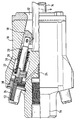
- This device comprises a mandrel 10 provided with a front cavity 12 for receiving the free end of a piercing rod 14 and a rear axial bore 16 for receiving the striker of a work tool not shown.
- the device comprises a clamp for gripping the front end of the rod 14.
- This clamp consists of two jaws arranged symmetrically around the longitudinal axis of the mandrel 1o and sliding obliquely relative to this axis 0.
- One of these jaws is represented by the reference 18, while the other which is not visible is identical to the one which is represented and functions in the same way.
- the jaw 18 is mounted on the front end of a rod 20 and is guided by the interior surface of the cavity 12.
- the rod 20 is extended in a cylindrical chamber 26 where it is integral with a piston 22.
- This piston 22 is, in the example shown, a pneumatic piston which undergoes, on the side opposite to the rod 20, the action of a pneumatic fluid penetrating into the chamber 26 via a pipe 24.
- a pneumatic piston Around the rod 20 is one or more helical springs 28 bearing, on the one hand, on the piston 22 and, on the other hand, on an inner rim of the pneumatic chamber 26.
- the pressurization of the chamber 26 through the pneumatic line 24 advances the jaw 28 up to '' with superficial penetration in the rod 14 so that a movement to the right of the mandrel 10 drives the rod 14.
- the ventilation of the chamber 26 subjects the piston 22 to the action of the spring 28 to release the jaw 18 of the rod 14. This is for example the case during the engagement nt of the rod 14 in the plugging mass of the tap hole.
- the invention proposes to have a spring 32 between the piston 22 and the plug 30.
- This comprises, at this Indeed, preferably a cylindrical chamber 34 for housing this spring 32.
- This spring 32 is powerful enough to oppose, in part, the action of the spring 28 and maintain, when the chamber 26 is ventilated, the piston 22 away from the inner surface of the plug 30 and thus avoid hammering of the plug 30 by the piston 22.
- the mandrel 10 unlike the known mandrels, is a one-piece machined mandrel which contributes to greater longevity, since it does not include a bolt and assembly screws which, in general, are very vulnerable by repeated percussion.
Landscapes
- Engineering & Computer Science (AREA)
- Chemical & Material Sciences (AREA)
- Manufacturing & Machinery (AREA)
- Materials Engineering (AREA)
- Metallurgy (AREA)
- Organic Chemistry (AREA)
- Earth Drilling (AREA)
- Blast Furnaces (AREA)
- Percussive Tools And Related Accessories (AREA)
- Gripping On Spindles (AREA)
Applications Claiming Priority (2)
| Application Number | Priority Date | Filing Date | Title |
|---|---|---|---|
| LU87546 | 1989-06-30 | ||
| LU87546A LU87546A1 (fr) | 1989-06-30 | 1989-06-30 | Dispositif d'accouplement d'une tige de percage du trou de coulee d'un four a cuve a l'outil de travail d'une machine de percage |
Publications (3)
| Publication Number | Publication Date |
|---|---|
| EP0405207A2 true EP0405207A2 (de) | 1991-01-02 |
| EP0405207A3 EP0405207A3 (en) | 1991-09-11 |
| EP0405207B1 EP0405207B1 (de) | 1994-09-28 |
Family
ID=19731170
Family Applications (1)
| Application Number | Title | Priority Date | Filing Date |
|---|---|---|---|
| EP90110951A Expired - Lifetime EP0405207B1 (de) | 1989-06-30 | 1990-06-09 | Vorrichtung zum Kuppeln einer Bohrstange für Schachtofenabstichlöcher mit dem Arbeitswerkzeug einer Bohrmaschine |
Country Status (10)
| Country | Link |
|---|---|
| US (1) | US5056968A (de) |
| EP (1) | EP0405207B1 (de) |
| JP (1) | JP2805382B2 (de) |
| AT (1) | AT403379B (de) |
| AU (1) | AU621487B2 (de) |
| BR (1) | BR9003153A (de) |
| CA (1) | CA2017415A1 (de) |
| DE (1) | DE4016035A1 (de) |
| ES (1) | ES2062186T3 (de) |
| LU (1) | LU87546A1 (de) |
Cited By (1)
| Publication number | Priority date | Publication date | Assignee | Title |
|---|---|---|---|---|
| EP0573766A1 (de) * | 1992-06-10 | 1993-12-15 | Paul Wurth S.A. | Universalspannfutter für eine Schachtofenabstichbohrmaschine |
Families Citing this family (2)
| Publication number | Priority date | Publication date | Assignee | Title |
|---|---|---|---|---|
| LU88058A1 (fr) * | 1992-01-24 | 1993-08-17 | Paul Wurth S.A. | Machine de percage d'un trou de coulee d'un four a cuve |
| FI925647A7 (fi) * | 1992-12-11 | 1994-06-12 | Outokumpu Chrome Oy | Kaasuputken syöttölaite sulaa materiaalia sisältävään uuniin |
Family Cites Families (6)
| Publication number | Priority date | Publication date | Assignee | Title |
|---|---|---|---|---|
| US3862750A (en) * | 1972-10-17 | 1975-01-28 | Inland Steel Co | Tophole opening apparatus |
| LU78756A1 (de) * | 1977-12-22 | 1978-04-17 | ||
| LU83917A1 (fr) * | 1982-02-03 | 1983-09-02 | Wurth Paul Sa | Dispositif d'accouplement d'une tige de percage du trou de coulee d'un four a cuve a l'outil de travail d'une machine de percage |
| DE3339127A1 (de) * | 1983-10-28 | 1985-05-09 | Dango & Dienenthal Maschinenbau GmbH, 5900 Siegen | Greifvorrichtung fuer in das stichloch von metallurgischen oefen eintreibbare und aus diesem herausziehbare stangen, insbesondere abstichstangen |
| JPS60169250U (ja) * | 1984-04-16 | 1985-11-09 | マツダ株式会社 | 出銑口開孔用ロツドチヤツキング装置 |
| LU87010A1 (fr) * | 1987-10-06 | 1989-05-08 | Wurth Paul Sa | Dispositif de montage d'une pince pour l'accouplement d'une tige de percage du trou de coulee d'un four a cuve a une machine de percage |
-
1989
- 1989-06-30 LU LU87546A patent/LU87546A1/fr unknown
-
1990
- 1990-05-08 AT AT0103490A patent/AT403379B/de not_active IP Right Cessation
- 1990-05-18 DE DE4016035A patent/DE4016035A1/de not_active Ceased
- 1990-05-22 AU AU55762/90A patent/AU621487B2/en not_active Ceased
- 1990-05-23 CA CA002017415A patent/CA2017415A1/en not_active Abandoned
- 1990-06-09 ES ES90110951T patent/ES2062186T3/es not_active Expired - Lifetime
- 1990-06-09 EP EP90110951A patent/EP0405207B1/de not_active Expired - Lifetime
- 1990-06-14 US US07/538,208 patent/US5056968A/en not_active Expired - Fee Related
- 1990-06-15 JP JP2158542A patent/JP2805382B2/ja not_active Expired - Lifetime
- 1990-06-28 BR BR909003153A patent/BR9003153A/pt not_active IP Right Cessation
Cited By (2)
| Publication number | Priority date | Publication date | Assignee | Title |
|---|---|---|---|---|
| EP0573766A1 (de) * | 1992-06-10 | 1993-12-15 | Paul Wurth S.A. | Universalspannfutter für eine Schachtofenabstichbohrmaschine |
| US5348430A (en) * | 1992-06-10 | 1994-09-20 | Paul Wurth S.A. | Universal chuck for a machine for piercing a tap hole of a shaft furnace |
Also Published As
| Publication number | Publication date |
|---|---|
| JPH0339409A (ja) | 1991-02-20 |
| AU5576290A (en) | 1991-01-03 |
| CA2017415A1 (en) | 1990-12-31 |
| AT403379B (de) | 1998-01-26 |
| DE4016035A1 (de) | 1991-01-03 |
| LU87546A1 (fr) | 1991-02-18 |
| ATA103490A (de) | 1997-06-15 |
| AU621487B2 (en) | 1992-03-12 |
| EP0405207B1 (de) | 1994-09-28 |
| JP2805382B2 (ja) | 1998-09-30 |
| BR9003153A (pt) | 1991-08-27 |
| ES2062186T3 (es) | 1994-12-16 |
| US5056968A (en) | 1991-10-15 |
| EP0405207A3 (en) | 1991-09-11 |
Similar Documents
| Publication | Publication Date | Title |
|---|---|---|
| EP0135490B1 (de) | Abziehvorrichtung mit Greifern | |
| FR2643838A1 (fr) | Dispositif de fixation rigide pour des pieces suspendues telles que poincons de presse-plieuse | |
| FR2502532A1 (fr) | Appareil pour la pose de vis, goupilles filetees, rivets, pointes et elements semblables | |
| EP0115241A1 (de) | Schlagwerkzeug mit schwingenden Handgriffen | |
| CA2408130C (fr) | Appareil a percussion du type brise-roche | |
| CA2479055C (fr) | Marteau perforateur hydraulique roto-percutant | |
| FR2540772A1 (fr) | Outil automatique de vissage de goujons | |
| FR2639279A1 (fr) | Appareil de percussion hydraulique avec dispositif de frappe en retrait amortie | |
| FR2738059A1 (fr) | Mortier avec une culasse disposee a l'arriere | |
| EP0405207B1 (de) | Vorrichtung zum Kuppeln einer Bohrstange für Schachtofenabstichlöcher mit dem Arbeitswerkzeug einer Bohrmaschine | |
| EP0573766A1 (de) | Universalspannfutter für eine Schachtofenabstichbohrmaschine | |
| EP0128432A2 (de) | Stichlochbohrmaschine für Schachtöfen | |
| EP1701823A1 (de) | Haltevorrichtung | |
| FR2578180A1 (fr) | Etau hydraulique a approche rapide. | |
| FR2525682A1 (fr) | Outil de deconnexion du connecteur de ligne-guide et procede pour sa mise en oeuvre | |
| EP2616623B1 (de) | Hydraulischer drehschlagbohrer zum bohren von minenlöchern | |
| EP1694470B1 (de) | Vorrichtung zur montage des gehäuses und des körpers eines hydraulischen gesteinsbrechers | |
| CA1034111A (en) | Hammer drills | |
| LU83336A1 (fr) | Dispositif de centrage et de guidage d'une tige de percage du trou de coulee d'un four a cuve et perceuse pourvue d'un tel dispositif | |
| FR2764541A1 (fr) | Machine de percage ou de percussion telle que perceuse a percussion ou perforateur | |
| WO2015170052A1 (fr) | Dispositif antivol pour benne amovible | |
| WO1992006816A1 (fr) | Procede et dispositif pour la mise en place d'un joint torique dans une gorge | |
| FR2699102A1 (fr) | Extracteur de fraise à queue conique. | |
| FR2776305A1 (fr) | Porte-lance comportant une tete de serrage multifonctions | |
| FR2621264A1 (fr) | Dispositif de montage d'une pince pour l'accouplement d'une tige de percage du trou de coulee d'un four a cuve a une machine de percage |
Legal Events
| Date | Code | Title | Description |
|---|---|---|---|
| PUAI | Public reference made under article 153(3) epc to a published international application that has entered the european phase |
Free format text: ORIGINAL CODE: 0009012 |
|
| AK | Designated contracting states |
Kind code of ref document: A2 Designated state(s): BE ES FR GB IT NL |
|
| PUAL | Search report despatched |
Free format text: ORIGINAL CODE: 0009013 |
|
| AK | Designated contracting states |
Kind code of ref document: A3 Designated state(s): BE ES FR GB IT NL |
|
| 17P | Request for examination filed |
Effective date: 19920120 |
|
| 17Q | First examination report despatched |
Effective date: 19931213 |
|
| GRAA | (expected) grant |
Free format text: ORIGINAL CODE: 0009210 |
|
| AK | Designated contracting states |
Kind code of ref document: B1 Designated state(s): BE ES FR GB IT NL |
|
| REG | Reference to a national code |
Ref country code: ES Ref legal event code: FG2A Ref document number: 2062186 Country of ref document: ES Kind code of ref document: T3 |
|
| ITF | It: translation for a ep patent filed | ||
| GBT | Gb: translation of ep patent filed (gb section 77(6)(a)/1977) |
Effective date: 19941128 |
|
| PLBE | No opposition filed within time limit |
Free format text: ORIGINAL CODE: 0009261 |
|
| STAA | Information on the status of an ep patent application or granted ep patent |
Free format text: STATUS: NO OPPOSITION FILED WITHIN TIME LIMIT |
|
| 26N | No opposition filed | ||
| PGFP | Annual fee paid to national office [announced via postgrant information from national office to epo] |
Ref country code: FR Payment date: 19980519 Year of fee payment: 9 |
|
| PGFP | Annual fee paid to national office [announced via postgrant information from national office to epo] |
Ref country code: GB Payment date: 19980521 Year of fee payment: 9 |
|
| PGFP | Annual fee paid to national office [announced via postgrant information from national office to epo] |
Ref country code: NL Payment date: 19980526 Year of fee payment: 9 |
|
| PGFP | Annual fee paid to national office [announced via postgrant information from national office to epo] |
Ref country code: ES Payment date: 19980602 Year of fee payment: 9 |
|
| PGFP | Annual fee paid to national office [announced via postgrant information from national office to epo] |
Ref country code: BE Payment date: 19980615 Year of fee payment: 9 |
|
| PG25 | Lapsed in a contracting state [announced via postgrant information from national office to epo] |
Ref country code: GB Free format text: LAPSE BECAUSE OF NON-PAYMENT OF DUE FEES Effective date: 19990609 |
|
| PG25 | Lapsed in a contracting state [announced via postgrant information from national office to epo] |
Ref country code: ES Free format text: LAPSE BECAUSE OF NON-PAYMENT OF DUE FEES Effective date: 19990610 |
|
| PG25 | Lapsed in a contracting state [announced via postgrant information from national office to epo] |
Ref country code: FR Free format text: THE PATENT HAS BEEN ANNULLED BY A DECISION OF A NATIONAL AUTHORITY Effective date: 19990630 Ref country code: BE Free format text: LAPSE BECAUSE OF NON-PAYMENT OF DUE FEES Effective date: 19990630 |
|
| BERE | Be: lapsed |
Owner name: S.A. PAUL WURTH Effective date: 19990630 |
|
| PG25 | Lapsed in a contracting state [announced via postgrant information from national office to epo] |
Ref country code: NL Free format text: LAPSE BECAUSE OF NON-PAYMENT OF DUE FEES Effective date: 20000101 |
|
| GBPC | Gb: european patent ceased through non-payment of renewal fee |
Effective date: 19990609 |
|
| NLV4 | Nl: lapsed or anulled due to non-payment of the annual fee |
Effective date: 20000101 |
|
| REG | Reference to a national code |
Ref country code: FR Ref legal event code: ST |
|
| REG | Reference to a national code |
Ref country code: ES Ref legal event code: FD2A Effective date: 20010503 |
|
| PG25 | Lapsed in a contracting state [announced via postgrant information from national office to epo] |
Ref country code: IT Free format text: LAPSE BECAUSE OF NON-PAYMENT OF DUE FEES;WARNING: LAPSES OF ITALIAN PATENTS WITH EFFECTIVE DATE BEFORE 2007 MAY HAVE OCCURRED AT ANY TIME BEFORE 2007. THE CORRECT EFFECTIVE DATE MAY BE DIFFERENT FROM THE ONE RECORDED. Effective date: 20050609 |