EP0405252A2 - Verriegelungsvorrichtung - Google Patents
Verriegelungsvorrichtung Download PDFInfo
- Publication number
- EP0405252A2 EP0405252A2 EP90111322A EP90111322A EP0405252A2 EP 0405252 A2 EP0405252 A2 EP 0405252A2 EP 90111322 A EP90111322 A EP 90111322A EP 90111322 A EP90111322 A EP 90111322A EP 0405252 A2 EP0405252 A2 EP 0405252A2
- Authority
- EP
- European Patent Office
- Prior art keywords
- locking
- axis
- base plate
- particular according
- cylinder
- Prior art date
- Legal status (The legal status is an assumption and is not a legal conclusion. Google has not performed a legal analysis and makes no representation as to the accuracy of the status listed.)
- Granted
Links
- 210000003128 head Anatomy 0.000 claims description 5
- 230000002441 reversible effect Effects 0.000 claims description 3
- 238000009420 retrofitting Methods 0.000 abstract description 2
- 238000010276 construction Methods 0.000 abstract 1
- 238000011161 development Methods 0.000 description 4
- 230000018109 developmental process Effects 0.000 description 4
- 230000002349 favourable effect Effects 0.000 description 2
- 238000003780 insertion Methods 0.000 description 2
- 230000037431 insertion Effects 0.000 description 2
- 241001295925 Gegenes Species 0.000 description 1
- 238000009825 accumulation Methods 0.000 description 1
- 238000004873 anchoring Methods 0.000 description 1
- 230000015572 biosynthetic process Effects 0.000 description 1
- 230000000903 blocking effect Effects 0.000 description 1
- 230000000694 effects Effects 0.000 description 1
- 238000005516 engineering process Methods 0.000 description 1
- 230000005484 gravity Effects 0.000 description 1
- 238000010348 incorporation Methods 0.000 description 1
- 238000003801 milling Methods 0.000 description 1
- 230000000087 stabilizing effect Effects 0.000 description 1
- 238000004018 waxing Methods 0.000 description 1
Images


Classifications
-
- E—FIXED CONSTRUCTIONS
- E05—LOCKS; KEYS; WINDOW OR DOOR FITTINGS; SAFES
- E05C—BOLTS OR FASTENING DEVICES FOR WINGS, SPECIALLY FOR DOORS OR WINDOWS
- E05C3/00—Fastening devices with bolts moving pivotally or rotatively
- E05C3/02—Fastening devices with bolts moving pivotally or rotatively without latching action
- E05C3/04—Fastening devices with bolts moving pivotally or rotatively without latching action with operating handle or equivalent member rigid with the bolt
- E05C3/047—Fastening devices with bolts moving pivotally or rotatively without latching action with operating handle or equivalent member rigid with the bolt rotating about an axis parallel to the surface on which the fastener is mounted
- E05C3/048—Fastening devices with bolts moving pivotally or rotatively without latching action with operating handle or equivalent member rigid with the bolt rotating about an axis parallel to the surface on which the fastener is mounted parallel to the wing edge
-
- E—FIXED CONSTRUCTIONS
- E05—LOCKS; KEYS; WINDOW OR DOOR FITTINGS; SAFES
- E05B—LOCKS; ACCESSORIES THEREFOR; HANDCUFFS
- E05B63/00—Locks or fastenings with special structural characteristics
- E05B63/0052—Locks mounted on the "frame" cooperating with means on the "wing"
Definitions
- the invention relates to a device for locking windows, doors or the like, according to the preamble of claim 1.
- Such locking devices which can be used in addition to the window-specific locking device, represent a further effective obstacle against unauthorized attempts to open them; they delay the opening success and, moreover, generally require noise-reducing measures.
- the structural and assignment design of such locking devices is still in need of improvement.
- the object of the invention is therefore to design a generic device for locking windows, doors or the like in a technically simple, easy-to-assemble manner in such a way that the different stop conditions in practice are accommodated, thus also simplifying the retrofitting.
- a generic locking device of increased utility value is achieved: This is primarily due to the design optimized in terms of attachment technology.
- the locking plate is easily reversible on the axis. In this way, the locking plate can be set up as a right or left-hinged element in no time at all. The latter can even be done by the knowledgeable layperson.
- the adaptable insert is optimized in that the securing plate, the longitudinal center plane of which runs adjacent to the axis at a distance, can be turned both about a transverse central axis lying perpendicular to its plane and about its transverse central axis. In this way, different overhang dimensions of the sash frame of the window or door to be secured can be detected, in addition to the right / left use already mentioned.
- the locking part of the locking cylinder enters openings on the end faces of a bearing hub of the locking plate.
- these openings are aligned in a symmetrical manner.
- Such openings can be realized in the vicinity of the hub edge, so that there is a leverage distance to the axis.
- the bearing hub forms the largest material accumulation anyway, the openings are housed in a stabilizing zone of the securing plate.
- the locking cylinder is arranged in one of the bearing eyes of the axle projecting from the base plate.
- the locking cylinder is designed as a pressure cylinder, which accommodates the axially oriented basic structure of the device.
- Stability is an advantageous development found that the locking part of the lock cylinder engages only with part of its cross-section in the openings and another part of its cross-section is embedded in a groove in the base plate.
- the opening which complements the overall opening cross section is thus distributed over both basic components of the locking device.
- the corresponding joint-overlapping locking action therefore affects the load on both parts, it being advantageous that the rear area is already highly stable from the start due to the formation of the receiving part for the locking cylinder.
- the axis be secured by a cross screw which is seated in a cross hole open towards the base plate. Taking into account the turn-symmetrical structure, two cross holes are made. The one that is not accessible in the locked position is used. This also increases the security of such a locking device, which is reflected in claim 8.
- the accessibility of the locking cylinder a further development has the advantage that the head surface of the bearing eye that supports the locking cylinder slopes away from the base plate.
- the cylinder axis is thereby further advanced in favor of a lift off the mounting surface.
- the pusher movement of the locking cylinder is perpendicular to the head surface, which, in addition to the improved accessibility of the key, also improves the engagement in the base plate, since the larger engagement cross-section of the opening shifts in the direction of the stationary component.
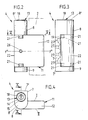
- a window frame 1 is assigned two window sashes 2. It is a turn / tilt window sash, which have the usual window locking device 3 and, in the area of the vertical hinge axis, are additionally provided with additional security at a maximum distance, in the form of a locking device 4 each.
- the vertical hinge axis is defined by an upper fitting 5 and a lower fitting 6.
- the lower fitting 6 forms together with a further fitting part 6 'at the same time the horizontal tilt axis, which are as far apart as possible with respect to the locking device 4 or locking devices 4, in the upper left or right corner of the window sash 2.
- the locking device 4 has a base plate 7 to be fastened to the window frame 1.
- the base plate is an elongated rectangular plan and forms end-protruding bearing eyes 8, 9 perpendicular to the plane of the base plate.
- the bearing eyes 8.9 take up a physical axis 10. This carries a securing plate 11 so that it can be folded.
- the folding plane lies transversely to the length of the base plate 7.
- the locking plate 11 is approximately square in plan.
- the side edge corresponds approximately to twice the width of the base plate 7, so that a sufficiently wide locking tab 12 in front of a sufficiently wide waxing lies.
- the locking tab 12 overlaps an edge portion of a frame leg of the window sash 2 in the locking position.
- a locking cylinder 13 serves as a locking means.
- the latter is designed as a pressure cylinder and is mounted in the upper, correspondingly axially elongated bearing eye 8 of the base plate 7 also cylindrical housing 15 of the lock cylinder 13 is matched.
- a grub screw 16 is used to fix the housing 15. The latter is inserted from the rear of the base plate 7, that is to say it is not accessible when the base plate is in the assembled state.
- the associated threaded bore bears the reference number 17.
- the geometric axis x-x of the locking cylinder 13 extends in parallel to the geometric axis y-y of the physical axis 10, which can also be referred to as an axle bolt.
- the top surface 8 'of the lock cylinder 13 carrying, axially elongated bearing eye 8 extends at right angles to the flat, the stop surface forming rear 7' of the base plate 7th
- the top surface 8 'of the bearing eye 8 carrying the locking cylinder 13 is oriented so that it slopes away from the base plate 7.
- the angle of inclination labeled Alpha is 30 °.
- the receptacle 14 is correspondingly oriented such that it lies perpendicular to the said head surface 8 ⁇ of the hub 8, that is to say no longer projects out above te spatial parallelism of the geometric axes xx and yy exists.
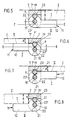
- this locking part 19 is a cylindrical locking bolt which passes through a central opening in the housing 13. The unlocked position results from Fig. 11, which shows the locking member in the spring-retracted position.
- the receptacle 14 For radially supported guidance of the locking part 19, the receptacle 14 continues into a guide bore 20 with a smaller cross section. The latter extends in the inner end region of the upper bearing eye 8.
- openings 11 are formed on the corresponding end face 22 'of the locking plate 11 for rotationally locking engagement of the locking member 19.
- the openings 21 extend in the area of a bearing hub 22 formed by the securing plate 11.
- the latter has an essentially cylindrical shape and extends over the entire axial width of said locking plate, thus extends from the bearing eye to the bearing eye.
- the openings 21 are realized diametrically opposite one another. Such openings 21 are congruently aligned and also lie on the end face 22 ⁇ of the bearing hub 22 facing the bearing eye 9. Accordingly, the securing plate 11 can optionally be set up for a right or left overlap of the window sash 2. Reference is made to FIGS. 5 and 8, where the corresponding change of sides can be seen while maintaining the distance A between the stop surface on the window sash side and the one broad surface I of the securing plate 11. To turn the securing plate 11 on the axis 10, the axis of the base plate 7 is releasably assigned. It can be seen in the lower bearing eye 9. The other bearing eye is closed at the top towards the hole.
- the problem of the different overhang dimension of the window sash 2 is also taken into account in terms of the abutment, that is, for example, a smaller dimension A 'than in FIG. 5.
- abutment that is, for example, a smaller dimension A 'than in FIG. 5.
- the other broad area II of the locking plate 11 lies on the visible side of the frame section of the window sash 2.
- This broad surface II runs tangentially into the cylindrical outer surface of the bearing hub 22. Both broad areas I, II extend parallel, the thickness of the locking flap thus created pens 12, as already indicated, is smaller than the diameter of the bearing hub 22.
- the ratio is approximately 1: 2.
- the longitudinal center plane EE of the locking plate 11 runs at a lateral distance z adjacent to the geometric axis 10, so that the illustrated alternative alternatives result using the created turning options, that is, the locking plate 11 both about a perpendicular to its plane and about it in-plane transverse central axis y ⁇ -y ⁇ . is reversible.
- a measure is taken in such a way that the locking part 19 of the locking cylinder 13 engages only part of its cross-section in the openings 21 and another part of its cross-section is embedded in a groove 23 of the base plate 7 in a virtually form-fitting manner.
- This groove 23 adjoins the guide bore 20 as a milling in the longitudinal direction of the base plate 7. It is realized as a U-shaped groove, but can also follow the course of the jacket of the cylindrical locking part 19. This leads to a both the horizontal joint F and the transverse, i.e. vertical joint F 'overlapping blocking zone.
- the axis 10 is secured by a cross screw 24.
- this cross screw it is a grub screw.
- the inner, lockable end has a conical shape and engages in a V-shaped annular groove 25 of the physical axis 10.
- the receptacle for the cross screw 24 is a cross hole which is open towards the base plate 7 in the locked position of the locking device 4 In this way, the safety device is hidden from view and also protected.
- two such transverse bores 26 are realized in the central region of the bearing hub 22. They lie diametrically opposite one another, in the same diametrical plane in which all openings 21 extend. The visible side remains empty.
- a measure that promotes the secure arrangement of the base plate 7 is that part of the retaining screw drill holes 27 of the base plate covered by the bearing hub 22 diverge. This means that these retaining screw boreholes have no orientation perpendicular to the plane of the base plate. This leads to a better anchoring hold of these retaining screws, so that they can withstand locking device 4 rough effects.
- the holding screw drill holes closer to the bearing eyes 8, 9 are expediently aligned in a divergent manner (cf. FIG. 3). These bear the reference symbol 27 '.
- the end on the insertion side is tapered.
Landscapes
- Engineering & Computer Science (AREA)
- Mechanical Engineering (AREA)
- Hinges (AREA)
- Massaging Devices (AREA)
- Lock And Its Accessories (AREA)
- Non-Silver Salt Photosensitive Materials And Non-Silver Salt Photography (AREA)
- Investigating Or Analysing Biological Materials (AREA)
- Centrifugal Separators (AREA)
Abstract
Description
- Die Erfindung bezieht sich auf eine Vorrichtung zur Verriegelung von Fenstern, Türen oder dergleichen, gemäß Oberbegriff des Patentanspruchs 1.
- Solche zusätzlich zur fenstereigenen Verriegelungseinrichtung einsetzbaren Verriegelungsvorrichtungen stellen ein weiteres wirksames Hindernis gegen unbefugte Öffnungsversuche dar; sie verzögern den Öffnungserfolg und erfordern überdies in aller Regel geräuschbringende Maßnahmen. Die bauliche und zuordnungstechnische Ausgestaltung solcher Verriegelungsvorrichtungen ist jedoch noch verbesserungsbedürftig.
- Aufgabe der Erfindung ist es daher, eine gattungsgemäße Vorrichtung zur Verriegelung von Fenstern, Türen oder dergleichen in herstellungstechnisch einfacher, montagegünstiger Weise so auszubilden, daß den in der Praxis unterschiedlichen Anschlagbedingungen entgegengekommen wird, also auch die Nachrüstung vereinfacht wird.
- Gelöst ist diese Aufgabe durch die im Anspruch 1 angegebene Erfindung.
- Die Unteransprüche sind vorteilhafte Weiterbildungen der erfindungsgemäßen Verriegelungsvorrichtung.
- Zufolge solcher Ausgestaltung ist eine gattungsgemäße Verriegelungsvorrichtung erhöhten Gebrauchswerts erzielt: Dieser liegt vor allem in der anschlagtechnisch optimierten Ausbildung begründet. Die Sicherungsplatte ist einfach umwendbar auf der Achse angeordnet. So läßt sich im Handumdrehen die Sicherungsplatte als rechts/ oder linksanschlagendes Element einrichten. Letzteres kann sogar vom verständigen Laien durchgeführt werden. Optimiert ist der anpaßbare Einsatz dadurch, daß die Sicherungsplatte, deren Längsmittelebene mit Abstand benachbart zur Achse verläuft, sowohl um eine senkrecht zu ihrer Ebene liegende als auch um ihre in der Ebene liegende Quermittelachse umwendbar ist. Hierdurch können sogar unterschiedliche Überstandsmaße des zu sichernden Flügelrahmens des Fensters bzw. der Tür erfaßt werden, neben der schon herausgestellten Rechts/Links-Verwendung. Zur Durchführung der entsprechenden Umstellung braucht dabei lediglich die in ihrer Funktionsstellung sicherbare Achse gezogen zu werden. Weiter wird vorgeschlagen, daß das Sperrteil des Schließzylinders in Öffnungen auf den Stirnflächen einer Lagernabe der Sicherungsplatte eintritt. Im Hinblick auf die Umwendbarkeit ist eine wendesymmetrische Ausrichtung dieser Öffnungen vorgenommen. Solche Öffnungen lassen sich in Nähe des Nabenrandes realisieren, so daß sich ein hebelgünstiger Abstand zur Achse ergibt. Da die Lagernabe von Hause aus ohnehin die größte Materialanhäufung bildet, sind die Öffnungen in einer stabilisatorisch günstigen Zone der Sicherungsplatte untergebracht. Dagegen ist der Schließzylinder in einem der an der Grundplatte vorstehenden Lageraugen der Achse angeordnet. Die Einverleibung des Schließzylinders in der Grundplatte beläßt den Schließzylinder am gewohnten Ort, was als handhabungsgünstiger empfunden wird gegenüber Lösungen, wie sie im Stand der Technik auftreten, die eine Zuordnung des Schließzylinders am beweglichen Teil, also der Sicherungsplatte der Verriegelungsvorrichtung vorsehen. Es muß für den einsteckenden Schlüssel dort auch in der Öffnungsstellung genügend Freiraum vorliegen. Besonders günstig ist es überdies, daß der Schließzylinder als Druckzylinder gestaltet ist, was dem axial orientierten Grundaufbau der Vorrichtung entgegenkommt. Hinsichtlich der Verriege lungsstabilität ist eine vorteilhafte Weiterbildung dadurch gefunden, daß das Sperrteil des Schließzylinders nur mit dem Teil seines Querschnitts in die Öffnungen eingreift und ein anderer Teil seines Querschnitts formpassend in eine Nut der Grundplatte eingebettet ist. Die sich zum Gesamtöffnungsquerschnitt ergänzende Öffnung ist so auf beide Grundbauteile der Verriegelungsvorrichtung verteilt. Der entsprechend fugenübergreifende Sperreingriff wirkt sich daher belastungsmäßig auf beide Teile aus, wobei es vorteilhaft ist, daß vom Sperreingriff her der rückwärtige Bereich durch die Bildung des Aufnahmeteils für den Schließzylinder ohnehin von Hause aus hoch stabil ist. Weiter wird vorgeschlagen, daß die Achse durch eine Querschraube gesichert ist, welche in einer zur Grundplatte hin offenen Querbohrung sitzt. Unter Berücksichtigung des wendesymmetrischen Aufbaues sind zwei Querbohrungen realisiert. Benutzt wird dabei die in Verriegelungsstellung nicht zugängliche. Das erhöht ebenfalls die Sicherheit einer solchen Verriegelungsvorrichtung, was anspruchsmäßig seinen Niederschlag in Anspruch 8 findet. Im Hinblick auf die Zugänglichkeit des Schließzylinders wirkt sich eine Weiterbildung dahingehend als vorteilhaft aus, daß die Kopffläche des den Schließzylinder tragenden Lagerauges von der Grundplatte wegweisend abfallend verläuft. Die Zylinderachse wird dadurch zugunsten einer Abhebung von der Befestigungsfläche weiter vorgezogen. Die Drückerbewegung des Schließzylinders liegt senkrecht zur Kopffläche, was auch neben der verbesserten Zugänglichkeit des Schlüssels auch noch den Eingriff in die Grundplatte verbessert, da sich der größere Eingriffsquerschnitt der Öffnung in Richtung des ortsfesten Bauteiles verlagert.
- Der Gegenstand der Erfindung ist nachstehend anhand eines zeichnerisch veranschaulichten Ausführungsbeispieles näher erläutert. Es zeigt:
- Fig. 1 zwei als Zusatzsicherung dienende Verriegelungsvorrichtungen an einem Doppelfenster, die jeweilige Wendeposition der Sicherungsplatte wiedergebend, in Verriegelungsstellung,
- Fig. 2 die Verriegelungsvorrichtung in Ansicht, in etwa natürlicher Größe, und zwar ebenfalls in Verriegelungsstellung,
- Fig. 3 die Seitenansicht von links hierzu,
- Fig. 4 die Draufsicht auf Fig. 2,
- Fig. 5-8 Schnitte gemäß Linie V-V in Fig. 2, unterschiedliche Anschlagsituationen wiedergebend,
- Fig. 9 die Rückansicht gegen die Grundplatte der Verriegelungsvorrichtung,
- Fig. 10 den Schnitt gemäß Linie X-X in Fig. 4,
- Fig. 11 einen der Fig. 10 entsprechenden Schnitt, jedoch in Entriegelungsstellung der Vorrichtung und
- Fig. 12 eine im Hinblick auf die Zuordnung des Schließzylinders variierte Ausgestaltung des Erfindungsgegenstandes.
- Einem Fensterrahmen 1 sind zwei Fensterflügel 2 zugeordnet. Es handelt sich um Dreh/Kipp-Fensterflügel, welche die übliche Fensterverriegelungsvorrichtung 3 aufweisen und darüber hinaus im Bereich der vertikalen Scharnierachse maximal beabstandet noch mit einer Zusatzsicherung versehen sind, dies in Form je einer Verriegelungsvorrichtung 4.
- Definiert ist die vertikale Scharnierachse durch einen oberen Beschlag 5 und einem unteren Beschlag 6.
- Der untere Beschlag 6 bildet zusammen mit einem weiteren Beschlagteil 6′ zugleich die horizontale Kippachse, auch der gegegenüber die Verriegelungsvorrichtung 4 bzw. Verriegelungsvorrichtungen 4 möglichst weit beabstandet liegen, und zwar in der oberen linken bzw. rechten Ecke des Fensterflügels 2.
- Für Türen ergibt sich eine ähnliche Zuordnungssituation, ohne jedoch auf das Mittel der zeichnerischen Wiedergabe zurückzugreifen.
- Die Verriegelungsvorrichtung besitzt 4 eine am Fensterrahmen 1 zu befestigende Grundplatte 7. Letztere ist langrechteckigen Grundrisses und bildet endseitig senkrecht zur Ebene der Grundplatte abstehende, also vorstehende Lageraugen 8,9 aus.
- Die Lageraugen 8,9 nehmen eine körperliche Achse 10 auf. Diese trägt klappbeweglich eine Sicherungsplatte 11. Die Klappebene liegt quer zur Längenerstreckung der Grundplatte 7.
- Die Sicherungsplatte 11 ist etwa quadratischen Grundrisses. Die Seitenkante entspricht etwa der doppelten Breite der Grundplatte 7, so daß bei entsprechend randnaher Verachsung ein genügend breiter Riegellappen 12 vor liegt. Der Riegellappen 12 übergreift in Verriegelungsstellung eine Randpartie eines Rahmenschenkels des Fensterflügels 2.
- Als Verriegelungsmittel dient ein Schließzylinder 13. Letzterer ist als Druckzylinder ausgebildet und lagert im oberen, entsprechend axial verlängerten Lagerauge 8 der Grundplatte 7. Die vom oberen Ende dieses Lagerauges 8 her eingearbeitete Aufnahme besteht aus einer zylindrischen Bohrung 14, deren Länge auf die axiale Länge des ebenfalls zylindrischen Gehäuses 15 des Schließzylinders 13 abgestimmt ist. Zur Festlegung des Gehäuses 15 dient eine Madenschraube 16. Letztere ist von der Rückseite der Grundplatte 7 her eingesetzt, also im montierten Zustand derselben nicht zugänglich. Die zugehörige Gewindebohrung trägt das Bezugszeichen 17.
- Beim Ausführungsbeispiel gemäß den Figuren 1 bis 11 erstreckt sich die geometrische Achse x-x des Schließzylinders 13 raumparallel zur geometrischen Achse y-y der körperlichen Achse 10, welche auch als Achsbolzen bezeichnet werden kann. Die Kopffläche 8′ des den Schließzylinder 13 tragenden, axial verlängerten Lagerauges 8 verläuft rechtwinklig zur ebenen, die Anschlagfläche bildenden Rückseite 7′ der Grundplatte 7.
- Beim Ausführungsbeispiel gemäß Fig. 12 ist dagegen eine Weiterbildung dahingehend vorgenommen, daß die dortige Kopffläche 8˝ des den Schließzylinder 13 tragenden Lagerauges 8 von der Grundplatte 7 wegweisend abfallend ausgerichtet ist. Der mit Alpha bezeichnete Neigungswinkel liegt bei 30°. Beim genannten Ausführungsbeispiel gemäß Fig. 12 ist die Aufnahme 14 entsprechend so ausgerichtet, daß sie senkrecht zur besagten Kopffläche 8˝ der Nabe 8 liegt, also nicht mehr die oben herausgestell te Raumparallelität der geometrischen Achsen x-x und y-y vorliegt. Vielmehr ergibt sich eine dem Winkel Alpha entsprechende Neigungslage der geometrischen Achse x′-x′ zur besagten Achse y-y mit der Konsequenz einer noch günstigeren Zugänglichkeit des Schließzylinders 13. Für die Bedienungshand und für das zielende Zuordnen des Schlüssels ergibt sich ein größerer Freiraum zur Anschlagebene. Der nicht dargestellte Schlüssel wird in den Schlüsselkanal eines zentral sowie anschlagbegrenzt im Gehäuse 15 gelagerten Zylinderkern 18 eingesteckt. Die Drückerbewegung des Schließzylinders 13, genauer des Zylinderkerns 18, erstreckt sich senkrecht zur pultförmig abfallenden Kopffläche 8˝.
- Über die besagte Drückerbewegung wird ein am inneren Ende des Zylinderkerns 18 des Schließzylinders 13 sitzendes Sperrteil 19 mit verlagert. Bezüglich dieses Sperrteils 19 handelt es sich um einen zylindrischen Sperrbolzen, welcher eine zentrale Durchbrechung des Gehäuses 13 geführt durchsetzt. Die entsperrte Stellung ergibt sich aus Fig. 11, welche das Sperrteil in federveranlaßt zurückgezogener Stellung wiedergibt.
- Zur radial abgestützten Führung des Sperrteiles 19 setzt sich die Aufnahme 14 in eine querschnittskleinere Führungsbohrung 20 fort. Letztere erstreckt sich im inneren Endbereich des oberen Lagerauges 8.
- Deckungsgleich zur besagten Bohrung 20 sind an der korrespondierenden Stirnfläche 22′ der Sicherungsplatte 11 Öffnungen 21 zum drehsperrenden Eingriff des Sperrteils 19 ausgebildet. Die Öffnungen 21 erstrecken sich im Bereich einer von der Sicherungsplatte 11 ausgebildeten Lagernabe 22. Letztere weist im wesentlichen zylindrische Gestalt auf und erstreckt sich über die gesamte axiale Breite der besagten Sicherungsplatte, reicht also von Lagerauge zu Lagerauge.
- Wie den Darstellungen in den Figuren 5 bis 8 entnehmbar, sind die Öffnungen 21 diametral einander gegenüberliegend realisiert. Deckungsgleich ausgerichtet liegen solche Öffnungen 21 auch auf der dem Lagerauge 9 zugewandten Stirnfläche 22˝ der Lagernabe 22. Demzufolge läßt sich die Sicherungsplatte 11 wahlweise auf einen Rechts- oder Linksübergriff des Fensterflügels 2 einrichten. Es wird auf die Figuren 5 und 8 verwiesen, wo unter Beibehaltung des Abstandes A zwischen fensterflügelseitiger Anschlagfläche und der einen Breitfläche I der Sicherungsplatte 11 der entsprechende Seitenwechsel erkennbar ist. Zum Umwenden der Sicherungsplatte 11 auf der Achse 10 ist die Achse der Grundplatte 7 lösbar zugeordnet. Sie läßt sich über das untere Lagerauge 9 entnehmen. Das andere Lagerauge ist bohrungsmäßig nach oben hin geschlossen.
- Neben dieser seitenvariierenden Maßnahme ist auch anschlagtechnisch das Problem des unterschiedlichen Überstandsmaßes der Fensterflügel 2 berücksichtigt, also hier beispielsweise ein kleineres Maß A′ als in Fig. 5 vorliegt. Unter Nutzung der raumsymmetrischen Anordnung der Öffnungen 21 läßt sich ein solch kleinerer Abstand A′ ebenfalls satt überfangen und sichern. Es wird auf die Figuren 6 und 7 verwiesen, und zwar auch hier unter Beibehaltung des Vorteils des Rechts/Links-Anschlages. Hierbei legt sich die andere Breitfläche II der Sperrplatte 11 auf die Sichtseite des Rahmenabschnitts des Fensterflügels 2 auf. Diese Breitfläche II läuft tangierend in die zylindrische Mantelfläche der Lagernabe 22 ein. Beide Breitflächen I,II erstrecken sich parallelverlaufend, wobei die Dicke des so geschaffenen Riegellap pens 12, wie schon angedeutet, geringer ist als der Durchmesser der Lagernabe 22. Das Verhältnis ist etwa 1 : 2.
- Bei dieser Konstellation verläuft die Längsmittelebene E-E der Sperrplatte 11 mit seitlichem Abstand z benachbart zur geometrischen Achse 10, so daß sich unter Nutzung der geschaffenen Wendemöglichkeiten die dargestellten Anschlagalternativen ergeben, indem also die Sicherungsplatte 11 sowohl um eine senkrecht zu ihrer Ebene liegende als auch um ihre in der Ebene liegende Quermittelachse y˝-y˝. umwendbar ist.
- Weiter ist, auch zur Erhöhung der Sperrsicherheit, eine Maßnahme dahingehend getroffen, daß das Sperrteil 19 des Schließzylinders 13 nur mit einem Teil seines Querschnitts in die Öffnungen 21 eingreift und ein anderer Teil seines Querschnitts praktisch formpassend in eine Nut 23 der Grundplatte 7 eingebettet ist. Diese Nut 23 schließt sich als in Längsrichtung der Grundplatte 7 ausgeführte Ausfräsung an die Führungsbohrung 20 an. Sie ist als U-förmige Nut realisiert, kann aber auch dem Mantelverlauf des zylindrischen Sperrteils 19 folgen. Das führt zu einer sowohl die horizontale Fuge F als auch die quer dazu liegende, also vertikale Fuge F′ übergreifenden Sperrzone.
- Die Achse 10 ist durch eine Querschraube 24 gesichert. Bezüglich dieser Querschraube handelt es sich um eine Madenschraube. Deren inneres, sperraktives Ende weist Kegelform auf und greift in eine V-förmige Ringnut 25 der körperlichen Achse 10 ein. Die Aufnahme für die Querschraube 24 ist eine in Sperrstellung der Verriegelungsvorrichtung 4 zur Grundplatte 7 hin offene Querboh rung 26. Das Sicherungsmittel ist auf diese Weise der Sicht entzogen und auch geschützt untergebracht.
- Der Wendbarkeit und dem variablen Einsatz Rechnung traend, sind zwei solcher Querbohrungen 26 im Mittelbereich der Lagernabe 22 realisiert. Sie liegen diametral einander gegenüber, und zwar in der gleichen Diametralebene, in der sich alle Öffnungen 21 erstrecken. Die sichtseitige bleibt jeweils leer.
- Eine die sichere Anordnung der Grundplatte 7 fördernde Maßnahme besteht darin, daß ein Teil der von der Lagernabe 22 abgedeckten Halteschrauben-Bohrlöcher 27 der Grundplatte divergiert. Das heißt, dieses Halteschrauben-Bohrlöcher weisen keine senkrecht zur Ebene der Grundplatte liegende Ausrichtung ein. Dies führt zu einem besseren Verankerungshalt dieser Halteschrauben, so daß sie Verriegelungseinrichtung 4 Grobeinwirkungen besser standhält. Zweckmäßig sind die den Lageraugen 8, 9 näherliegenden Halteschrauben-Bohrlöcher divergierend ausgerichtet (vergl. Fig. 3). Diese tragen das Bezugszeichen 27′.
- Zum erleichterten Einführen der körperlichen Achse 10 in die deckungsgleichen Bohrungen von Lageraugen 8,9 und Lagernabe 22 ist das einführseitige Ende kegelförmig zugespitzt.
- Nach Lösen der Querschraube 24 fällt die Achse infolge entsprechender Ausrichtung schwerkraftabhängig heraus.
- Alle in der Beschreibung erwähnten und in der Zeichnung dargestellten neuen Merkmale sind erfindungswesentlich, auch soweit sie in den Ansprüchen nicht ausdrücklich beansprucht sind.
- In die Offenbarung der Anmeldung wird hiermit der Offenbarungsinhalt der zugehörigen/beigeschlossenen Prioritätsunterlagen vollinhaltlich mit eingeschlossen.
Claims (10)
Priority Applications (1)
| Application Number | Priority Date | Filing Date | Title |
|---|---|---|---|
| AT90111322T ATE92997T1 (de) | 1989-06-30 | 1990-06-15 | Verriegelungsvorrichtung. |
Applications Claiming Priority (2)
| Application Number | Priority Date | Filing Date | Title |
|---|---|---|---|
| DE3921492 | 1989-06-30 | ||
| DE3921492A DE3921492C2 (de) | 1989-06-30 | 1989-06-30 | Verriegelungsvorrichtung |
Publications (3)
| Publication Number | Publication Date |
|---|---|
| EP0405252A2 true EP0405252A2 (de) | 1991-01-02 |
| EP0405252A3 EP0405252A3 (en) | 1991-08-21 |
| EP0405252B1 EP0405252B1 (de) | 1993-08-11 |
Family
ID=6383991
Family Applications (1)
| Application Number | Title | Priority Date | Filing Date |
|---|---|---|---|
| EP90111322A Expired - Lifetime EP0405252B1 (de) | 1989-06-30 | 1990-06-15 | Verriegelungsvorrichtung |
Country Status (3)
| Country | Link |
|---|---|
| EP (1) | EP0405252B1 (de) |
| AT (1) | ATE92997T1 (de) |
| DE (2) | DE3921492C2 (de) |
Cited By (2)
| Publication number | Priority date | Publication date | Assignee | Title |
|---|---|---|---|---|
| US6349576B2 (en) * | 1997-10-08 | 2002-02-26 | Allen-Stevens Corp. | Lockable sash assembly |
| WO2006003432A1 (en) * | 2004-07-06 | 2006-01-12 | Sure Locking Systems Limited | Lock mechanism |
Families Citing this family (4)
| Publication number | Priority date | Publication date | Assignee | Title |
|---|---|---|---|---|
| DE4321169A1 (de) * | 1993-06-25 | 1995-01-05 | Melchert Beschlaege | Vorrichtung zur Verriegelung von Fenstern, Türen oder dergleichen |
| DE29503112U1 (de) * | 1995-02-24 | 1995-06-01 | Ströter & Co., 42579 Heiligenhaus | Einbruchsicherung für Fenster |
| WO1997028336A1 (de) * | 1996-01-31 | 1997-08-07 | Oliver Berberich | Vorrichtung zur verriegelung eines zwischen zwei endstellungen um eine achse schwenkbaren, in verschlussstellung befindlichen bauteils zum verschliessen einer zugangsöffnung zu einem von wänden umschlossenen raum |
| DE19725102C2 (de) * | 1996-01-31 | 2003-02-13 | Oliver Berberich | Vorrichtung zur Verriegelung eines zwischen zwei Endstellungen bewegbaren, in Verschlußstellung befindlichen Bauteils zum Verschließen einer Zugangsöffnung zu einem von Wänden umschlossenen Raum |
Family Cites Families (8)
| Publication number | Priority date | Publication date | Assignee | Title |
|---|---|---|---|---|
| FR2468712A1 (fr) * | 1979-11-02 | 1981-05-08 | Adler Sa | Charniere a blocage selectif |
| US4322100A (en) * | 1979-12-03 | 1982-03-30 | Lyall A. McLennan | Abutment swivel doorstop |
| GB2098271A (en) * | 1981-05-09 | 1982-11-17 | Mallin Paul James | Locking device |
| DE8503363U1 (de) * | 1985-02-07 | 1985-05-15 | Franz Schneider Brakel GmbH & Co, 3492 Brakel | Sicherungsvorrichtung fuer fenster, tueren, klappen od. dgl. |
| DE8515524U1 (de) * | 1985-05-25 | 1985-08-29 | Fipke, Boris, 8044 Unterschleißheim | Sicherungeinrichtung für ein zu öffnendes Fenster od. dgl. |
| DE8804633U1 (de) * | 1988-04-08 | 1988-07-21 | Sondermann, Horst, 5620 Velbert | Sicherungseinrichtung für öffenbare Fenster od. dgl. |
| DE8812938U1 (de) * | 1988-10-14 | 1988-12-01 | W. Hautau GmbH, 3068 Helpsen | Beschlag zur Sicherung von beweglichen Flügeln für Fenster, Türen o.dgl. gegen Aufhebeln von außen |
| DE8901988U1 (de) * | 1989-02-20 | 1989-04-13 | Fipke, Boris, 8044 Unterschleißheim | Sicherungseinrichtung für Fenster |
-
1989
- 1989-06-30 DE DE3921492A patent/DE3921492C2/de not_active Expired - Fee Related
-
1990
- 1990-06-15 EP EP90111322A patent/EP0405252B1/de not_active Expired - Lifetime
- 1990-06-15 AT AT90111322T patent/ATE92997T1/de active
- 1990-06-15 DE DE9090111322T patent/DE59002279D1/de not_active Expired - Fee Related
Cited By (3)
| Publication number | Priority date | Publication date | Assignee | Title |
|---|---|---|---|---|
| US6349576B2 (en) * | 1997-10-08 | 2002-02-26 | Allen-Stevens Corp. | Lockable sash assembly |
| WO2006003432A1 (en) * | 2004-07-06 | 2006-01-12 | Sure Locking Systems Limited | Lock mechanism |
| US7836736B2 (en) | 2004-07-06 | 2010-11-23 | Sure Locking Systems Limited | Lock mechanism |
Also Published As
| Publication number | Publication date |
|---|---|
| EP0405252A3 (en) | 1991-08-21 |
| DE3921492A1 (de) | 1991-01-10 |
| EP0405252B1 (de) | 1993-08-11 |
| DE3921492C2 (de) | 1995-09-21 |
| ATE92997T1 (de) | 1993-08-15 |
| DE59002279D1 (de) | 1993-09-16 |
Similar Documents
| Publication | Publication Date | Title |
|---|---|---|
| EP0124838B1 (de) | Gelenk | |
| EP1235967B1 (de) | Band für türen, fenster oder dergleichen | |
| EP0010144A1 (de) | Flügelgelenkband für Fenster, Türen od. dgl. | |
| EP0405252B1 (de) | Verriegelungsvorrichtung | |
| DE2460402A1 (de) | Ausstellvorrichtung fuer kipp- drehfluegel von fenstern, tueren od. dgl. | |
| DE19522222C2 (de) | Scharnierbeschlag für ein Fenster, eine Tür od. dgl. | |
| EP0006440A2 (de) | Verstellbares Ecklager für Dreh-Kippflügel von Fenstern, Türen od. dgl. | |
| EP0861953B1 (de) | Betätigungshandhabe | |
| DE8805504U1 (de) | Scherenlager eines Dreh-Kipp-Beschlags | |
| EP0628688A2 (de) | Lagerteil eines Lagers für die wenigstens drehbare Lagerung eines Flügels, eines Fensters, einer Tür oder dergleichen | |
| EP0396209B1 (de) | Band für Türen, Fenster und dergleichen | |
| DE3901998A1 (de) | Eckverriegelungseinrichtung fuer fenster oder tueren | |
| DE8916155U1 (de) | Verriegelungsvorrichtung | |
| EP0704593B1 (de) | Dreh-Beschlag oder Dreh-Kipp-Beschlag von Fenster, Türen oder dergleichen mit verrastbarem Exzenterteil zum Einstellen einer horizontalen Falzluft und/oder eines Flügelanpressdrucks zwischen Festrahmen und/oder Flügelrahmen | |
| DE29615631U1 (de) | Sicherungseinrichtung | |
| DE4200868A1 (de) | Zusatz-schliesseinrichtung fuer fenster | |
| DE69614631T2 (de) | Scharnier für Tür, Fenster oder dergleichen | |
| EP2423426B1 (de) | Einbruchhemmender und/oder sprengwirkungshemmender Gebäudeabschluss | |
| DE3021178C2 (de) | Ecklageranordnung eines Drehkippbeschlags an einem Fenster o.dgl. | |
| DE2527348A1 (de) | Gelenkteil, insbesondere drehkipp- ecklager, fuer fenster, tueren o.dgl. | |
| DE4224619C2 (de) | Anschraubscharnier für Profilschienen | |
| EP0276379B1 (de) | Befestigungsvorrichtung für Beschlagteile | |
| DE3502655C2 (de) | Einbruchssicherung für mehrflügelige Fenster | |
| EP0924376A2 (de) | Aussenliegendes Lager für einen Schwingflügel | |
| DE9017458U1 (de) | Ausstellvorrichtung für ein Fenster, eine Tür o.dgl. |
Legal Events
| Date | Code | Title | Description |
|---|---|---|---|
| PUAI | Public reference made under article 153(3) epc to a published international application that has entered the european phase |
Free format text: ORIGINAL CODE: 0009012 |
|
| AK | Designated contracting states |
Kind code of ref document: A2 Designated state(s): AT BE CH DE LI LU NL |
|
| PUAL | Search report despatched |
Free format text: ORIGINAL CODE: 0009013 |
|
| AK | Designated contracting states |
Kind code of ref document: A3 Designated state(s): AT BE CH DE LI LU NL |
|
| 17P | Request for examination filed |
Effective date: 19911010 |
|
| 17Q | First examination report despatched |
Effective date: 19921106 |
|
| GRAA | (expected) grant |
Free format text: ORIGINAL CODE: 0009210 |
|
| AK | Designated contracting states |
Kind code of ref document: B1 Designated state(s): AT BE CH DE LI LU NL |
|
| REF | Corresponds to: |
Ref document number: 92997 Country of ref document: AT Date of ref document: 19930815 Kind code of ref document: T |
|
| REF | Corresponds to: |
Ref document number: 59002279 Country of ref document: DE Date of ref document: 19930916 |
|
| PLBE | No opposition filed within time limit |
Free format text: ORIGINAL CODE: 0009261 |
|
| STAA | Information on the status of an ep patent application or granted ep patent |
Free format text: STATUS: NO OPPOSITION FILED WITHIN TIME LIMIT |
|
| EPTA | Lu: last paid annual fee | ||
| 26N | No opposition filed | ||
| PGFP | Annual fee paid to national office [announced via postgrant information from national office to epo] |
Ref country code: CH Payment date: 19970516 Year of fee payment: 8 Ref country code: AT Payment date: 19970516 Year of fee payment: 8 |
|
| PGFP | Annual fee paid to national office [announced via postgrant information from national office to epo] |
Ref country code: NL Payment date: 19970630 Year of fee payment: 8 |
|
| PGFP | Annual fee paid to national office [announced via postgrant information from national office to epo] |
Ref country code: LU Payment date: 19970702 Year of fee payment: 8 |
|
| PG25 | Lapsed in a contracting state [announced via postgrant information from national office to epo] |
Ref country code: LU Free format text: LAPSE BECAUSE OF NON-PAYMENT OF DUE FEES Effective date: 19980615 Ref country code: AT Free format text: LAPSE BECAUSE OF NON-PAYMENT OF DUE FEES Effective date: 19980615 |
|
| PG25 | Lapsed in a contracting state [announced via postgrant information from national office to epo] |
Ref country code: LI Free format text: LAPSE BECAUSE OF NON-PAYMENT OF DUE FEES Effective date: 19980630 Ref country code: CH Free format text: LAPSE BECAUSE OF NON-PAYMENT OF DUE FEES Effective date: 19980630 |
|
| PG25 | Lapsed in a contracting state [announced via postgrant information from national office to epo] |
Ref country code: NL Free format text: LAPSE BECAUSE OF NON-PAYMENT OF DUE FEES Effective date: 19990101 |
|
| REG | Reference to a national code |
Ref country code: CH Ref legal event code: PL |
|
| NLV4 | Nl: lapsed or anulled due to non-payment of the annual fee |
Effective date: 19990101 |
|
| PGFP | Annual fee paid to national office [announced via postgrant information from national office to epo] |
Ref country code: BE Payment date: 19990528 Year of fee payment: 10 |
|
| PGFP | Annual fee paid to national office [announced via postgrant information from national office to epo] |
Ref country code: DE Payment date: 19990607 Year of fee payment: 10 |
|
| PG25 | Lapsed in a contracting state [announced via postgrant information from national office to epo] |
Ref country code: BE Free format text: LAPSE BECAUSE OF NON-PAYMENT OF DUE FEES Effective date: 20000630 |
|
| BERE | Be: lapsed |
Owner name: MELCHERT BESCHLAGE G.M.B.H. & CO. K.G. Effective date: 20000630 |
|
| PG25 | Lapsed in a contracting state [announced via postgrant information from national office to epo] |
Ref country code: DE Free format text: LAPSE BECAUSE OF NON-PAYMENT OF DUE FEES Effective date: 20010403 |