EP0405252A2 - Verrou - Google Patents
Verrou Download PDFInfo
- Publication number
- EP0405252A2 EP0405252A2 EP90111322A EP90111322A EP0405252A2 EP 0405252 A2 EP0405252 A2 EP 0405252A2 EP 90111322 A EP90111322 A EP 90111322A EP 90111322 A EP90111322 A EP 90111322A EP 0405252 A2 EP0405252 A2 EP 0405252A2
- Authority
- EP
- European Patent Office
- Prior art keywords
- locking
- axis
- base plate
- particular according
- cylinder
- Prior art date
- Legal status (The legal status is an assumption and is not a legal conclusion. Google has not performed a legal analysis and makes no representation as to the accuracy of the status listed.)
- Granted
Links
- 210000003128 head Anatomy 0.000 claims description 5
- 230000002441 reversible effect Effects 0.000 claims description 3
- 238000009420 retrofitting Methods 0.000 abstract description 2
- 238000010276 construction Methods 0.000 abstract 1
- 238000011161 development Methods 0.000 description 4
- 230000018109 developmental process Effects 0.000 description 4
- 230000002349 favourable effect Effects 0.000 description 2
- 238000003780 insertion Methods 0.000 description 2
- 230000037431 insertion Effects 0.000 description 2
- 241001295925 Gegenes Species 0.000 description 1
- 238000009825 accumulation Methods 0.000 description 1
- 238000004873 anchoring Methods 0.000 description 1
- 230000015572 biosynthetic process Effects 0.000 description 1
- 230000000903 blocking effect Effects 0.000 description 1
- 230000000694 effects Effects 0.000 description 1
- 238000005516 engineering process Methods 0.000 description 1
- 230000005484 gravity Effects 0.000 description 1
- 238000010348 incorporation Methods 0.000 description 1
- 238000003801 milling Methods 0.000 description 1
- 230000000087 stabilizing effect Effects 0.000 description 1
- 238000004018 waxing Methods 0.000 description 1
Images



Classifications
-
- E—FIXED CONSTRUCTIONS
- E05—LOCKS; KEYS; WINDOW OR DOOR FITTINGS; SAFES
- E05C—BOLTS OR FASTENING DEVICES FOR WINGS, SPECIALLY FOR DOORS OR WINDOWS
- E05C3/00—Fastening devices with bolts moving pivotally or rotatively
- E05C3/02—Fastening devices with bolts moving pivotally or rotatively without latching action
- E05C3/04—Fastening devices with bolts moving pivotally or rotatively without latching action with operating handle or equivalent member rigid with the bolt
- E05C3/047—Fastening devices with bolts moving pivotally or rotatively without latching action with operating handle or equivalent member rigid with the bolt rotating about an axis parallel to the surface on which the fastener is mounted
- E05C3/048—Fastening devices with bolts moving pivotally or rotatively without latching action with operating handle or equivalent member rigid with the bolt rotating about an axis parallel to the surface on which the fastener is mounted parallel to the wing edge
-
- E—FIXED CONSTRUCTIONS
- E05—LOCKS; KEYS; WINDOW OR DOOR FITTINGS; SAFES
- E05B—LOCKS; ACCESSORIES THEREFOR; HANDCUFFS
- E05B63/00—Locks or fastenings with special structural characteristics
- E05B63/0052—Locks mounted on the "frame" cooperating with means on the "wing"
Definitions
- the invention relates to a device for locking windows, doors or the like, according to the preamble of claim 1.
- Such locking devices which can be used in addition to the window-specific locking device, represent a further effective obstacle against unauthorized attempts to open them; they delay the opening success and, moreover, generally require noise-reducing measures.
- the structural and assignment design of such locking devices is still in need of improvement.
- the object of the invention is therefore to design a generic device for locking windows, doors or the like in a technically simple, easy-to-assemble manner in such a way that the different stop conditions in practice are accommodated, thus also simplifying the retrofitting.
- a generic locking device of increased utility value is achieved: This is primarily due to the design optimized in terms of attachment technology.
- the locking plate is easily reversible on the axis. In this way, the locking plate can be set up as a right or left-hinged element in no time at all. The latter can even be done by the knowledgeable layperson.
- the adaptable insert is optimized in that the securing plate, the longitudinal center plane of which runs adjacent to the axis at a distance, can be turned both about a transverse central axis lying perpendicular to its plane and about its transverse central axis. In this way, different overhang dimensions of the sash frame of the window or door to be secured can be detected, in addition to the right / left use already mentioned.
- the locking part of the locking cylinder enters openings on the end faces of a bearing hub of the locking plate.
- these openings are aligned in a symmetrical manner.
- Such openings can be realized in the vicinity of the hub edge, so that there is a leverage distance to the axis.
- the bearing hub forms the largest material accumulation anyway, the openings are housed in a stabilizing zone of the securing plate.
- the locking cylinder is arranged in one of the bearing eyes of the axle projecting from the base plate.
- the locking cylinder is designed as a pressure cylinder, which accommodates the axially oriented basic structure of the device.
- Stability is an advantageous development found that the locking part of the lock cylinder engages only with part of its cross-section in the openings and another part of its cross-section is embedded in a groove in the base plate.
- the opening which complements the overall opening cross section is thus distributed over both basic components of the locking device.
- the corresponding joint-overlapping locking action therefore affects the load on both parts, it being advantageous that the rear area is already highly stable from the start due to the formation of the receiving part for the locking cylinder.
- the axis be secured by a cross screw which is seated in a cross hole open towards the base plate. Taking into account the turn-symmetrical structure, two cross holes are made. The one that is not accessible in the locked position is used. This also increases the security of such a locking device, which is reflected in claim 8.
- the accessibility of the locking cylinder a further development has the advantage that the head surface of the bearing eye that supports the locking cylinder slopes away from the base plate.
- the cylinder axis is thereby further advanced in favor of a lift off the mounting surface.
- the pusher movement of the locking cylinder is perpendicular to the head surface, which, in addition to the improved accessibility of the key, also improves the engagement in the base plate, since the larger engagement cross-section of the opening shifts in the direction of the stationary component.
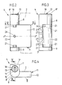
- a window frame 1 is assigned two window sashes 2. It is a turn / tilt window sash, which have the usual window locking device 3 and, in the area of the vertical hinge axis, are additionally provided with additional security at a maximum distance, in the form of a locking device 4 each.
- the vertical hinge axis is defined by an upper fitting 5 and a lower fitting 6.
- the lower fitting 6 forms together with a further fitting part 6 'at the same time the horizontal tilt axis, which are as far apart as possible with respect to the locking device 4 or locking devices 4, in the upper left or right corner of the window sash 2.
- the locking device 4 has a base plate 7 to be fastened to the window frame 1.
- the base plate is an elongated rectangular plan and forms end-protruding bearing eyes 8, 9 perpendicular to the plane of the base plate.
- the bearing eyes 8.9 take up a physical axis 10. This carries a securing plate 11 so that it can be folded.
- the folding plane lies transversely to the length of the base plate 7.
- the locking plate 11 is approximately square in plan.
- the side edge corresponds approximately to twice the width of the base plate 7, so that a sufficiently wide locking tab 12 in front of a sufficiently wide waxing lies.
- the locking tab 12 overlaps an edge portion of a frame leg of the window sash 2 in the locking position.
- a locking cylinder 13 serves as a locking means.
- the latter is designed as a pressure cylinder and is mounted in the upper, correspondingly axially elongated bearing eye 8 of the base plate 7 also cylindrical housing 15 of the lock cylinder 13 is matched.
- a grub screw 16 is used to fix the housing 15. The latter is inserted from the rear of the base plate 7, that is to say it is not accessible when the base plate is in the assembled state.
- the associated threaded bore bears the reference number 17.
- the geometric axis x-x of the locking cylinder 13 extends in parallel to the geometric axis y-y of the physical axis 10, which can also be referred to as an axle bolt.
- the top surface 8 'of the lock cylinder 13 carrying, axially elongated bearing eye 8 extends at right angles to the flat, the stop surface forming rear 7' of the base plate 7th
- the top surface 8 'of the bearing eye 8 carrying the locking cylinder 13 is oriented so that it slopes away from the base plate 7.
- the angle of inclination labeled Alpha is 30 °.
- the receptacle 14 is correspondingly oriented such that it lies perpendicular to the said head surface 8 ⁇ of the hub 8, that is to say no longer projects out above te spatial parallelism of the geometric axes xx and yy exists.
- this locking part 19 is a cylindrical locking bolt which passes through a central opening in the housing 13. The unlocked position results from Fig. 11, which shows the locking member in the spring-retracted position.
- the receptacle 14 For radially supported guidance of the locking part 19, the receptacle 14 continues into a guide bore 20 with a smaller cross section. The latter extends in the inner end region of the upper bearing eye 8.
- openings 11 are formed on the corresponding end face 22 'of the locking plate 11 for rotationally locking engagement of the locking member 19.
- the openings 21 extend in the area of a bearing hub 22 formed by the securing plate 11.
- the latter has an essentially cylindrical shape and extends over the entire axial width of said locking plate, thus extends from the bearing eye to the bearing eye.
- the openings 21 are realized diametrically opposite one another. Such openings 21 are congruently aligned and also lie on the end face 22 ⁇ of the bearing hub 22 facing the bearing eye 9. Accordingly, the securing plate 11 can optionally be set up for a right or left overlap of the window sash 2. Reference is made to FIGS. 5 and 8, where the corresponding change of sides can be seen while maintaining the distance A between the stop surface on the window sash side and the one broad surface I of the securing plate 11. To turn the securing plate 11 on the axis 10, the axis of the base plate 7 is releasably assigned. It can be seen in the lower bearing eye 9. The other bearing eye is closed at the top towards the hole.
- the problem of the different overhang dimension of the window sash 2 is also taken into account in terms of the abutment, that is, for example, a smaller dimension A 'than in FIG. 5.
- abutment that is, for example, a smaller dimension A 'than in FIG. 5.
- the other broad area II of the locking plate 11 lies on the visible side of the frame section of the window sash 2.
- This broad surface II runs tangentially into the cylindrical outer surface of the bearing hub 22. Both broad areas I, II extend parallel, the thickness of the locking flap thus created pens 12, as already indicated, is smaller than the diameter of the bearing hub 22.
- the ratio is approximately 1: 2.
- the longitudinal center plane EE of the locking plate 11 runs at a lateral distance z adjacent to the geometric axis 10, so that the illustrated alternative alternatives result using the created turning options, that is, the locking plate 11 both about a perpendicular to its plane and about it in-plane transverse central axis y ⁇ -y ⁇ . is reversible.
- a measure is taken in such a way that the locking part 19 of the locking cylinder 13 engages only part of its cross-section in the openings 21 and another part of its cross-section is embedded in a groove 23 of the base plate 7 in a virtually form-fitting manner.
- This groove 23 adjoins the guide bore 20 as a milling in the longitudinal direction of the base plate 7. It is realized as a U-shaped groove, but can also follow the course of the jacket of the cylindrical locking part 19. This leads to a both the horizontal joint F and the transverse, i.e. vertical joint F 'overlapping blocking zone.
- the axis 10 is secured by a cross screw 24.
- this cross screw it is a grub screw.
- the inner, lockable end has a conical shape and engages in a V-shaped annular groove 25 of the physical axis 10.
- the receptacle for the cross screw 24 is a cross hole which is open towards the base plate 7 in the locked position of the locking device 4 In this way, the safety device is hidden from view and also protected.
- two such transverse bores 26 are realized in the central region of the bearing hub 22. They lie diametrically opposite one another, in the same diametrical plane in which all openings 21 extend. The visible side remains empty.
- a measure that promotes the secure arrangement of the base plate 7 is that part of the retaining screw drill holes 27 of the base plate covered by the bearing hub 22 diverge. This means that these retaining screw boreholes have no orientation perpendicular to the plane of the base plate. This leads to a better anchoring hold of these retaining screws, so that they can withstand locking device 4 rough effects.
- the holding screw drill holes closer to the bearing eyes 8, 9 are expediently aligned in a divergent manner (cf. FIG. 3). These bear the reference symbol 27 '.
- the end on the insertion side is tapered.
Landscapes
- Engineering & Computer Science (AREA)
- Mechanical Engineering (AREA)
- Hinges (AREA)
- Massaging Devices (AREA)
- Lock And Its Accessories (AREA)
- Non-Silver Salt Photosensitive Materials And Non-Silver Salt Photography (AREA)
- Investigating Or Analysing Biological Materials (AREA)
- Centrifugal Separators (AREA)
Priority Applications (1)
| Application Number | Priority Date | Filing Date | Title |
|---|---|---|---|
| AT90111322T ATE92997T1 (de) | 1989-06-30 | 1990-06-15 | Verriegelungsvorrichtung. |
Applications Claiming Priority (2)
| Application Number | Priority Date | Filing Date | Title |
|---|---|---|---|
| DE3921492 | 1989-06-30 | ||
| DE3921492A DE3921492C2 (de) | 1989-06-30 | 1989-06-30 | Verriegelungsvorrichtung |
Publications (3)
| Publication Number | Publication Date |
|---|---|
| EP0405252A2 true EP0405252A2 (fr) | 1991-01-02 |
| EP0405252A3 EP0405252A3 (en) | 1991-08-21 |
| EP0405252B1 EP0405252B1 (fr) | 1993-08-11 |
Family
ID=6383991
Family Applications (1)
| Application Number | Title | Priority Date | Filing Date |
|---|---|---|---|
| EP90111322A Expired - Lifetime EP0405252B1 (fr) | 1989-06-30 | 1990-06-15 | Verrou |
Country Status (3)
| Country | Link |
|---|---|
| EP (1) | EP0405252B1 (fr) |
| AT (1) | ATE92997T1 (fr) |
| DE (2) | DE3921492C2 (fr) |
Cited By (2)
| Publication number | Priority date | Publication date | Assignee | Title |
|---|---|---|---|---|
| US6349576B2 (en) * | 1997-10-08 | 2002-02-26 | Allen-Stevens Corp. | Lockable sash assembly |
| WO2006003432A1 (fr) * | 2004-07-06 | 2006-01-12 | Sure Locking Systems Limited | Mécanisme de verrouillage |
Families Citing this family (4)
| Publication number | Priority date | Publication date | Assignee | Title |
|---|---|---|---|---|
| DE4321169A1 (de) * | 1993-06-25 | 1995-01-05 | Melchert Beschlaege | Vorrichtung zur Verriegelung von Fenstern, Türen oder dergleichen |
| DE29503112U1 (de) * | 1995-02-24 | 1995-06-01 | Ströter & Co., 42579 Heiligenhaus | Einbruchsicherung für Fenster |
| WO1997028336A1 (fr) * | 1996-01-31 | 1997-08-07 | Oliver Berberich | Dispositif servant a verrouiller un composant pivotant entre deux positions extremes autour d'un axe et se trouvant en position fermee pour obstruer l'ouverture d'acces a un espace entoure par des murs |
| DE19725102C2 (de) * | 1996-01-31 | 2003-02-13 | Oliver Berberich | Vorrichtung zur Verriegelung eines zwischen zwei Endstellungen bewegbaren, in Verschlußstellung befindlichen Bauteils zum Verschließen einer Zugangsöffnung zu einem von Wänden umschlossenen Raum |
Family Cites Families (8)
| Publication number | Priority date | Publication date | Assignee | Title |
|---|---|---|---|---|
| FR2468712A1 (fr) * | 1979-11-02 | 1981-05-08 | Adler Sa | Charniere a blocage selectif |
| US4322100A (en) * | 1979-12-03 | 1982-03-30 | Lyall A. McLennan | Abutment swivel doorstop |
| GB2098271A (en) * | 1981-05-09 | 1982-11-17 | Mallin Paul James | Locking device |
| DE8503363U1 (de) * | 1985-02-07 | 1985-05-15 | Franz Schneider Brakel GmbH & Co, 3492 Brakel | Sicherungsvorrichtung fuer fenster, tueren, klappen od. dgl. |
| DE8515524U1 (de) * | 1985-05-25 | 1985-08-29 | Fipke, Boris, 8044 Unterschleißheim | Sicherungeinrichtung für ein zu öffnendes Fenster od. dgl. |
| DE8804633U1 (de) * | 1988-04-08 | 1988-07-21 | Sondermann, Horst, 5620 Velbert | Sicherungseinrichtung für öffenbare Fenster od. dgl. |
| DE8812938U1 (de) * | 1988-10-14 | 1988-12-01 | W. Hautau GmbH, 3068 Helpsen | Beschlag zur Sicherung von beweglichen Flügeln für Fenster, Türen o.dgl. gegen Aufhebeln von außen |
| DE8901988U1 (de) * | 1989-02-20 | 1989-04-13 | Fipke, Boris, 8044 Unterschleißheim | Sicherungseinrichtung für Fenster |
-
1989
- 1989-06-30 DE DE3921492A patent/DE3921492C2/de not_active Expired - Fee Related
-
1990
- 1990-06-15 EP EP90111322A patent/EP0405252B1/fr not_active Expired - Lifetime
- 1990-06-15 AT AT90111322T patent/ATE92997T1/de active
- 1990-06-15 DE DE9090111322T patent/DE59002279D1/de not_active Expired - Fee Related
Cited By (3)
| Publication number | Priority date | Publication date | Assignee | Title |
|---|---|---|---|---|
| US6349576B2 (en) * | 1997-10-08 | 2002-02-26 | Allen-Stevens Corp. | Lockable sash assembly |
| WO2006003432A1 (fr) * | 2004-07-06 | 2006-01-12 | Sure Locking Systems Limited | Mécanisme de verrouillage |
| US7836736B2 (en) | 2004-07-06 | 2010-11-23 | Sure Locking Systems Limited | Lock mechanism |
Also Published As
| Publication number | Publication date |
|---|---|
| EP0405252A3 (en) | 1991-08-21 |
| DE3921492A1 (de) | 1991-01-10 |
| EP0405252B1 (fr) | 1993-08-11 |
| DE3921492C2 (de) | 1995-09-21 |
| ATE92997T1 (de) | 1993-08-15 |
| DE59002279D1 (de) | 1993-09-16 |
Similar Documents
| Publication | Publication Date | Title |
|---|---|---|
| EP0124838B1 (fr) | Articulation | |
| EP1235967B1 (fr) | Bande pour portes, fenetres et similaires | |
| EP0010144A1 (fr) | Ferrure d'articulation pour fenêtres, portes ou analogues | |
| EP0405252B1 (fr) | Verrou | |
| DE2460402A1 (de) | Ausstellvorrichtung fuer kipp- drehfluegel von fenstern, tueren od. dgl. | |
| DE19522222C2 (de) | Scharnierbeschlag für ein Fenster, eine Tür od. dgl. | |
| EP0006440A2 (fr) | Palier d'angle ajustable pour vantaux oscillo-battants de fenêtres, portes ou similaires | |
| EP0861953B1 (fr) | Poignée de manoeuvre | |
| DE8805504U1 (de) | Scherenlager eines Dreh-Kipp-Beschlags | |
| EP0628688A2 (fr) | Elément de palier d'un support pour le support au moins pivotant d'une aile, d'une fenêtre, d'une porte ou similaire | |
| EP0396209B1 (fr) | Charnière pour portes, fenêtres ou similaires | |
| DE3901998A1 (de) | Eckverriegelungseinrichtung fuer fenster oder tueren | |
| DE8916155U1 (de) | Verriegelungsvorrichtung | |
| EP0704593B1 (fr) | Ferrure pour battant pivotant, ou pivotant et basculant, de fenêtres, portes ou similaires avec pièce excentrique verrouillable pour regler la feuillure verticale et/ou la force de pression entre le vantail et le cadre fixe | |
| DE29615631U1 (de) | Sicherungseinrichtung | |
| DE4200868A1 (de) | Zusatz-schliesseinrichtung fuer fenster | |
| DE69614631T2 (de) | Scharnier für Tür, Fenster oder dergleichen | |
| EP2423426B1 (fr) | Fermeture de bâtiment réduisant l'effet d'explosion et/ou d'implosion | |
| DE3021178C2 (de) | Ecklageranordnung eines Drehkippbeschlags an einem Fenster o.dgl. | |
| DE2527348A1 (de) | Gelenkteil, insbesondere drehkipp- ecklager, fuer fenster, tueren o.dgl. | |
| DE4224619C2 (de) | Anschraubscharnier für Profilschienen | |
| EP0276379B1 (fr) | Dispositif de fixation pour armatures | |
| DE3502655C2 (de) | Einbruchssicherung für mehrflügelige Fenster | |
| EP0924376A2 (fr) | Palier externe pour vantail basculant | |
| DE9017458U1 (de) | Ausstellvorrichtung für ein Fenster, eine Tür o.dgl. |
Legal Events
| Date | Code | Title | Description |
|---|---|---|---|
| PUAI | Public reference made under article 153(3) epc to a published international application that has entered the european phase |
Free format text: ORIGINAL CODE: 0009012 |
|
| AK | Designated contracting states |
Kind code of ref document: A2 Designated state(s): AT BE CH DE LI LU NL |
|
| PUAL | Search report despatched |
Free format text: ORIGINAL CODE: 0009013 |
|
| AK | Designated contracting states |
Kind code of ref document: A3 Designated state(s): AT BE CH DE LI LU NL |
|
| 17P | Request for examination filed |
Effective date: 19911010 |
|
| 17Q | First examination report despatched |
Effective date: 19921106 |
|
| GRAA | (expected) grant |
Free format text: ORIGINAL CODE: 0009210 |
|
| AK | Designated contracting states |
Kind code of ref document: B1 Designated state(s): AT BE CH DE LI LU NL |
|
| REF | Corresponds to: |
Ref document number: 92997 Country of ref document: AT Date of ref document: 19930815 Kind code of ref document: T |
|
| REF | Corresponds to: |
Ref document number: 59002279 Country of ref document: DE Date of ref document: 19930916 |
|
| PLBE | No opposition filed within time limit |
Free format text: ORIGINAL CODE: 0009261 |
|
| STAA | Information on the status of an ep patent application or granted ep patent |
Free format text: STATUS: NO OPPOSITION FILED WITHIN TIME LIMIT |
|
| EPTA | Lu: last paid annual fee | ||
| 26N | No opposition filed | ||
| PGFP | Annual fee paid to national office [announced via postgrant information from national office to epo] |
Ref country code: CH Payment date: 19970516 Year of fee payment: 8 Ref country code: AT Payment date: 19970516 Year of fee payment: 8 |
|
| PGFP | Annual fee paid to national office [announced via postgrant information from national office to epo] |
Ref country code: NL Payment date: 19970630 Year of fee payment: 8 |
|
| PGFP | Annual fee paid to national office [announced via postgrant information from national office to epo] |
Ref country code: LU Payment date: 19970702 Year of fee payment: 8 |
|
| PG25 | Lapsed in a contracting state [announced via postgrant information from national office to epo] |
Ref country code: LU Free format text: LAPSE BECAUSE OF NON-PAYMENT OF DUE FEES Effective date: 19980615 Ref country code: AT Free format text: LAPSE BECAUSE OF NON-PAYMENT OF DUE FEES Effective date: 19980615 |
|
| PG25 | Lapsed in a contracting state [announced via postgrant information from national office to epo] |
Ref country code: LI Free format text: LAPSE BECAUSE OF NON-PAYMENT OF DUE FEES Effective date: 19980630 Ref country code: CH Free format text: LAPSE BECAUSE OF NON-PAYMENT OF DUE FEES Effective date: 19980630 |
|
| PG25 | Lapsed in a contracting state [announced via postgrant information from national office to epo] |
Ref country code: NL Free format text: LAPSE BECAUSE OF NON-PAYMENT OF DUE FEES Effective date: 19990101 |
|
| REG | Reference to a national code |
Ref country code: CH Ref legal event code: PL |
|
| NLV4 | Nl: lapsed or anulled due to non-payment of the annual fee |
Effective date: 19990101 |
|
| PGFP | Annual fee paid to national office [announced via postgrant information from national office to epo] |
Ref country code: BE Payment date: 19990528 Year of fee payment: 10 |
|
| PGFP | Annual fee paid to national office [announced via postgrant information from national office to epo] |
Ref country code: DE Payment date: 19990607 Year of fee payment: 10 |
|
| PG25 | Lapsed in a contracting state [announced via postgrant information from national office to epo] |
Ref country code: BE Free format text: LAPSE BECAUSE OF NON-PAYMENT OF DUE FEES Effective date: 20000630 |
|
| BERE | Be: lapsed |
Owner name: MELCHERT BESCHLAGE G.M.B.H. & CO. K.G. Effective date: 20000630 |
|
| PG25 | Lapsed in a contracting state [announced via postgrant information from national office to epo] |
Ref country code: DE Free format text: LAPSE BECAUSE OF NON-PAYMENT OF DUE FEES Effective date: 20010403 |