EP0405290A1 - Procédé et installation pour l'épuration des composés nocifs contenus dans les effluents gazeux de combustion - Google Patents
Procédé et installation pour l'épuration des composés nocifs contenus dans les effluents gazeux de combustion Download PDFInfo
- Publication number
- EP0405290A1 EP0405290A1 EP90111510A EP90111510A EP0405290A1 EP 0405290 A1 EP0405290 A1 EP 0405290A1 EP 90111510 A EP90111510 A EP 90111510A EP 90111510 A EP90111510 A EP 90111510A EP 0405290 A1 EP0405290 A1 EP 0405290A1
- Authority
- EP
- European Patent Office
- Prior art keywords
- flue gas
- substances
- carbon
- reactor
- separated
- Prior art date
- Legal status (The legal status is an assumption and is not a legal conclusion. Google has not performed a legal analysis and makes no representation as to the accuracy of the status listed.)
- Withdrawn
Links
Images
Classifications
-
- B—PERFORMING OPERATIONS; TRANSPORTING
- B01—PHYSICAL OR CHEMICAL PROCESSES OR APPARATUS IN GENERAL
- B01D—SEPARATION
- B01D53/00—Separation of gases or vapours; Recovering vapours of volatile solvents from gases; Chemical or biological purification of waste gases, e.g. engine exhaust gases, smoke, fumes, flue gases, aerosols
- B01D53/34—Chemical or biological purification of waste gases
- B01D53/46—Removing components of defined structure
- B01D53/48—Sulfur compounds
- B01D53/50—Sulfur oxides
- B01D53/501—Sulfur oxides by treating the gases with a solution or a suspension of an alkali or earth-alkali or ammonium compound
-
- B—PERFORMING OPERATIONS; TRANSPORTING
- B01—PHYSICAL OR CHEMICAL PROCESSES OR APPARATUS IN GENERAL
- B01D—SEPARATION
- B01D53/00—Separation of gases or vapours; Recovering vapours of volatile solvents from gases; Chemical or biological purification of waste gases, e.g. engine exhaust gases, smoke, fumes, flue gases, aerosols
- B01D53/34—Chemical or biological purification of waste gases
- B01D53/46—Removing components of defined structure
- B01D53/48—Sulfur compounds
- B01D53/50—Sulfur oxides
- B01D53/508—Sulfur oxides by treating the gases with solids
-
- B—PERFORMING OPERATIONS; TRANSPORTING
- B01—PHYSICAL OR CHEMICAL PROCESSES OR APPARATUS IN GENERAL
- B01D—SEPARATION
- B01D53/00—Separation of gases or vapours; Recovering vapours of volatile solvents from gases; Chemical or biological purification of waste gases, e.g. engine exhaust gases, smoke, fumes, flue gases, aerosols
- B01D53/34—Chemical or biological purification of waste gases
- B01D53/46—Removing components of defined structure
- B01D53/68—Halogens or halogen compounds
- B01D53/70—Organic halogen compounds
Definitions
- the invention relates to a method and a device for cleaning pollutant-laden flue gas from incineration plants, in particular waste incineration plants, the fly ash possibly present in the flue gas being separated and the flue gas being passed through a first reaction area in which it is mixed with basic, generally calcium-containing substances, e.g. B. calcium hydroxide (Ca (OH) 2) and / or limestone (CaCO3) and / or calcium oxide (CaO) in finely divided form wet, quasi-dry or dry is brought into intimate contact, pollutants, for. B.
- basic, generally calcium-containing substances e.g.
- basic, generally calcium-containing substances e.g.
- B. calcium hydroxide (Ca (OH) 2) and / or limestone (CaCO3) and / or calcium oxide (CaO) in finely divided form wet, quasi-dry or dry is brought into intimate contact, pollutants, for. B.
- the invention is based on a method and a device of the type described in the introduction.
- the object of the invention is to improve it over the subject of the application of EP-A-0 283 721 / 88102412.9 in such a way that smaller amounts of coke or other carbon-containing substances are sufficient to achieve the desired cleaning effect.
- the aim is to keep the amount of coke or the like loaded with the pollutants, which has to be deposited or otherwise disposed of, to be as low as possible.
- the invention proposes that the contact between the flue gas to be cleaned and the carbon-containing substances takes place within the second reaction area in the entrained flow and then at least the carbon-containing substances are separated from the flue gas and divided into at least two fractions and at least parts of the coarser ones Fraction in the combustion chamber and / or be returned to one of the reaction areas.
- Flue gas cleaning using carbon-containing substances in the entrained flow process offers considerable advantages over the use of fixed beds.
- So dust-like solids for example coke
- can be used in the entrained flow method which have a grain size of z. B. have a maximum of about 0.5 mm. This results in more favorable conditions with regard to grain diffusion, which lead to a higher speed with which the individual grain is loaded with the pollutants.
- This higher loading speed is also further promoted by the fact that there is a greater relative speed between the flue gas and the individual carbon particles in the entrained flow method. This greater relative speed is primarily due to the fact that the flue gas has a significantly higher speed when using the entrained flow method than when flowing through a fixed bed.
- the speed when using the entrained current method is of the order of z. B. 10 - 20 m / sec. Because of these conditions, it is possible when using the entrained-flow process to make do with much smaller aggregates and with much smaller amounts of coke than with the fixed-bed process. In addition, the subdivision of the solids separated from the flue gas behind the second reaction area into a coarser and a finer fraction and the recirculation of the coarser Frak tion for better utilization of the carbonaceous adsorbent.
- the pollutants By returning the coarser fraction to the combustion chamber and burning it, the pollutants, insofar as they are not already separated in the first reaction area, are deposited in a high concentration on the grains of the finer fraction, with the result that, owing to the high levels thus achieved Loading of the fine fraction the amount of coke loaded with the pollutants, which has to be disposed of, for example to be placed in a landfill, remains relatively small.
- the temperature of the flue gas during the removal of the pollutants will be around 100-200 ° C.
- the procedure can be such that the subdivision of at least the carbon-containing substances into at least two fractions is carried out by carrying out the deposition of these substances from the flue gas depending on their particle size.
- This type of process control has the advantage that it is not necessary to additionally subject the solid substances separated from the flue gas to any sorting processes in order to divide them into the desired fractions.
- the basic substances which are fed to the first reaction area or the reaction products of these basic substances can also be passed through the second reaction area, so that they coexist with at least some of the carbon-containing substances be separated from the flue gas stream. Due to the fact that the basic substances predominantly have a significantly smaller grain size than the carbon-containing substances, the basic substances in this case are largely removed from the flue gas with the fine-grained fraction of the carbon-containing substances are so that the coarse fraction of the solids separated after the second reaction region essentially contains carbon-containing substances, for example coke. In general, at least when using a dry or quasi-dry method in the first reaction area, the grain size of the basic substances will not or only slightly exceed an order of magnitude of 5-10 ⁇ m.
- the components of the coarser fraction of the in Flow direction behind the second reaction area separated substances are at least partially returned to the second reaction area.
- a return of at least a part of the existing fraction to the first reaction area will be considered in particular when the basic substances or their reaction products are only are separated from the flue gas after the second reaction area.
- the invention further relates to a device for cleaning pollutant-containing flue gas from incinerators with an electrostatic precipitator for separating fly ash, a first reactor region arranged downstream in the flow direction, which is charged with wet or dry basic substances in finely divided form, and one downstream in the flow direction of the flue gas arranged second reactor area, which is charged with a carbon-containing substance, in particular coke.
- the invention proposes to design the second reactor area as entrained flow reactor and to arrange at least two separators one behind the other in the flow direction of the flue gas behind the second reactor area, in which the solid substances in the flue gas are separated depending on their particle size in such a way that first the coarser particles and then the finer particles are separated from the flue gas.
- the separator for the coarser particles can be designed as a cyclone, the separator for the finer particles as an electrostatic filter or a cloth filter.
- the latter has the advantage that a layer of the deposited fine substances forms on the filter fabric, through which the flue gas must flow, so that this layer forms an additional filter that binds any remaining constituents of pollutants in the flue gas.
- the two reactor areas can also be combined into one structural unit.
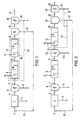
- a boiler 1 is provided in which waste 2 is burned. This creates coarse ash 3 and flue gas 4.
- the coarse ash 3 is removed from the boiler separately from the flue gas.
- the flue gas 4, which contains many pollutants, is first passed through an electrostatic filter 5, in which fly ash 6 is separated.
- the dedusted flue gas 7, optionally with the interposition of heat exchangers, which are not shown in the drawing, is fed to a first reactor region 8, in which calcium-containing substances, e.g. B. calcium hydroxide (Ca (OH) 2) or limestone (CaCO3) or calcium oxide (CaO) alone or in a mixture in the flue gas 7 can be entered.
- calcium-containing substances e.g. B. calcium hydroxide (Ca (OH) 2) or limestone (CaCO3) or calcium oxide (CaO) alone or in a mixture in the flue gas 7 can be entered.
- These basic substances 9 can be wet or dry, at least in finely divided form, sprayed or blown into the reactor 8 and swirled therein with the dedusted flue gas 7.
- 8 internals 10 are present in the reactor area, which lead to a multiple deflection of the flue gas 7.
- this mixture of flue gas 11 and the solid substances described above enters a second reactor region 12 to which a dusty, carbon-containing substance 13, for example coke, is fed dry. This can be done in such a way that the dust-like carbon-containing substance 13 is blown into the flue gas 11.
- the second reactor area 12 is also provided with internals 14 through which the flue gas 11 is deflected several times. This serves an intimate mixing of flue gas 11 and carbon-containing substances 13 and also to increase the relative speed between flue gas and the particles of the solid carbon-containing substances.
- the second reactor area 12 there is an adsorptive addition of the remaining constituents of SO2, HCl and HF to the carbon-containing substances 13.
- organic compounds, in particular dioxins and furans, and heavy metals are also adsorptively attached to the carbon-containing substance 13 in the reactor region 12.
- a mixture 15 consequently leaves the second reactor region 12, which consists of the largely cleaned flue gas 11 and the solid substances, which are the carbon-containing substances 13 loaded with pollutants and the reaction products of the basic, generally calcium-containing substance 9 and residues of this basic substance 9, which have not been implemented.
- This mixture 15 is fed into a cyclone separator 16, in which the coarser particles of the solids are separated from the flue gas 15 and are led out of the cyclone 16 as coarser fraction 17.
- the largely pollutant-free flue gas 18, which is freed from the larger solid particles 17, but which still contains portions of fine, dust-like particles, is passed into an electrostatic filter or a cloth filter 19, in which the fine solid particles are separated from the flue gas 18 he follows. These fine solid particles are removed from the filter 19 as a fine solid fraction 20.
- the largely cleaned and dedusted flue gas 21 is released into the atmosphere via a chimney.
- the fine dust 20 can be placed in a landfill. However, it has proven to be expedient to return part of the fine fraction 20 in order to achieve the greatest possible loading, in particular of the carbon-containing substance with pollutants. 1, a part 34 of the fine fraction 20 can be returned to the first reactor area 8, where it can be blown into the first reactor area 8 together with the fresh, basic substance.
- the coarse fraction 17 separated from the flue gas 15 in the cyclone 16 is returned to the combustion chamber 1 in the exemplary embodiment according to FIG. 1 and burned together with the waste 2.
- the two reactor regions 8 and 12 can be designed in the same or a similar manner, so that they can also be combined to form a structural unit 35, as is indicated by dash-dotted lines in FIG. 1 of the drawing.
- a fine sieve can be arranged below the cyclone separator 16, with which the fine particles are still sieved out from the coarse fraction 17 in order to be deposited or possibly also to be returned. This sieve is not shown in the drawing.
- the flue gas 11 first passes through an electrostatic filter 22 after leaving the first reactor region 8.
- the basic substances or their reaction products 23 are separated out in this and, for example, placed in a landfill. That of the products 23 too At least largely freed flue gas 24 then enters the second reactor area 12, in which, as already described in connection with FIG. 1, it is treated with a carbon-containing substance 13 which is blown into the second reactor area 12.
- a mixture 25 of largely cleaned flue gas and carbon-containing substance loaded with the pollutants leaves the reactor 12.
- This mixture 25 is introduced into the cyclone separator 26, in which the coarser particles 27 of the solids are removed from the flue gas.
- the fraction 27 formed from these coarser particles is at least predominantly returned to the boiler 1 and burned there together with the waste 2.
- the flue gas 29 cleaned of the coarse-grained solids 27, which still contains the fine-grained solids, is fed into the electrostatic filter or cloth filter 28, in which the fine particles 30 are separated from the flue gas 29. At least part of the fine fraction 30 is deposited. Another part is returned via a branch line 31 and added to the carbon-containing substance 13, which is blown into the second reactor region 12. This measure also serves to achieve the greatest possible loading of pollutants from fraction 30 from the fine particles.
- the coarser fraction 27 is at least predominantly returned to the boiler 1 and burned there with the garbage 2.
Landscapes
- Engineering & Computer Science (AREA)
- Chemical & Material Sciences (AREA)
- Health & Medical Sciences (AREA)
- Biomedical Technology (AREA)
- Environmental & Geological Engineering (AREA)
- Analytical Chemistry (AREA)
- General Chemical & Material Sciences (AREA)
- Oil, Petroleum & Natural Gas (AREA)
- Chemical Kinetics & Catalysis (AREA)
- Treating Waste Gases (AREA)
- Chimneys And Flues (AREA)
- Separation Of Gases By Adsorption (AREA)
Applications Claiming Priority (2)
| Application Number | Priority Date | Filing Date | Title |
|---|---|---|---|
| DE19893921578 DE3921578A1 (de) | 1989-06-30 | 1989-06-30 | Verfahren zur reinigung von rauchgas aus verbrennungsanlagen |
| DE3921578 | 1989-06-30 |
Publications (1)
| Publication Number | Publication Date |
|---|---|
| EP0405290A1 true EP0405290A1 (fr) | 1991-01-02 |
Family
ID=6384051
Family Applications (1)
| Application Number | Title | Priority Date | Filing Date |
|---|---|---|---|
| EP90111510A Withdrawn EP0405290A1 (fr) | 1989-06-30 | 1990-06-19 | Procédé et installation pour l'épuration des composés nocifs contenus dans les effluents gazeux de combustion |
Country Status (4)
| Country | Link |
|---|---|
| EP (1) | EP0405290A1 (fr) |
| JP (1) | JPH0352622A (fr) |
| DD (1) | DD296217A5 (fr) |
| DE (1) | DE3921578A1 (fr) |
Cited By (14)
| Publication number | Priority date | Publication date | Assignee | Title |
|---|---|---|---|---|
| DE4120277A1 (de) * | 1991-06-19 | 1992-12-24 | Krupp Polysius Ag | Verfahren und vorrichtung zum reinigen von abgasen aus ofenanlagen |
| EP0565728A4 (fr) * | 1991-09-05 | 1994-02-02 | Daikin Industries, Ltd. | |
| EP0628341A1 (fr) * | 1993-06-10 | 1994-12-14 | Beco Engineering Company | Elimination des métaux lourds de gaz de fumées des installations d'incinération |
| DE4339072A1 (de) * | 1993-11-16 | 1995-05-18 | Bischoff Gasreinigung | Verfahren zur Abtrennung von Quecksilber und Quecksilberverbindungen aus heißem, Schwefelverbindungen enthaltendem Abgas |
| DE4344113A1 (de) * | 1993-12-23 | 1995-06-29 | Metallgesellschaft Ag | Verfahren zur Reinigung von Abgasen der Abfallverbrennung |
| WO1996015845A1 (fr) * | 1994-11-18 | 1996-05-30 | Steag Aktiengesellschaft | Procede et dispositif de lavage d'effluents gazeux de combustion |
| EP0748766A1 (fr) * | 1995-06-16 | 1996-12-18 | Rheinische Kalksteinwerke GmbH. | Granulate à base de carbonates des métaux alcalino-terreux contenant des composées ad- ou absorbants |
| US5607654A (en) * | 1991-06-10 | 1997-03-04 | Beco Engineering Company | Method for minimizing environmental release of toxic compounds in the incineration of wastes |
| WO1998025690A1 (fr) * | 1996-12-13 | 1998-06-18 | Thyssen Stahl Ag | Procede permettant de diminuer la concentration en pcdd et/ou en pcdf dans des gaz brules |
| US5895520A (en) * | 1996-05-18 | 1999-04-20 | Metallgesellschaft Aktiengesellschaft | Method of separating noxious substances from exhaust gases |
| US6090355A (en) * | 1995-11-13 | 2000-07-18 | Steag Aktiengesellschaft | Method and device for cleaning flue gases from furnaces |
| RU2216388C1 (ru) * | 2002-10-17 | 2003-11-20 | Государственное унитарное предприятие "Федеральный научно-производственный центр "Прибор" | Устройство для сорбционной нейтрализации газов |
| CN100409924C (zh) * | 2006-06-13 | 2008-08-13 | 冯之军 | 一种燃煤锅炉烟气净化装置及方法 |
| US8167975B2 (en) | 2007-04-13 | 2012-05-01 | Babcock-Hitachi Kabushiki Kaisha | Exhaust gas purifying method and apparatus |
Families Citing this family (10)
| Publication number | Priority date | Publication date | Assignee | Title |
|---|---|---|---|---|
| JPH07114922B2 (ja) * | 1990-06-13 | 1995-12-13 | 日立造船株式会社 | 排ガス処理方法 |
| DE4104180C1 (en) * | 1991-02-12 | 1992-06-17 | Metallgesellschaft Ag, 6000 Frankfurt, De | Removing acidic gases from combustion gases - comprises feeding gases through vortex reactor contg. dispersed ground chalk, passing hot gases through heat exchanger and electrostatic particle separator |
| JP2560931B2 (ja) * | 1991-07-25 | 1996-12-04 | 日本鋼管株式会社 | 排ガス中の有害物質の除去方法 |
| DE4207879C2 (de) * | 1992-02-10 | 1999-02-25 | Johannes Prof Dr Rer N Gartzen | Verfahren mindestens zur Verminderung des Schwefelgehaltes der Rauchgase von Feuerungsanlagen mit Kohlefeuerung |
| JP3101181B2 (ja) * | 1994-08-17 | 2000-10-23 | 奥多摩工業株式会社 | 排ガス処理剤及び排ガス処理方法 |
| DE19849022A1 (de) * | 1998-10-23 | 2000-04-27 | Asea Brown Boveri | Verfahren zur Verminderung von Korrosion in Feuerungsanlagen, insbesondere Müllverbrennungsanlagen |
| JP4674897B2 (ja) * | 2005-06-24 | 2011-04-20 | 岡部株式会社 | 型枠支持具及びそれに用いる型枠支持具用座体 |
| US10888836B2 (en) | 2014-07-25 | 2021-01-12 | Chemical and Metal Technologies LLC | Extraction of target materials using CZTS sorbent |
| JP7470488B2 (ja) * | 2017-05-26 | 2024-04-18 | ケミカル アンド メタル テクノロジーズ リミテッド ライアビリティ カンパニー | 流動床装置、及び排出物制御方法 |
| CN113310059B (zh) * | 2021-06-03 | 2023-08-15 | 苏州安杰源环境科技有限公司 | 一种rto处理方式 |
Citations (4)
| Publication number | Priority date | Publication date | Assignee | Title |
|---|---|---|---|---|
| DE2904312A1 (de) * | 1979-02-05 | 1980-08-07 | Bergwerksverband Gmbh | Verfahren zur trockenen, adsorptiven hcl-abscheidung |
| EP0193135A2 (fr) * | 1985-03-01 | 1986-09-03 | Hugo Petersen Ges. für verfahrenstechn. Anlagenbau mbH & Co KG | Procédé pour enlever le dioxyde de soufre et les oxydes d'azote d'un gaz de rejet |
| EP0253563A1 (fr) * | 1986-07-16 | 1988-01-20 | Niro A/S | Procédé pour éliminer la vapeur de mercure et/ou la vapeur de composés organiques nuisibles et/ou les oxydes d'azote des gaz de rejet d'une installation d'incinération |
| EP0283721A2 (fr) * | 1987-02-26 | 1988-09-28 | Rheinbraun Aktiengesellschaft | Procédé pour enlever des matériaux nocifs de gaz |
Family Cites Families (3)
| Publication number | Priority date | Publication date | Assignee | Title |
|---|---|---|---|---|
| DE3318880A1 (de) * | 1981-11-24 | 1985-01-17 | Hölter, Heinz, Dipl.-Ing., 4390 Gladbeck | Quasi trockene rauchgasentschwefelung mit mehrstufiger chemisorptionsmittelnutzung - vorzugsweise kalknutzung |
| DE3610942A1 (de) * | 1985-11-26 | 1987-08-13 | Lothar Dipl Ing Mueller | Verfahren zur simultanen schadstoffbeseitigung aus rauchgasen und reaktor zur durchfuehrung des verfahrens |
| DE3616310A1 (de) * | 1986-05-14 | 1987-12-03 | Walter Kaercher | Verfahren und vorrichtung zum entfernen von stickoxiden aus rauchgasen durch selektive trockenadsorption |
-
1989
- 1989-06-30 DE DE19893921578 patent/DE3921578A1/de not_active Withdrawn
-
1990
- 1990-06-19 EP EP90111510A patent/EP0405290A1/fr not_active Withdrawn
- 1990-06-29 DD DD34228090A patent/DD296217A5/de not_active IP Right Cessation
- 1990-06-30 JP JP2174345A patent/JPH0352622A/ja active Pending
Patent Citations (4)
| Publication number | Priority date | Publication date | Assignee | Title |
|---|---|---|---|---|
| DE2904312A1 (de) * | 1979-02-05 | 1980-08-07 | Bergwerksverband Gmbh | Verfahren zur trockenen, adsorptiven hcl-abscheidung |
| EP0193135A2 (fr) * | 1985-03-01 | 1986-09-03 | Hugo Petersen Ges. für verfahrenstechn. Anlagenbau mbH & Co KG | Procédé pour enlever le dioxyde de soufre et les oxydes d'azote d'un gaz de rejet |
| EP0253563A1 (fr) * | 1986-07-16 | 1988-01-20 | Niro A/S | Procédé pour éliminer la vapeur de mercure et/ou la vapeur de composés organiques nuisibles et/ou les oxydes d'azote des gaz de rejet d'une installation d'incinération |
| EP0283721A2 (fr) * | 1987-02-26 | 1988-09-28 | Rheinbraun Aktiengesellschaft | Procédé pour enlever des matériaux nocifs de gaz |
Cited By (17)
| Publication number | Priority date | Publication date | Assignee | Title |
|---|---|---|---|---|
| US5607654A (en) * | 1991-06-10 | 1997-03-04 | Beco Engineering Company | Method for minimizing environmental release of toxic compounds in the incineration of wastes |
| DE4120277A1 (de) * | 1991-06-19 | 1992-12-24 | Krupp Polysius Ag | Verfahren und vorrichtung zum reinigen von abgasen aus ofenanlagen |
| EP0565728A4 (fr) * | 1991-09-05 | 1994-02-02 | Daikin Industries, Ltd. | |
| US5439659A (en) * | 1991-09-05 | 1995-08-08 | Daikin Industries, Ltd. | Method for treating exhaust gas and an apparatus therefor |
| EP0628341A1 (fr) * | 1993-06-10 | 1994-12-14 | Beco Engineering Company | Elimination des métaux lourds de gaz de fumées des installations d'incinération |
| DE4339072A1 (de) * | 1993-11-16 | 1995-05-18 | Bischoff Gasreinigung | Verfahren zur Abtrennung von Quecksilber und Quecksilberverbindungen aus heißem, Schwefelverbindungen enthaltendem Abgas |
| DE4344113A1 (de) * | 1993-12-23 | 1995-06-29 | Metallgesellschaft Ag | Verfahren zur Reinigung von Abgasen der Abfallverbrennung |
| WO1996015845A1 (fr) * | 1994-11-18 | 1996-05-30 | Steag Aktiengesellschaft | Procede et dispositif de lavage d'effluents gazeux de combustion |
| US5811066A (en) * | 1994-11-18 | 1998-09-22 | Steag Aktiengesellschaft | Method and device for scrubbing flue gases |
| EP0748766A1 (fr) * | 1995-06-16 | 1996-12-18 | Rheinische Kalksteinwerke GmbH. | Granulate à base de carbonates des métaux alcalino-terreux contenant des composées ad- ou absorbants |
| US6090355A (en) * | 1995-11-13 | 2000-07-18 | Steag Aktiengesellschaft | Method and device for cleaning flue gases from furnaces |
| US5895520A (en) * | 1996-05-18 | 1999-04-20 | Metallgesellschaft Aktiengesellschaft | Method of separating noxious substances from exhaust gases |
| WO1998025690A1 (fr) * | 1996-12-13 | 1998-06-18 | Thyssen Stahl Ag | Procede permettant de diminuer la concentration en pcdd et/ou en pcdf dans des gaz brules |
| RU2216388C1 (ru) * | 2002-10-17 | 2003-11-20 | Государственное унитарное предприятие "Федеральный научно-производственный центр "Прибор" | Устройство для сорбционной нейтрализации газов |
| CN100409924C (zh) * | 2006-06-13 | 2008-08-13 | 冯之军 | 一种燃煤锅炉烟气净化装置及方法 |
| US8167975B2 (en) | 2007-04-13 | 2012-05-01 | Babcock-Hitachi Kabushiki Kaisha | Exhaust gas purifying method and apparatus |
| DE112008000984B4 (de) * | 2007-04-13 | 2021-01-07 | Mitsubishi Power, Ltd. | Abgasreinigungsverfahren und Vorrichtung |
Also Published As
| Publication number | Publication date |
|---|---|
| DE3921578A1 (de) | 1991-01-03 |
| JPH0352622A (ja) | 1991-03-06 |
| DD296217A5 (de) | 1991-11-28 |
Similar Documents
| Publication | Publication Date | Title |
|---|---|---|
| DD296217A5 (de) | Verfahren zur reinigung von rauchgasen aus verbrennungsanlagen | |
| DE19517863C2 (de) | Verfahren zur trockenen Entschwefelung eines Verbrennungsabgases | |
| EP0172588B1 (fr) | Procédé de séparation de NOx et de SO2 de gaz brûlés | |
| EP0105547A1 (fr) | Procédé pour séparer des matières nocives de gaz de fumée | |
| EP0479350A1 (fr) | Procédé de séparation de métaux lourds et de dioxines de gaz brulés | |
| EP1275430A2 (fr) | Procédé et appareil pour purifier des gases de combustion | |
| EP0682558B1 (fr) | Agent d'epuration a sec de gaz de combustion | |
| EP0283721B1 (fr) | Procédé pour enlever des matériaux nocifs de gaz | |
| EP0697239B1 (fr) | Procédé et dispositif pour la séparation d'hydrocarbures polycycliques et polyhalogénés, en particulier de dioxines et furanes d'un gaz de fumée d'un procédé de frittage | |
| EP0592025B1 (fr) | Procédé pour séparer des dioxines et furanes halogénés des gaz d'échappement de dispositifs de combustion | |
| EP0228111B2 (fr) | Procédé pour l'élimination des substances nocives dans des gaz d'échappement | |
| DE19841513A1 (de) | Verfahren zur Reinigung von Abgasen aus Verbrennungsanlagen | |
| EP1025894B1 (fr) | Procédé ainsi que l'adsorbant pour la purification à sec de gaz d'échappement | |
| EP0196481A1 (fr) | Procédé et dispositif pour séparer des composés polluants d'un courant de gaz | |
| EP0677319B1 (fr) | Procédé et dispositif pour éliminer les dioxines of furanes d'un gaz d'échappement d'un procédé de frittage | |
| EP0594232A1 (fr) | Procédé pour la réduction catalytique d'oxydes d'azote dans les gaz de combustion | |
| DE19623981A1 (de) | Verfahren zum Entfernen schädlicher Inhaltsstoffe aus Abgasen von Sinteranlagen | |
| EP0476727B1 (fr) | Procédé pour éviter la formation d'hydrocarbures aromatiques condensées et des dioxines dans des installations de combustion | |
| DE19940683B4 (de) | Verfahren zur trockenen Reinigung von Abgasen aus Sinteranlagen, Hüttenwerken oder sekundär metallurgischen Schmelzanlagen sowie staubförmiges Sorbens zur trockenen Reinigung solcher Abgase | |
| DE19638584C2 (de) | Verfahren zur Abscheidung von Staub aus einem staubhaltigen und wasserdampfhaltigen Abgas in einem filtrierenden Abscheider | |
| EP0919274B1 (fr) | Procédé pour la purification de gaz d'échappement des installations de combustion | |
| DE4344112C2 (de) | Verfahren zur Steuerung der Sorptionsleistung eines Filtrationsabscheiders | |
| EP0908220A1 (fr) | Procédé d'utilisation de catalysateur usé | |
| WO1998025690A1 (fr) | Procede permettant de diminuer la concentration en pcdd et/ou en pcdf dans des gaz brules | |
| DD264859A1 (de) | Verfahren zur abscheidung von schadgasen |
Legal Events
| Date | Code | Title | Description |
|---|---|---|---|
| PUAI | Public reference made under article 153(3) epc to a published international application that has entered the european phase |
Free format text: ORIGINAL CODE: 0009012 |
|
| AK | Designated contracting states |
Kind code of ref document: A1 Designated state(s): AT BE CH DE DK ES FR GB IT LI NL SE |
|
| 17P | Request for examination filed |
Effective date: 19910625 |
|
| STAA | Information on the status of an ep patent application or granted ep patent |
Free format text: STATUS: THE APPLICATION IS DEEMED TO BE WITHDRAWN |
|
| 18D | Application deemed to be withdrawn |
Effective date: 19921231 |