EP0405357B1 - Miniaturfrankiermaschine - Google Patents
Miniaturfrankiermaschine Download PDFInfo
- Publication number
- EP0405357B1 EP0405357B1 EP19900111868 EP90111868A EP0405357B1 EP 0405357 B1 EP0405357 B1 EP 0405357B1 EP 19900111868 EP19900111868 EP 19900111868 EP 90111868 A EP90111868 A EP 90111868A EP 0405357 B1 EP0405357 B1 EP 0405357B1
- Authority
- EP
- European Patent Office
- Prior art keywords
- machine according
- module
- print head
- printing
- franking machine
- Prior art date
- Legal status (The legal status is an assumption and is not a legal conclusion. Google has not performed a legal analysis and makes no representation as to the accuracy of the status listed.)
- Expired - Lifetime
Links
- 238000007639 printing Methods 0.000 claims description 101
- 230000015654 memory Effects 0.000 claims description 23
- 238000005303 weighing Methods 0.000 claims description 10
- 230000008878 coupling Effects 0.000 claims description 7
- 238000010168 coupling process Methods 0.000 claims description 7
- 238000005859 coupling reaction Methods 0.000 claims description 7
- 239000011159 matrix material Substances 0.000 claims description 6
- 230000000295 complement effect Effects 0.000 claims description 5
- 238000003780 insertion Methods 0.000 claims description 3
- 230000037431 insertion Effects 0.000 claims description 3
- 230000004044 response Effects 0.000 claims description 3
- 230000001737 promoting effect Effects 0.000 claims 10
- 230000001133 acceleration Effects 0.000 claims 1
- 230000000977 initiatory effect Effects 0.000 claims 1
- 230000000750 progressive effect Effects 0.000 claims 1
- 238000006073 displacement reaction Methods 0.000 description 8
- 238000000034 method Methods 0.000 description 8
- 238000004364 calculation method Methods 0.000 description 3
- 238000001514 detection method Methods 0.000 description 3
- 235000010603 pastilles Nutrition 0.000 description 3
- 230000000717 retained effect Effects 0.000 description 3
- 238000010276 construction Methods 0.000 description 2
- 238000010586 diagram Methods 0.000 description 2
- 238000007641 inkjet printing Methods 0.000 description 2
- 238000012423 maintenance Methods 0.000 description 2
- 230000008569 process Effects 0.000 description 2
- 238000012546 transfer Methods 0.000 description 2
- 230000001960 triggered effect Effects 0.000 description 2
- 241000861223 Issus Species 0.000 description 1
- 240000008042 Zea mays Species 0.000 description 1
- 238000004590 computer program Methods 0.000 description 1
- 230000003247 decreasing effect Effects 0.000 description 1
- 238000001914 filtration Methods 0.000 description 1
- 238000005259 measurement Methods 0.000 description 1
- 230000007246 mechanism Effects 0.000 description 1
- 238000012986 modification Methods 0.000 description 1
- 230000004048 modification Effects 0.000 description 1
- 238000011017 operating method Methods 0.000 description 1
- 230000002093 peripheral effect Effects 0.000 description 1
- 238000012545 processing Methods 0.000 description 1
- 230000003252 repetitive effect Effects 0.000 description 1
- 230000002441 reversible effect Effects 0.000 description 1
Images




Classifications
-
- G—PHYSICS
- G07—CHECKING-DEVICES
- G07B—TICKET-ISSUING APPARATUS; FARE-REGISTERING APPARATUS; FRANKING APPARATUS
- G07B17/00—Franking apparatus
- G07B17/00185—Details internally of apparatus in a franking system, e.g. franking machine at customer or apparatus at post office
- G07B17/00193—Constructional details of apparatus in a franking system
-
- G—PHYSICS
- G07—CHECKING-DEVICES
- G07B—TICKET-ISSUING APPARATUS; FARE-REGISTERING APPARATUS; FRANKING APPARATUS
- G07B17/00—Franking apparatus
- G07B17/00016—Relations between apparatus, e.g. franking machine at customer or apparatus at post office, in a franking system
- G07B17/0008—Communication details outside or between apparatus
-
- G—PHYSICS
- G07—CHECKING-DEVICES
- G07B—TICKET-ISSUING APPARATUS; FARE-REGISTERING APPARATUS; FRANKING APPARATUS
- G07B17/00—Franking apparatus
- G07B17/00016—Relations between apparatus, e.g. franking machine at customer or apparatus at post office, in a franking system
- G07B17/0008—Communication details outside or between apparatus
- G07B2017/00153—Communication details outside or between apparatus for sending information
- G07B2017/00177—Communication details outside or between apparatus for sending information from a portable device, e.g. a card or a PCMCIA
-
- G—PHYSICS
- G07—CHECKING-DEVICES
- G07B—TICKET-ISSUING APPARATUS; FARE-REGISTERING APPARATUS; FRANKING APPARATUS
- G07B17/00—Franking apparatus
- G07B17/00185—Details internally of apparatus in a franking system, e.g. franking machine at customer or apparatus at post office
- G07B17/00193—Constructional details of apparatus in a franking system
- G07B2017/00217—Portable franking apparatus, i.e. the whole franking apparatus, not parts alone
-
- G—PHYSICS
- G07—CHECKING-DEVICES
- G07B—TICKET-ISSUING APPARATUS; FARE-REGISTERING APPARATUS; FRANKING APPARATUS
- G07B17/00—Franking apparatus
- G07B17/00185—Details internally of apparatus in a franking system, e.g. franking machine at customer or apparatus at post office
- G07B17/00193—Constructional details of apparatus in a franking system
- G07B2017/00233—Housing, e.g. lock or hardened casing
-
- G—PHYSICS
- G07—CHECKING-DEVICES
- G07B—TICKET-ISSUING APPARATUS; FARE-REGISTERING APPARATUS; FRANKING APPARATUS
- G07B17/00—Franking apparatus
- G07B17/00459—Details relating to mailpieces in a franking system
- G07B17/00508—Printing or attaching on mailpieces
- G07B2017/00572—Details of printed item
- G07B2017/00604—Printing of advert or logo
Definitions
- the present invention relates to franking machines and more particularly to a franking machine of very small dimensions and low cost.
- Current machines include a printing mechanism, in general, a rotary printing drum with which is associated a printing head. This drum is driven in synchronism with the linear advance of the folds against it. It allows at each rotation and during the advance of each fold, the printing of a postage stamp at the appropriate value, a sticker of the home office of the machine with the date of shipping and possibly an advertising flame.
- the printing drum carries on its periphery a first fixed engraved plate for printing the stamp, without the postage value, and the sticker of the home office, without the date, and a second retractable engraved plate for printing. of the advertising flame.
- the print head prints the postage value and the date in the correct locations when printing the stamp and sticker.
- the print head can consist of two sets of adjustable rollers for the two types of variable data, respectively. They are carried by the drum and rotatable with it and are flush on its periphery through windows of the first fixed plate.
- the print head can also be constituted by an ink jet head fixed inside the drum.
- the patent FR-n ° 2 257 964 describes such a machine.
- the head has a row of nozzles which corresponds to the height of the characters of the value and the date to be printed. It has its row of nozzles close to the periphery of the drum and facing the advance path of the folds. It is controlled through the windows of the first printing plate, when one and then the other of these windows are on the fold.
- a machine of this type is described in patent FR-2 561 992. It has a window base in which the head is slidably mounted. The base is positioned on the article, with its window on the line to be printed. The head is driven by hand along the window and is controlled in synchronism with its advance along the window for printing the line. Means for detecting the position of the head along the window trigger and control the command to print the head.
- Also known from GB-A-2 206 082 is a franking machine without a rotating drum for the fixed part of the printing, but with an ink jet printing head for printing the franking stamp, the home office sticker and the advertising flame.
- the printing is done in a single line, simultaneously with the transport of the letter, by a printing head with a row of printing elements, with a length equal to the transverse dimension of the area printing.
- the object of the present invention is to produce a miniature franking machine which can be used essentially for printing the aforementioned stamp and sticker and possibly the advertising flame using a mobile inkjet printing head. relative to an article but not capable of scanning the areas to be printed in a single line, but also usable for ancillary operations related to franking operations.
- said head is an ink jet head, removably mounted on its displacement means.
- This head is preferably with incorporated ink reserve and constitutes a disposable component when its ink reserve is used up.
- the machine equipped with a keyboard and a display mounted on one of its faces and coupled to the control circuit further comprises a second data source assigned to the matrix definition of an advertising flame in a part of said printing area, coupled to said head and controlled from a first selective command by the keyboard, for the printing at will, with the stamp and the sticker, of the advertising flame during said printing phase of said cycle.
- the machine further comprises a first card, with memory and microprocessor, called chip card, assigned to franking transactions of the machine, coupled to said control circuit and forming an integral part of the machine in a normal operating method for postage.
- a first card with memory and microprocessor, called chip card, assigned to franking transactions of the machine, coupled to said control circuit and forming an integral part of the machine in a normal operating method for postage.
- the machine further comprises a second memory card assigned to the recording of advertising flame data, known as an advertising card, mounted in place of said smart card and then coupled to said circuit. command, for loading its data into said second source under the control of said control circuit, from a third selective command by the keyboard in the advertising flame recording operating mode of the machine.
- a second memory card assigned to the recording of advertising flame data known as an advertising card
- the machine further comprises a third terminal card on a cord of an external circuit programmed for the composition of an advertising flame, known as a connection card, mounted in place of the smart card for loading advertising flame data produced by the external circuit in said second source, from a fourth selective command given by the keyboard for setting the machine in advertising flame recording operating mode.
- a third terminal card on a cord of an external circuit programmed for the composition of an advertising flame known as a connection card, mounted in place of the smart card for loading advertising flame data produced by the external circuit in said second source, from a fourth selective command given by the keyboard for setting the machine in advertising flame recording operating mode.
- the machine further comprises a letter scale.
- the letter scale and the power supply of the machine form modules which can be connected on the one hand and on the other hand one and / or the other directly on the rear of a said printing module containing the head, the means for moving the article and the head and the control circuit, the card coupled to the control circuit itself forming another module which can be connected to the rear of the module. printing while being protected by the power supply module or the letter scale module connected to the printing module.
- Figure 1 shows the miniature franking machine according to the present invention; it is preferably of modular constitution, but can just as easily have its elements, which correspond to its modules, forming an integral part of the machine.
- the machine is described below for its modular construction.
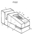
- Figure 2 its modules are shown assembled to each other.
- the franking module 1 has on its front face a slot 12 for introducing an article into the module 1.
- This module 1 is also equipped on its inclined upper face, with a display screen 14, at the rear of a keyboard 15, and with a hatch 16 for access to the print head 10, on the 'before.
- An arrow 10F illustrates the possible removal of the head 10 from the module 1, in particular for its replacement by another head.
- This franking module comprises in its internal part, in addition to the head 10, means for moving the head and the article and a machine control circuit, described below. It is simply specified opposite the control circuit, that it is preferably formed on two cards attached to the rear wall and on one of the walls side of module 1, such as the card 17 shown diagrammatically in FIG. 1.
- the letter scale module 3 is an optional machine module. It advantageously allows the measurement of the weight before the franking of each article, for the automatic calculation of the franking amount of this article by its own control circuit or that of the machine to which it is connected through the connectors 3B, 1A of the modules 3 and 1. In the absence of such a letter-weighing module in the machine, the postage amount is entered by the keyboard.
- This letter-weighing module 3 in the form of a flat box has a vertical 3D slot for receiving each item to be weighed, on its upper face. The bottom of the slot constitutes a horizontal 3P weighing pan.
- This module is electronic, it allows a selection between different weight ranges, 0-20 g, 20-50 g, 50-100 g, for example, for each item, for the calculation of the postage amount corresponding to each section by its control circuit or that of the machine.
- the power module 4 is the rearmost module of the machine.
- the power supply module 4 presented behind the letter-weighing module 3 is said to be a power module; it is equipped with its 4C cord with terminal plug for connection to a mains socket. It comprises, in known manner, transformer, rectification and filtering circuits. It is equipped with a 4I switch on one of its side faces.
- FIG 1 there is shown in correspondence with this power supply module 4 on the one hand a battery power module 4 ′ and on the other hand a battery power module 4 ⁇ .
- a battery power module 4 ′ and 4 ⁇ can be retained in place of the sector module 4, as translated by the arrows 4′F and 4 ⁇ F which correspond to them.
- These modules 4 ′, 4 ⁇ are equipped, like module 4, with a female connector 4′B or 4 ⁇ B, as the case may be.
- a battery charger 5, with cord 5C with terminal plug for connection to the mains and equipped with a male connector 5A for the female connector 4 ⁇ B, is provided for recharging the battery module 4 ⁇ , then considered retained in the machine.
- the accounting module 2 with memory and microprocessor, of the smart card type, is assigned to postage transactions of the machine, whether this machine is used in post-payment or in pre-payment.
- prepayment it is preferably a credit card acquired by the user, which is debited on each postage of the corresponding amount and allows postage to be made until the available credit is equalized.
- prepayment it can also be a card for loading funds into the machine.
- post-payment and, if necessary, in pre-payment when the machine has been previously recharged in funds, it is, moreover, an identification card of the machine and possibly of the user.
- the machine further includes, optionally, a memory module 2 ′, also of the smart card type, which is externally analogous to the accounting module 2 and has its connection pad 2′A and which is connected in place of the accounting module 2.
- This memory module 2 ′ is also known as an advertising flame registration card.
- Such a memory card 2 ′ published by a specialized service at the request of the user, allows the user to record the advertisement, which is defined therein, in his machine.
- the user may, instead of acquiring such a memory card 2 ′, have a cord 2F for connecting the machine to an external circuit, for example to a microcomputer, with the appropriate computer program, to enable him to compose his advertising flame and the definition data of this flame himself and to record in the machine these data defining this advertising flame; the user can also save addresses of recipients of his mail folds, in his machine.
- This connection cord 2F is at the end of connection to the franking machine which is in the form of a connection module 2 ⁇ of the card type and externally identical to module 2.
- This connection module 2 ⁇ has its connection pad marked in 2 ⁇ A, and is connected in place of module 2 on module 1.
- the arrow 2′F or the arrow 2 ⁇ F translates the optional use of the module or memory card 2 ′ or of the module or connection card 2 ⁇ to a microcomputer, for recording in the machine any new advertising flame and, where appropriate, addresses.
- the keyboard 15 of the printing module also constitutes a means of input of alphanumeric data for the recording of a so-called simplified advertising flame and of addresses.
- This same keyboard is, moreover, a means of selecting a machine operating mode from among several possible operating modes.
- This module which is the largest in the machine remains very small and is of low weight; for example its rear face is 100 x 105 mm, in height and width, its lower or upper face has a length of the order of 150 mm, its weight is less than a kilogram.
- the head 10 is carried by a support 20. It is removably and lockable mounted on its support by means not shown, while being connected through its support to the control circuit mounted in this module.
- This print head is as such known. It is a small component, such as an inkjet or needle print head. It is preferably an ink jet head such as that known under the name THINK JET from the company HEWLETT PACKARD. It has a limited number of ink ejection nozzles, with a small pitch between them and in a row on a face called the base of the head. It has an internal ink tank to supply its nozzles.
- a network of control elements is associated with the individual nozzles.
- a network of control links for this network of elements terminates on the base of the head, on a so-called rear side of the row of nozzles. It is connected to the support carrying the head, from where the connections go to the machine control circuit.
- Such an ink jet printhead has a limited printing time and constitutes a disposable component which is replaced by an identical new head, when its internal ink reserve is used up.
- the base has simply been identified by the reference 10A and its row of nozzles by the reference 10B. It is further specified that the row of nozzles comes in front of the support 20 and extends parallel to the front face of the module 1, that is to say in the plane of Figure 3; it gives the direction of one of the dimensions of an area to be printed on the article, but is of length less than this dimension.
- the slot 12 is defined between two fixed horizontal plates, 25 and 26, extending under the head, and spaced from each other by the maximum thickness of the articles to be introduced into the machine.
- the lower plate 25 is called the introduction plate.
- the upper plate 26 is called the printing plate.
- This printing plate is at a short distance from the row of nozzles 10B. It has a window 26A to the right of the row of nozzles, through which is carried out the printing of a postage stamp, of the sticker of the office of attachment of the machine and, if desired of an advertising flame, on the article.
- the window is wide, appearing in FIG. 3, slightly greater than the length of the row of nozzles; its length corresponds to the height of the imprints to be printed, that is to say of the order of 25 mm.
- the slot 12 has its ends open on the two lateral sides of the franking module, in its front part. 12A has its flared entry end of each item and 12B its exit end.
- This slot 12 is equipped with means 30 ensuring the advance and the maintenance of the article in the printing position relative to the head and its row of nozzles.
- These means 30 comprise, on the side of the inlet end 12A, a smooth roller 31 mounted above the slot, and a roller 32, with peripheral grooves not referenced, mounted below the slot.
- rollers 31 and 32 are driven according to arrows 31A and 32B and the belts according to arrow 33A, for advancing the article.
- These same means 30 further comprise a pair of arms 35 articulated on the axis of the roller 32 and carrying between them the deflection roller 34. This pair of arms is biased by springs 36, to drive the deflection roller through the slot, as shown by arrow 35A. It urges the set of belts 33 against the printing plate 26 for the application of any article, introduced into the end 12A of the slot 12 and caught between the rollers 31 and 32 against this printing plate, during his advance along the slit.
- roller 31 is flush with the upper side of the slot 12; the roller 32 carrying the belts 33 is in turn biased by springs 37 to come into pressure against the roller 31 through the slot, to cooperate in a good application of any article against the printing plate 26, whatever the thickness of this article.
- This slot 12 is further equipped with a sensor 40A, 40B for entry of an article into the slot, mounted close to the rollers 31 and 32, on the side of the entry 12A.
- This sensor provides the drive control of the rollers 31 and 32, for the advance of the article for a printing cycle which it triggers.
- the slot is equipped with another sensor 41A, 41B, mounted slightly beyond the row of nozzles. This sensor 41A, 41B provides detection of the presence of an article in a printing position under the head. It triggers a printing phase of the printing cycle. It also triggers an article ejection phase, after this printing phase.
- a third sensor 42A, 42B is mounted to detect an associated flag 43, which is carried by the support or slide 20.
- This sensor 42A, 42B detecting the flag defines an impression reference position for the print command and therefore ink jets during the printing phase.
- FIG. 4 and / or 5 it can be seen, in addition to the description above, that the roller 31 is held between two bearings 44A, 44B and that the roller 32 is itself held between two bearings 45A, 45B which are biased by the springs 37.
- the bearings 44A, 44B for the roller 31 also constitute the support for the rod 21 for guiding the slide 20.
- the bearing 44A also has a notch 46 at the base of the head 10. This notch is delimited by the introduction plate 25, formed directly or attached to this bearing 44A, it receives an edge of the printing plate which is held there. These plates 25 and 26 are therefore fixed opposite the base of the head mounted on the slide.
- the bottom of the notch 46, between the plates 25 and 26 defines the bottom of the slot 12. It is identified by the reference 46A.
- the two sensors mounted along the slot 12, designated simply by reference 40, 41, are at the bottom 46A of the slot 12 ( Figure 4).
- the displacement of the slide 20 on the guide rod 21 has been identified by the double arrow 20A, and the slide 20 and the head 10 in their two extreme positions have been illustrated in solid lines and in dotted lines. Between these two extreme positions, the row of nozzles 1B moves on the same trajectory, alternately in one direction and the other.
- the flag 43 integral with the slide 20 and associated with the third sensor designated simply by the reference 42, advantageously has a slot 47 making it possible to detect one, and therefore the other, of the directions of movement of the row of nozzles.
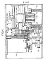
- the means 22 and 23 for actuating and controlling the slide 20 on the guide rod 21 and means generally designated by the reference 50 for driving the rollers 31 and 32 are described below with reference to FIGS. 4 and 5
- These means are coupled to a common motor 51, which controls them. They are housed with the motor 51 in the rear part of the franking module 1, behind the slide 20.
- a motor pinion 52 drives a distribution shaft 53 which itself drives the means 23, 22 and the means 50.
- This shaft 53 carries a wheel 54 at one of its ends, with continuous internal toothing 54A, on which the drive pinion 52 engages.
- a cam mounted at the bottom of the shaft 53, at its other end and made integral with this shaft constitutes the means 23.
- the cam bears this reference 23. It has its periphery in the shape of a heart, with a projecting point 23A and a notch 23B opposite.
- the wheel 54 belongs to the means 50. It has for this purpose on its periphery two teeth 54B opposite one another.
- the choice of two teeth 54B results from the heart shape of the cam 23. These teeth are both slightly offset from the point and the notch of the cam to which they correspond respectively during the drive on one revolution of the cam and of the wheel.
- These means 50 further comprise pinions 55 to 59 for coupling the wheel 54 with the rollers 31 and 32.
- the pinion 55 is cylindrical, it comes on the periphery of the wheel 54 in engagement with the two teeth 54B when each of the teeth comes to his level.
- the pinions 56 and 57 form a pair of bevel gears between the shaft of the pinion 55 and the shaft of the transverse roller 31 which carry them, respectively, for driving the roller 31.
- the pinion 58 cylindrical, is mounted on the 'roller shaft 31; it is shown from a single piece with the bevel pinion 57.
- the pinion 59 also cylindrical, is mounted on the shaft of the roller 32 and engages on the pinion 58, it drives the roller 32, in synchronism with the roller 31 but in reverse.
- the means 22 couple the cam 23 and the slide 20. They comprise a small lever 60 articulated at one end and with a bent end spout 60A, opposite, bearing on the periphery, a connecting rod 61 for driving the slide 20 and a vertical shaft 62 for coupling between the lever 60 and the link rod 61. Springs 63 act on the shaft 62, in order to request the maintenance of the lever 60 in abutment against the periphery of the cam 23. A finger 20D on the slide 20 is retained in an oblong slot 61D of the rod 61, for fixing the rod 61 on the slide 20 ( Figure 5).
- the rod drives the slide 20 along its guide rod 21, in one direction then the other.
- the tip 23A and the notch 23B give the reversal of the direction of drive of the slide, with an increasing speed at each start of the outward travel as return and a decreasing speed at the end of the outward travel as return.
- the two opposite convex parts of the cam which exclude the zones with the point and the notch, are defined to give a constant speed to the slide 20; they define the useful part, traversed at constant speed, of the outward and return stroke of the slide 20 on the guide rod 21. The printing of each imprint is carried out on this useful part.
- the means 50 in turn ensure the drive of the rollers 31 and 32 and therefore of the article along the slot of the machine when the slide 20 with the head 10 is stopped or practically stopped.
- the memory 71 is called the memory of the financial meters and of the franking operations of the machine.
- the memory 72 constitutes a source of data for the matrix definition of the imprints of the postage stamp and of the sticker of the home office of the machine, without their variable data of value and date in these imprints.
- the memory 73 constitutes a data source for defining an advertising flame.
- the memory 74 constitutes a source for other fixed data, in particular address definition data. of the sender and recipients of mail folds.
- the financial and advertising interface circuits 86 and 87 are carried by a first control card mounted in the franking module on its rear wall; the other interface circuits, the microprocessor and the set of memories are on the second control card 17 also mounted in the franking module but on one of its side walls.
- These last two recording operating modes consist of a simple data transfer, from module 2 ′ or keyboard 15, or through module 2 ⁇ , then connected to the postage 1, to memory 73 or 74 concerned.
- the transfer procedure with modules 2 ′ and 2 ⁇ is delivered with modules 2 ′, 2 ⁇ .
- the one with the keyboard is integrated into the control circuit 17 in the form of an appropriate processing unit, not shown, which processes the ordered data to be recorded in response to the entered alphanumeric data, for subsequent printing.
- the franking, slip edition and addressing procedures lead to printing operations carried out by the head, which are more machine specific. Each printing operation is performed in one printing cycle. This printing cycle takes place in an analogous manner regardless of the operating mode concerned. It is described below with reference to the figures, for the franking operation of an article, which is linked to an additional preliminary step to define the amount of franking.
- this preliminary step consists of simply inserting the article into the 3D slot of the letter-weighing module, giving rise to the automatic calculation of the postage amount by the machine, with displaying the amount on the screen, then confirming the displayed amount using the keyboard.
- this preliminary step consists of entering the postage amount directly by the keyboard, entering this amount giving rise to its display on the screen, then validating the amount displayed, by the keyboard.
- the printing cycle is executed under the control of the microprocessor, from the introduction of the article to be franked in the slot 12 of the machine. It is triggered by the sensor 40 as soon as it detects the presence of the article in the entrance to the slot 12. It breaks down into a phase of bringing the article into position printing, a printing phase and an ejection phase of the article.
- the motor 51 is controlled and drives the distribution shaft 53.
- one of the teeth 54B of the wheel 54 engages the pinion 55 and the cam 23 makes a U-turn. This results in an advance, one step, of the article, then a displacement of the slide 20 and of the head 10 in a first direction along the guide rod 21.
- the distribution shaft 53 defines by complete revolution a same repetitive sequence, in advance of the article by 2 steps and movement of the head on the same race traveled in one direction after the first of two steps and in the other after the other step.
- Each advance of the article made along the row of nozzles is equal to the length of the row of nozzles. The movement of the head is transverse to the row of nozzles, therefore to the direction of advance of the article.
- the phase of bringing the article into the printing position and the ejection phase are provided by the sole control of the motor 51.
- the sensor 41 defines the end of the phase of bringing the article into the printing position. impression. In this printing position, the article largely engaged in the slot 12 is under the printing head 10, it is therefore well pressed against the printing plate 26 and will remain so throughout the printing phase.
- the printing phase is executed, as soon as the sensor 41 has detected the presence of the article, under the control of the sensor 42 detecting the flag 43 and its slot 47.
- the print command is initialized by the sensor 42. This printing is carried out on the only useful part of the outward and return stroke of the head which is traversed at constant speed.
- the round trip of the head and the advancement in steps of the article lead to a scanning, by contiguous lines, of the printing areas of the stamp, the sticker of the home office and the advertising flame on the article, done successively and according to the height of the zones.
- the number of lines scanned, from the start of printing, is also detected from sensor 42. This number allows the microprocessor to control the end of printing of the stamp, the home office sticker and the advertising flame. .
- This printing phase is given by a defined number of lines scanned during this printing cycle, for each operating mode; this number cannot exceed a given maximum number. It gives rise to the ejection phase of the article.
- the end of this ejection phase is given by the sensor 41 after the article has passed under this sensor. The sensor 41 controls the stopping of the motor 51.
- the machine according to the invention due to its possible modular construction, is advantageously made adaptable to the needs of each user. It is inexpensive and with its disposable inkjet printhead and directly replaceable when the ink supply is used up.
Landscapes
- Physics & Mathematics (AREA)
- General Physics & Mathematics (AREA)
- Devices For Checking Fares Or Tickets At Control Points (AREA)
Claims (31)
- Kleinfrankiermaschine, die einen Druckkopf (10) mit in einer auf einer Seite (10A), Basis des Kopfs genannt, angeordneten Reihe (10B) liegenden einzelnen Druckelementen, Mittel zur Relativverschiebung des Kopfes bezüglich des Poststücks, Mittel (40 bis 42) zur Erfassung des Poststücks bezüglich des Kopfes, eine mit dem Kopf gekoppelte Quelle (70) für die zu druckenden Daten und Steuermittel (17) zum Druck der Daten aufweist, dadurch gekennzeichnet, daß- die Quelle (70) mindestens eine erste Quelle (72) für die matrixförmige Definition eines Freistempels und eines Poststempels des Postamts, dem die Maschine zugewiesen ist, für eine Druckzone mit definierten Querabmessungen aufweist,- der Kopf (10) eine begrenzte Anzahl von einzelnen Druckelementen enthält, deren Reihe in Richtung einer der Abmessungen der Zone verläuft, aber eine geringere Länge als diese Abmessung besitzt,- die Mittel zur Verschiebung erste Mittel (30) zur Verschiebung des Poststücks entlang der Reihe von Druckelementen und zweite Mittel (20 bis 22) zur Verschiebung des Kopfes quer zur Reihe von Druckelementen enthalten,- und daß die Steuermittel (17) einen Mikroprozessor enthalten und eine Druckzyklus definieren, der von den Erfassungsmitteln (40 bis 42) gestartet und kontrolliert wird, während dem das Poststück in Schritten gleich der Länge der Reihe von Druckelementen befördert wird und der Kopf sich zwischen jedem Vorschubschritt abwechselnd nach einem ersten Schritt in einer Richtung und nach dem nächsten Schritt in der Gegenrichtung verschiebt, wobei die Zone auf dem Poststück mit der Überstreichung aufeinanderfolgender Zeilen über die Zone während einer Druckphase bedruckt wird, worauf das poststück ohne weiteren Druck während einer Auswurfphase ausgeworfen wird.
- Frankiermaschine nach Anspruch 1, dadurch gekennzeichnet, daß der Kopf (10) abnehmbar auf den Mitteln zur Verschiebung montiert ist, die einen als Schlitten auf einem horizontalen Führungsstab (21) montierten Träger (20) enthalten, der die mögliche Bahn des Kopfes in der anderen Dimension der Druckzone definiert.
- Frankiermaschine nach Anspruch 2, dadurch gekennzeichnet, daß der Kopf ein Tintenstrahl-Druckkopf mit begrenzter Druckdauer ist und ein Verbrauchsbauteil bildet, das in der Maschine ausgetauscht wird.
- Frankiermaschine nach einem der Ansprüche 2 und 3, dadurch gekennzeichnet, daß die ersten Mittel zum Vorschub des Poststücks in einem Schlitz (12) montiert sind, der Einführungsschlitz genannt wird und sich unter dem Kopf und zu beiden Seiten des Kopfes erstreckt sowie seitlich offen ist, indem er eine seitlichen Eingang (12A) und einen seitlichen Ausgang (12B) für jedes Poststück definiert.
- Frankiermaschine nach Anspruch 4, dadurch gekennzeichnet, daß die ersten Vorschubmittel (30) elastische Mittel (36, 37) aufweisen, die das Poststück in Richtung auf den Druckkopf gegen eine Platte (26) drücken, Druckplatte genannt, die fest unmittelbar unter dem Kopf (10) montiert ist und ein Druckfenster (26A) in Höhe der Reihe von Druckelementen und im wesentlichen mit einer Länge entsprechend der Bewegungsstrecke des Kopfes enthält.
- Frankiermaschine nach Anspruch 5, dadurch gekennzeichnet, daß sie einen gemeinsamen Motor (51) zum Antrieb der ersten und zweiten Mittel zur Verschiebung des Poststücks und des Kopfes, eine Verteilwelle (53), die von dem Motor angetrieben wird, erste Kopplungsmittel (50) zwischen der Welle und den ersten Mitteln (30) zur Verschiebung des Poststücks und zweite Mittel (23) zur Kopplung zwischen der Welle und den zweiten Mitteln zur Verschiebung des Kopfes aufweist.
- Frankiermaschine nach Anspruch 6, dadurch gekennzeichnet, daß die ersten Mittel zur Verschiebung des Poststücks und die elastischen Mittel ein Paar von Antriebsrollen (31, 32) aufweisen, die zu beiden Seiten des Schlitzes auf der Eingangsseite (12A) montiert sind, wobei die untere Rolle (32) elastisch in den Schlitz vorspringt und gegen die andere Rolle drückt und wobei ein Satz von zwischen der unteren Rolle und einer Umlenkrolle (34) auf der Ausgangsseite (12B) gespannten Riemen elastisch in Richtung auf den Kopf beaufschlagt ist.
- Frankiermaschine nach Anspruch 7, dadurch gekennzeichnet, daß die Umlenkrolle (34) auf zwei Armen (35) montiert ist, die auf der Achse der unteren Rolle (32) gelenkig gelagert und durch Federn (36) in Richtung auf den Andruck der Riemen gegen die Druckplatte (26) beaufschlagt sind.
- Frankiermaschine nach einem der Ansprüche 7 und 8, dadurch gekennzeichnet, daß die ersten Kopplungsmittel (50) ein Zahnrad (54) mit regelmäßig ausgeschnittenen Zähnen (54B), das auf der Verteilerwelle (53) sitzt, und einen Satz von Ritzeln (55 bis 59) aufweisen, die miteinander und mit den ausgeschnittenen Zähnen des Zahnrads kämmen und den Antrieb der beiden Antriebsrollen (31, 32) bewirken.
- Frankiermaschine nach Anspruch 9, dadurch gekennzeichnet, daß das Zahnrad (54) zwei einander gegenüberliegende Zähne (54B) für den Antrieb des Satzes von Ritzeln (55 bis 59) besitzt.
- Frankiermaschine nach Anspruch 10, dadurch gekennzeichnet, daß das Zahnrad (54) außerdem eine kontinuierliche Innenverzahnung (55A) besitzt, die mit einem auf der Motorwelle (51) sitzenden Ritzel (52) kämmt, um die von der Achse des Zahnrads gebildete Verteilerwelle anzutreiben.
- Frankiermaschine nach einem der Ansprüche 6 bis 11, dadurch gekennzeichnet, daß die zweiten Kopplungsmittel eine Nockenscheibe (23) in Form eines Herzens, die auf der Verteilerwelle sitzt, einen Hebel (60), der auf die Nockenscheibe drückt, und eine Stange (61) enthalten, die mit dem Hebel gekoppelt und am Schlitten (20) befestigt ist, wobei die Nokkenscheibe die Antriebssteuerung des Kopfes in der einen und der anderen Richtung mit konstanter Geschwindigkeit über den größten Teil seines Wegs und mit einer progressiven Beschleunigung und Verzögerung nach und vor jedem Halt des Kopfs am Ende der Strecke auf dem Führungsstab (21) sichert.
- Frankiermaschine nach einem der Ansprüche 6 bis 12, dadurch gekennzeichnet, daß die Erfassungsmittel eine erste Sonde (41) im wesentlichen in Höhe des Kopfes auf der Seite (12B) des Ausgangs des Poststücks und eine zweite Sonde (40) im wesentlichen am Eingang (12A) in den Schlitz (12) aufweisen, wobei die zweite Sonde die Antriebssteuerung des Motors (51) startet, sobald das Poststück bei ihr erfaßt wurde, während die erste Sonde (41) die Druckphase auslöst, sobald das Poststück bei ihr erfaßt wurde, und das Anhalten des Motors veranlaßt, sobald das Poststück den Sondenbereich verlassen hat.
- Frankiermaschine nach Anspruch 13, dadurch gekennzeichnet, daß die Erfassungsmittel weiter eine Lasche (43) auf dem Schlitten (21) und eine dritte Sonde (42) zur Erfassung der Lasche aufweisen, um die Drucksteuerung während der Verschiebung des Kopfes auf dem Führungsstab (21) zu initialisieren.
- Frankiermaschine nach Anspruch 14, dadurch gekennzeichnet, daß die Lasche (43) einen Schlitz (47) aufweist, der der Erfassung der Verschieberichtung des Schlittens (20) auf dem Führungsstab (21) in der dritten Sonde (42) dient.
- Frankiermaschine nach einem der Ansprüche 1 bis 15, die weiter eine Tastatur (15) und ein Anzeigefeld (16) auf einer Seite der Maschine besitzt, die mit der Steuerschaltung gekoppelt sind, dadurch gekennzeichnet, daß die Datenquelle weiter eine zweite Datenquelle (73) für die matrixartige Definition eines Werbeslogans in einem Teil der Druckzone enthält, die mit dem Kopf gekoppelt ist und aufgrund einer ersten selektiven Steuerung über die Tastatur nach Wunsch mit dem Freistempel und dem Poststempel während der Druckphase des Zyklus den Druck des Werbeslogans steuert.
- Frankiermaschine nach Anspruch 16, dadurch gekennzeichnet, daß die Tastatur (15) außerdem ein Mittel zur Auswahl eines Operationsmodus ist, bei dem Daten des Werbeslogans in die zweite Quelle (73) geladen werden, und ein Mittel zur Eingabe der Daten des dann vereinfachten Werbeslogans ist.
- Frankiermaschine nach einem der Ansprüche 16 und 17, dadurch gekennzeichnet, daß die Datenquelle weiter eine dritte Quelle (74) aufweist, die der matrixartigen Definition von Adressendaten für die Poststücke dient und mit dem Kopf gekoppelt ist sowie unter der Kontrolle der Steuerschaltung (17) aufgrund einer zweiten über die Tastatur eingegebenen selektiven Steuerung den Druck der Adressendaten auf dem Poststück steuert, wobei dann die erste und die zweite Quelle (72, 73) vom Kopf isoliert sind.
- Frankiermaschine nach Anspruch 18, dadurch gekennzeichnet, daß die Tastatur (15) weiter ein Mittel zur Auswahl eines Operationsmodus, bei dem Adressen in die dritten Quelle (74) geladen werden, und ein Mittel zur Eingabe der Adressen ist.
- Frankiermaschine nach einem der Ansprüche 16 bis 19, mit einem Speicher (71) für die Kontostände der Maschine in der Steuerschaltung, dadurch gekennzeichnet, daß die Tastatur weiter ein Mittel zur Auswahl eines Listenausgabemodus ist, bei dem der Speicher für die Kontostände ausgelesen wird, um mit dem Kopf anstatt des Poststückstempels eine Liste der Buchungsvorgänge auszudrucken, während die Datenquelle vom Kopf isoliert ist.
- Frankiermaschine nach einem der Ansprüche 16 bis 20, dadurch gekennzeichnet, daß sie weiter eine erste Karte (2) mit Speicher und Mikroprozessor, Chipkarte genannt, aufweist, die den Buchungsvorgängen der Maschine dient und die mit der Steuerschaltung (17) gekoppelt ist, wobei sie im normalen Frankiermodus integraler Bestandteil der Maschine ist.
- Frankiermaschine nach Anspruch 21, dadurch gekennzeichnet, daß sie weiter eine zweite Karte (2') mit Speicher aufweist, die der Einspeicherung von Daten des Werbeslogans dient, Werbekarte genannt, und anstelle der Chipkarte eingesteckt wird und dann mit der Steuerschaltung (17) gekoppelt ist, um die Daten dieser Karte in die zweite Quelle (73) unter Kontrolle durch die Steuerschaltung und aufgrund einer dritten selektiven Steuerung über die Tastatur im Werbestempel-Einspeichermodus der Maschine zu laden.
- Frankiermaschine nach einem der Ansprüche 21 und 22, dadurch gekennzeichnet, daß sie weiter eine dritte Karte (2˝) am Ende eines Kabels (2F) einer äußeren programmierten Schaltung zum Aufbau des Werbeslogans, Anschlußkarte genannt, aufweist, die anstelle der Chipkarte eingesteckt wird, um von der äußeren Schaltung erarbeitete Daten des Werbeslogans in die zweite Quelle (73) aufgrund einer vierten selektiven Steuerung zu laden, die über die Tastatur erfolgt und die Maschine in einen Werbeslogan-Speichermodus bringt.
- Frankiermaschine nach einem der Ansprüche 16 bis 23, dadurch gekennzeichnet, daß sie weiter eine Briefwaage (3) mit senkrechtem Aufnahmeschlitz für das Poststück aufweist, wobei der Schlitz an der Oberseite der Maschine offen ist und die Briefwaage in die Maschine integriert und mit der Steuerschaltung (17) zur Ermittlung des Frankierbetrags jedes auf die Briefwaage gelegten Poststücks gekoppelt ist.
- Frankiermaschine nach einem der Ansprüche 16 bis 24, die weiter eine integrierte Stromversorgung besitzt, dadurch gekennzeichnet, daß die Stromversorgung mit Batterien arbeitet.
- Frankiermaschine nach einem der Ansprüche 21 bis 23, dadurch gekennzeichnet, daß sie einen ersten Modul (1) aufweist, Druckmodul genannt, der als flaches, praktisch geschlossenes Gehäuse vorliegt, in dem der Kopf (10) und die ersten und zweiten Verschiebemittel (30, 20 bis 22) im vorderen Teil und die Steuermittel (17) in mindestens einem seitlichen Bereich untergebracht sind und das eine erste Anschlußfläche (11A) besitzt, die an seiner Rückwand für die an die Steuerschaltung anzuschließende Karte (2, 2′, 2˝) zugänglich und an die Steuerschaltung angeschlossen ist, wobei die Karte ihrerseits eine komplementäre Anschlußfläche (2A, 2′A, 2˝A) besitzt und eine zweiten austauschbaren Modul auf dem ersten Modul bildet.
- Frankiermaschine nach Anspruch 26, dadurch gekennzeichnet, daß der erste Modul (1) weiter einen ersten Verbinder (1A) an der Rückwand besitzt, und daß weiter ein dritter Stromversorgungsmodul (4) ebenfalls in Form eines flachen Gehäuses vorgesehen ist, dessen große Seiten der Rückwand des ersten Moduls entsprechen und von denen eine, nämlich die Vorderseite, einen zweiten Verbinder (4B) komplementär zum ersten besitzt, wobei dieser dritte Modul so unmittelbar an dem ersten angeschlossen werden kann und wobei seine Vorderseite im wesentlichen an die Rückwand des ersten Moduls angefügt ist und der zweite Modul (2, 2′, 2˝) zwischen ihnen geschützt ist.
- Frankiermaschine nach Anspruch 27, dadurch gekennzeichnet, daß der dritte Modul ein Netzmodul ist.
- Frankiermaschine nach Anspruch 27, dadurch gekennzeichnet, daß der dritte Modul ein Batteriemodul (4′) ist.
- Frankiermaschine nach Anspruch 27, dadurch gekennzeichnet, daß der dritte Modul ein Akkumulatormodul (4˝) ist, dem ein entsprechendes Ladegerät (5) mit einem komplementären Verbinder (5A) zum zweiten Verbinder und mit einem Netzkabel zugeordnet ist.
- Frankiermaschine nach einem der Ansprüche 27 bis 30, dadurch gekennzeichnet, daß sie außerdem einen vierten Modul (3) enthält, der eine Briefwaage bildet und auch ein flaches Gehäuse besitzt, dessen große Seiten der Rückwand des ersten Moduls entsprechen und das einen dritten, zum ersten Verbinder komplementären Verbinder (3B) an einer dieser großen Seiten und einen vierten Verbinder (3A) identisch zum ersten Verbinder auf der anderen großen Seite besitzt, sowie einen senkrechten und oben offenen Schlitz (3D) zur Aufnahme eines Poststücks und eine Wägeplatte (3P) am Grund des Schlitzes aufweist, wobei dieser Modul zwischen den ersten und den dritten Modul (1, 4) eingefügt ist, an die er angeschlossen ist und im wesentlichen anliegt und so den zweiten Modul (2, 2′, 2˝), der an den ersten Modul angeschlossen ist, schützt.
Applications Claiming Priority (2)
| Application Number | Priority Date | Filing Date | Title |
|---|---|---|---|
| FR8908826 | 1989-06-30 | ||
| FR8908826A FR2649230B1 (fr) | 1989-06-30 | 1989-06-30 | Machine a affranchir miniature |
Publications (2)
| Publication Number | Publication Date |
|---|---|
| EP0405357A1 EP0405357A1 (de) | 1991-01-02 |
| EP0405357B1 true EP0405357B1 (de) | 1994-11-02 |
Family
ID=9383354
Family Applications (1)
| Application Number | Title | Priority Date | Filing Date |
|---|---|---|---|
| EP19900111868 Expired - Lifetime EP0405357B1 (de) | 1989-06-30 | 1990-06-22 | Miniaturfrankiermaschine |
Country Status (3)
| Country | Link |
|---|---|
| EP (1) | EP0405357B1 (de) |
| DE (1) | DE69013769T2 (de) |
| FR (1) | FR2649230B1 (de) |
Cited By (1)
| Publication number | Priority date | Publication date | Assignee | Title |
|---|---|---|---|---|
| US7343359B2 (en) | 2001-03-21 | 2008-03-11 | Francotyp - Postalia Gmbh | Franking machine having a retrofittable weighing device |
Families Citing this family (8)
| Publication number | Priority date | Publication date | Assignee | Title |
|---|---|---|---|---|
| GB9127479D0 (en) * | 1991-12-30 | 1992-02-19 | Alcatel Business Systems | Franking machine |
| DE4213278C2 (de) * | 1992-04-16 | 1998-02-19 | Francotyp Postalia Gmbh | Anordnung zum Frankieren von Postgut |
| DE59309710D1 (de) * | 1992-04-16 | 1999-09-09 | Francotyp Postalia Gmbh | Verfahren zur Dateneingabe in einer Frankiermaschine, Anordnung zum Frankieren von Postgut und zur Erzeugung eines jeweils einer Kostenstelle zugeordneten Frankierbildes |
| US5699258A (en) * | 1992-04-16 | 1997-12-16 | Francotyp-Postalia Ag & Co | Assembly for franking postal matter, and multi-carrier shipping system |
| US5490077A (en) * | 1993-01-20 | 1996-02-06 | Francotyp-Postalia Gmbh | Method for data input into a postage meter machine, arrangement for franking postal matter and for producing an advert mark respectively allocated to a cost allocation account |
| DE59309015D1 (de) * | 1993-12-16 | 1998-10-29 | Francotyp Postalia Gmbh | Verfahren zum Betreiben einer Frankiermaschine |
| FR2872947B1 (fr) * | 2004-07-08 | 2007-04-20 | Neopost Ind Sa | Tampon a affranchir electronique |
| DE102006022210A1 (de) * | 2006-05-11 | 2007-11-15 | Francotyp-Postalia Gmbh | Anordnung und Verfahren zum Erstellen eines Frankierabdrucks |
Family Cites Families (9)
| Publication number | Priority date | Publication date | Assignee | Title |
|---|---|---|---|---|
| BE850225R (fr) * | 1977-01-07 | 1977-07-07 | Photronic Internat Establishme | Machine postale combinee |
| IT1162897B (it) * | 1983-07-08 | 1987-04-01 | Telefonia Automazione Elettron | Apparecchiatura timbatrice |
| US4831554A (en) * | 1986-04-10 | 1989-05-16 | Pitney Bowes Inc. | Postage meter message printing system |
| WO1988001818A1 (en) * | 1986-09-02 | 1988-03-10 | Wright Christopher B | Automated transaction system using microprocessor cards |
| US4813912A (en) * | 1986-09-02 | 1989-03-21 | Pitney Bowes Inc. | Secured printer for a value printing system |
| GB8714192D0 (en) * | 1987-06-17 | 1987-07-22 | Roneo Alcatel Ltd | Franking machine |
| GB2208367B (en) * | 1987-07-09 | 1991-07-03 | Alcatel Business Systems | Franking machine |
| US4787311A (en) * | 1987-08-19 | 1988-11-29 | Pitney Bowes Inc. | Mailing machine envelope transport system |
| US4809015A (en) * | 1988-03-14 | 1989-02-28 | Eastman Kodak Company | Continuous ink jet printer having modular print head assembly |
-
1989
- 1989-06-30 FR FR8908826A patent/FR2649230B1/fr not_active Expired - Fee Related
-
1990
- 1990-06-22 DE DE1990613769 patent/DE69013769T2/de not_active Expired - Fee Related
- 1990-06-22 EP EP19900111868 patent/EP0405357B1/de not_active Expired - Lifetime
Cited By (1)
| Publication number | Priority date | Publication date | Assignee | Title |
|---|---|---|---|---|
| US7343359B2 (en) | 2001-03-21 | 2008-03-11 | Francotyp - Postalia Gmbh | Franking machine having a retrofittable weighing device |
Also Published As
| Publication number | Publication date |
|---|---|
| EP0405357A1 (de) | 1991-01-02 |
| DE69013769T2 (de) | 1995-03-09 |
| FR2649230B1 (fr) | 1993-11-26 |
| FR2649230A1 (fr) | 1991-01-04 |
| DE69013769D1 (de) | 1994-12-08 |
Similar Documents
| Publication | Publication Date | Title |
|---|---|---|
| EP0405357B1 (de) | Miniaturfrankiermaschine | |
| EP0264502B1 (de) | Automatische Postbehandlungsvorrichtung | |
| FR2622325A1 (fr) | Appareil d'affranchissement amovible comportant un couvercle de la matrice d'impression des valeurs d'affranchissement | |
| EP0405356B1 (de) | Büromaschine zum Versenden von Poststücken | |
| EP0191678B1 (de) | Einrichtung zur Bearbeitung von Belegen, insbesondere von Schecks | |
| EP0903699A1 (de) | System zur Vorbereitung von Poststücken | |
| EP0978105B1 (de) | Vorrichtung zur frankierung und adressierung | |
| EP1224082B1 (de) | Druckmodul für zwei druckträger und mit solchen modulen ausgerüstete automaten | |
| FR2666429A1 (fr) | Processeur de cartes. | |
| EP0646421B1 (de) | Verbesserte Anlage zum Identifizieren und kontinuierlich Wiegen eines Paketes mit einem von einer Balkenkodeanordnung versehenen Etikette | |
| CH679958A5 (de) | ||
| KR100584523B1 (ko) | 무인 우편물 접수기 | |
| FR2478850A1 (fr) | Dispositif distributeur de tickets de caisse pour l'enregistrement des prix de marchandises, tel que balance calculatrice de prix avec imprimante | |
| EP1193655A1 (de) | Mehrzweckfrankiermaschine | |
| CH680540A5 (de) | ||
| FR2493230A1 (fr) | Appareil d'ecriture de cheques | |
| EP1396823A2 (de) | Ausgabevorrichtung für Haushaltgasflaschen | |
| EP0604296B1 (de) | Elektronische Frankiermaschine mit zwei Drucktrommeln für feste und variable Daten | |
| CH678161A5 (de) | ||
| FR2613511A1 (fr) | Automate de paiement delivrant un justificatif | |
| CH679345A5 (de) | ||
| FR2468166A1 (fr) | Machine pour l'impression, la delivrance et l'enregistrement comptable de billets et valeurs | |
| LU85436A1 (fr) | Machine imprimante electronique | |
| BE860633R (fr) | Machine postale combinee | |
| JPH0631559Y2 (ja) | 保険証書受付装置 |
Legal Events
| Date | Code | Title | Description |
|---|---|---|---|
| PUAI | Public reference made under article 153(3) epc to a published international application that has entered the european phase |
Free format text: ORIGINAL CODE: 0009012 |
|
| AK | Designated contracting states |
Kind code of ref document: A1 Designated state(s): DE FR GB |
|
| 17P | Request for examination filed |
Effective date: 19910624 |
|
| RAP1 | Party data changed (applicant data changed or rights of an application transferred) |
Owner name: NEOPOST INDUSTRIE |
|
| 17Q | First examination report despatched |
Effective date: 19930917 |
|
| GRAA | (expected) grant |
Free format text: ORIGINAL CODE: 0009210 |
|
| AK | Designated contracting states |
Kind code of ref document: B1 Designated state(s): DE FR GB |
|
| REF | Corresponds to: |
Ref document number: 69013769 Country of ref document: DE Date of ref document: 19941208 |
|
| GBT | Gb: translation of ep patent filed (gb section 77(6)(a)/1977) |
Effective date: 19941122 |
|
| PLBI | Opposition filed |
Free format text: ORIGINAL CODE: 0009260 |
|
| 26 | Opposition filed |
Opponent name: PITNEY BOWES, INC. Effective date: 19950801 |
|
| PLBF | Reply of patent proprietor to notice(s) of opposition |
Free format text: ORIGINAL CODE: EPIDOS OBSO |
|
| PLBO | Opposition rejected |
Free format text: ORIGINAL CODE: EPIDOS REJO |
|
| PLBN | Opposition rejected |
Free format text: ORIGINAL CODE: 0009273 |
|
| STAA | Information on the status of an ep patent application or granted ep patent |
Free format text: STATUS: OPPOSITION REJECTED |
|
| 27O | Opposition rejected |
Effective date: 19961130 |
|
| REG | Reference to a national code |
Ref country code: GB Ref legal event code: IF02 |
|
| PGFP | Annual fee paid to national office [announced via postgrant information from national office to epo] |
Ref country code: DE Payment date: 20080620 Year of fee payment: 19 |
|
| PGFP | Annual fee paid to national office [announced via postgrant information from national office to epo] |
Ref country code: FR Payment date: 20080613 Year of fee payment: 19 |
|
| PGFP | Annual fee paid to national office [announced via postgrant information from national office to epo] |
Ref country code: GB Payment date: 20080620 Year of fee payment: 19 |
|
| GBPC | Gb: european patent ceased through non-payment of renewal fee |
Effective date: 20090622 |
|
| REG | Reference to a national code |
Ref country code: FR Ref legal event code: ST Effective date: 20100226 |
|
| PG25 | Lapsed in a contracting state [announced via postgrant information from national office to epo] |
Ref country code: FR Free format text: LAPSE BECAUSE OF NON-PAYMENT OF DUE FEES Effective date: 20090630 |
|
| PG25 | Lapsed in a contracting state [announced via postgrant information from national office to epo] |
Ref country code: GB Free format text: LAPSE BECAUSE OF NON-PAYMENT OF DUE FEES Effective date: 20090622 |
|
| PG25 | Lapsed in a contracting state [announced via postgrant information from national office to epo] |
Ref country code: DE Free format text: LAPSE BECAUSE OF NON-PAYMENT OF DUE FEES Effective date: 20100101 |