EP0405367A1 - Procédé pour le maintien de la fonction correcte d'un dispositif de surveillance se déplaçant le long de métiers à filer - Google Patents
Procédé pour le maintien de la fonction correcte d'un dispositif de surveillance se déplaçant le long de métiers à filer Download PDFInfo
- Publication number
- EP0405367A1 EP0405367A1 EP90111911A EP90111911A EP0405367A1 EP 0405367 A1 EP0405367 A1 EP 0405367A1 EP 90111911 A EP90111911 A EP 90111911A EP 90111911 A EP90111911 A EP 90111911A EP 0405367 A1 EP0405367 A1 EP 0405367A1
- Authority
- EP
- European Patent Office
- Prior art keywords
- cleaning
- sensors
- working elements
- operating rotor
- cleaning device
- Prior art date
- Legal status (The legal status is an assumption and is not a legal conclusion. Google has not performed a legal analysis and makes no representation as to the accuracy of the status listed.)
- Withdrawn
Links
Images


Classifications
-
- D—TEXTILES; PAPER
- D01—NATURAL OR MAN-MADE THREADS OR FIBRES; SPINNING
- D01H—SPINNING OR TWISTING
- D01H11/00—Arrangements for confining or removing dust, fly or the like
- D01H11/005—Arrangements for confining or removing dust, fly or the like with blowing and/or suction devices
- D01H11/006—Arrangements for confining or removing dust, fly or the like with blowing and/or suction devices travelling along the machines
-
- B—PERFORMING OPERATIONS; TRANSPORTING
- B65—CONVEYING; PACKING; STORING; HANDLING THIN OR FILAMENTARY MATERIAL
- B65H—HANDLING THIN OR FILAMENTARY MATERIAL, e.g. SHEETS, WEBS, CABLES
- B65H54/00—Winding, coiling, or depositing filamentary material
- B65H54/02—Winding and traversing material on to reels, bobbins, tubes, or like package cores or formers
- B65H54/22—Automatic winding machines, i.e. machines with servicing units for automatically performing end-finding, interconnecting of successive lengths of material, controlling and fault-detecting of the running material and replacing or removing of full or empty cores
- B65H54/26—Automatic winding machines, i.e. machines with servicing units for automatically performing end-finding, interconnecting of successive lengths of material, controlling and fault-detecting of the running material and replacing or removing of full or empty cores having one or more servicing units moving along a plurality of fixed winding units
-
- B—PERFORMING OPERATIONS; TRANSPORTING
- B65—CONVEYING; PACKING; STORING; HANDLING THIN OR FILAMENTARY MATERIAL
- B65H—HANDLING THIN OR FILAMENTARY MATERIAL, e.g. SHEETS, WEBS, CABLES
- B65H2301/00—Handling processes for sheets or webs
- B65H2301/50—Auxiliary process performed during handling process
- B65H2301/53—Auxiliary process performed during handling process for acting on performance of handling machine
- B65H2301/531—Cleaning parts of handling machine
-
- B—PERFORMING OPERATIONS; TRANSPORTING
- B65—CONVEYING; PACKING; STORING; HANDLING THIN OR FILAMENTARY MATERIAL
- B65H—HANDLING THIN OR FILAMENTARY MATERIAL, e.g. SHEETS, WEBS, CABLES
- B65H2701/00—Handled material; Storage means
- B65H2701/30—Handled filamentary material
- B65H2701/31—Textiles threads or artificial strands of filaments
Definitions
- the invention relates to a method and a device for maintaining the functional reliability of an operating runner for spinning machines, which has a large number of individual functions triggering exposed sensors and a number of different types of working elements.
- optical sensors in particular no longer respond; Work organs cannot reach their end position because densified fiber cushions have built up there; The running of tapes, rovings or threads is hindered by deposits. This flight requires frequent, labor-intensive and personnel-intensive cleaning, but with insufficient care, damage or adjustments to sensors, work organs, stops and other machine elements can very easily occur.
- the present invention is based on the object of increasing the functional reliability of sensors and working elements in the operating runner for spinning machines and reducing the effort required for cleaning flight and dust.
- This object is achieved in that the sensors and the working elements are automatically subjected to periodic, mechanical cleaning.
- these correspondingly sensitive aggregates of the operating rotor are automatically acted upon at regular intervals by blown air currents which remove deposits from flight or dust.
- this exposure can take place in succession on individual sensors and working elements, as a result of which intensive cleaning is possible with an available air volume.
- the exposure to all sensors and work organs can therefore advantageously also take place simultaneously, although a higher air volume is required or cleaning is not carried out as intensively.
- cleaning can take place when the operator is outside of his normal work area, in particular on the way between two work areas that are spatially separated from one another.
- the blown air flow can be generated by blowing or suction devices present on the operating rotor if these are not required for their normal activity outside the operating range of the operating rotor.
- the fan which draws the thread on its suction side during normal operation of an automatic thread attachment device, can supply the air required for blowing off on its blowing side in cleaning operation.
- the blowing device is also arranged in a blow-off position on the spinning machine and on the path of the operator. The blow-off device is switched on when passing by, possibly even when the operating runner comes to a standstill at this blow-off position, and cleans the sensors and working elements of the operating runner and thus helps to maintain the upright position maintaining the functional reliability of this operator runner.
- the blown air can be guided through lines leading to any point to be cleaned and ending in blower nozzles.
- blowing nozzles can be assigned at least one suction nozzle which sucks off blown off deposits.
- suction nozzles instead of the aforementioned blowing nozzles.
- an operating runner 2 moves on a corresponding path between work areas A and A 'of a spin machine 1.
- This operating runner 2 can be, for example, an automatic thread application device, an automatic bobbin changing device or a similar auxiliary unit.
- an integrated cleaning device in the area between the two working areas A and A ' .
- This cleaning device can have, for example, at least one blowing nozzle, the automatic, periodic cleaning of the sensors and working elements being carried out by the corresponding air jet.
- Fig. 2 there is also the possibility that the cleaning of the sensors and the working elements of the operator 2 can be carried out by an operator's own cleaning device 3 '.
- the cleaning process will preferably be carried out again in the area between the two working areas A and A 'of the spinning machine 1.
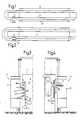
- this cleaning device 3 schematically shows a cleaning device 3 integrated in the spinning machine.
- this cleaning device 3 consists of a number of blowing nozzles 4, which are connected to one another via a line 10. This results in a number of air jets len, which are directed to the area 5 of the operating runner 2, in which exposed sensors and various work organs are located.
- the line 10 of the blowing nozzles 4 is connected to a reservoir 8 and a pump 7 via a valve 9.
- a plurality of blowing nozzles 4 are arranged one above the other, the mouthpiece of which can be made adjustable in each case in order to be able to carry out an exact adjustment in accordance with the elements to be cleaned.
- the cleaning device 3 is also located in the spinning machine 1.
- a single blowing nozzle 6 is used, which is guided so as to be vertically displaceable via an adjusting device.
- This adjustment device consists for example of at least one threaded spindle 12 which is driven by a motor 15 via a gear.
- This blowing nozzle 6 is connected to a source, i.e. a pump 7, via a flexible line 11.
- a single blowing nozzle 6 is used, which is guided in succession over the various locations to be cleaned in area 5 of the operating runner 2, in which area 5 the corresponding working elements and sensors are located, the functional reliability of which is to be maintained.
- Fig. 5 shows another embodiment of the invention, in which case the cleaning of the sensors and working elements of the operating rotor 2 (not shown in more detail) is carried out by a cleaning device 3 of the operator's own.
- a cleaning device 3 of the operator's own.
- several blowing nozzles 4 are used, which are connected to one another via a line 10, which in turn are connected to a reservoir 8 and a pump 7.
- the nozzles 4 are designed in such a way that they can be directed towards the work organs and sensors to be cleaned, so that easy adjustment is provided.
- the operating rotor 2 has a closed rear wall 20, through which air is deflected into the lower region of the operating rotor 2, where a suction device 14 is arranged.
- the air that is used to carry out the cleaning process thus flows from the blowing nozzles 4 via the corresponding sensors and working elements of the operating rotor 2 to the suction device 14.
- both a blowing nozzle 6 'and a suction nozzle 16 are used.
- the blowing nozzle 6 ' which is the main component of the cleaning device 3', in the operating rotor 2 and can be moved up and down accordingly with the aid of at least one threaded spindle 12 and the drive 15 described above.
- This blowing nozzle 6 ' can be assigned to a suction nozzle 16, the suction nozzle 6' and the blowing nozzle 16 being assigned to one another in such a way that a synchronous up and down movement results.
- the suction nozzle 16 sits on a threaded nut 18, which in turn is arranged on a threaded spindle 17, which in turn keeps its drive via a motor-gear arrangement 21.
- the rotation of the threaded spindles 12 and 17 is carried out synchronously, for example by an electronic control device, not shown, which links the drives 15 and 21 so that there is a synchronous up and down movement of the blowing nozzle 6 'together with the suction nozzle 16.
- This suction nozzle 16 is in turn connected to a suction 19 via a line 11, the aforementioned units being located in the spinning machine 1. Blown off deposits are sucked off through this suction nozzle 16, so that the functional safety of the individual working elements of an operating runner is maintained in a simple manner.
- the cleaning device 3, 3 'shown in the preceding drawings is provided with at least one pneumatic device for cleaning, for example, a guide element 27 for movably guided parts of the operator runner.
- this guide element 27 serves for the functionally correct guidance of a guided element 25, for example a slide, which is equipped with a schematically represented element 40 for blowing off a thread end.
- a housing 29 can be provided which can be pressurized and which has a small gap 28. Compressed air is supplied to the housing 29 via a line 36, this compressed air ensuring that the guide surface 26 of the guide element 27 is always cleaned.
- housings 29, 29 ' which can be acted upon by overpressure, are alternately arranged on both run-up ends 30, 31 of the guided element 25 depending on the direction of movement of this guided element 25 on the guide element 27.
- the housing 29 is connected via a line 36, the housing 29 'via a line 37 and via a common line 39 with a compressed air source 34.
- a valve 33, 33 'controlled by a control device 32 and 32' respectively.
- valves 33 and 33 ' are controlled by the aforementioned control devices so that an air consumption takes place only via the housing 29 or 29', in the direction of which the guided element 25, ie the carriage moves; If the direction of movement is downward, an air supply via line 37 into housing 29 'takes place by actuating valve 33, whereby air' exits via gap 28 'and thus cleans guide surface 26 of guide element 27; when the guided element 25 moves upward, air is supplied to the housing 29.
- the pneumatic device has at least one control unit 32, 32 'at least one element 33, 33' connected to a pressure source 34 and at least one pressurized housing 29, 29 'comprising a guide element 27, the guide surface is always cleaned in a functionally correct manner 26 of the guide element 27, so that its full functionality is ensured with low air consumption.
Landscapes
- Engineering & Computer Science (AREA)
- Mechanical Engineering (AREA)
- Textile Engineering (AREA)
- Spinning Or Twisting Of Yarns (AREA)
Applications Claiming Priority (2)
| Application Number | Priority Date | Filing Date | Title |
|---|---|---|---|
| DE19893921201 DE3921201A1 (de) | 1989-06-28 | 1989-06-28 | Verfahren zur aufrechterhaltung der funktionssicherheit eines bedienlaeufers fuer spinnereimaschinen |
| DE3921201 | 1989-06-28 |
Publications (1)
| Publication Number | Publication Date |
|---|---|
| EP0405367A1 true EP0405367A1 (fr) | 1991-01-02 |
Family
ID=6383788
Family Applications (1)
| Application Number | Title | Priority Date | Filing Date |
|---|---|---|---|
| EP90111911A Withdrawn EP0405367A1 (fr) | 1989-06-28 | 1990-06-22 | Procédé pour le maintien de la fonction correcte d'un dispositif de surveillance se déplaçant le long de métiers à filer |
Country Status (2)
| Country | Link |
|---|---|
| EP (1) | EP0405367A1 (fr) |
| DE (1) | DE3921201A1 (fr) |
Cited By (6)
| Publication number | Priority date | Publication date | Assignee | Title |
|---|---|---|---|---|
| CH687085A5 (de) * | 1992-01-30 | 1996-09-13 | Benninger Ag Maschf | Verfahren zum Reinhalten eines Fadenwaechters und Fadenwaechter fuer die Durchfuehrung des Verfahrens. |
| EP2671982A1 (fr) * | 2012-06-08 | 2013-12-11 | Murata Machinery, Ltd. | Fileuse |
| EP3018240A1 (fr) * | 2014-11-06 | 2016-05-11 | Murata Machinery, Ltd. | Métier à filer et support de travail |
| EP2982784A3 (fr) * | 2014-08-08 | 2016-06-08 | Saurer Germany GmbH & Co. KG | Machine textile multi-position |
| CN103485010B (zh) * | 2012-06-08 | 2017-11-24 | 村田机械株式会社 | 纺纱机 |
| WO2024246184A1 (fr) * | 2023-06-01 | 2024-12-05 | Rieter Ag | Dispositif d'assistance pour une machine à filer le textile pour produire un fil, machine à filer à jet d'air ou à anneau comprenant ce dispositif d'assistance et procédé de protection de l'espace intérieur du dispositif d'assistance contre le dépôt d'impuretés |
Citations (1)
| Publication number | Priority date | Publication date | Assignee | Title |
|---|---|---|---|---|
| DE2658441A1 (de) * | 1976-12-23 | 1978-06-29 | Fritz Stahlecker | Offenend-spinnmaschine mit wenigstens einer verfahrbaren wartungseinrichtung |
-
1989
- 1989-06-28 DE DE19893921201 patent/DE3921201A1/de not_active Withdrawn
-
1990
- 1990-06-22 EP EP90111911A patent/EP0405367A1/fr not_active Withdrawn
Patent Citations (1)
| Publication number | Priority date | Publication date | Assignee | Title |
|---|---|---|---|---|
| DE2658441A1 (de) * | 1976-12-23 | 1978-06-29 | Fritz Stahlecker | Offenend-spinnmaschine mit wenigstens einer verfahrbaren wartungseinrichtung |
Cited By (9)
| Publication number | Priority date | Publication date | Assignee | Title |
|---|---|---|---|---|
| CH687085A5 (de) * | 1992-01-30 | 1996-09-13 | Benninger Ag Maschf | Verfahren zum Reinhalten eines Fadenwaechters und Fadenwaechter fuer die Durchfuehrung des Verfahrens. |
| EP2671982A1 (fr) * | 2012-06-08 | 2013-12-11 | Murata Machinery, Ltd. | Fileuse |
| CN103484991A (zh) * | 2012-06-08 | 2014-01-01 | 村田机械株式会社 | 纺纱机 |
| CN103484991B (zh) * | 2012-06-08 | 2017-04-12 | 村田机械株式会社 | 纺纱机 |
| CN103485010B (zh) * | 2012-06-08 | 2017-11-24 | 村田机械株式会社 | 纺纱机 |
| EP2982784A3 (fr) * | 2014-08-08 | 2016-06-08 | Saurer Germany GmbH & Co. KG | Machine textile multi-position |
| EP3018240A1 (fr) * | 2014-11-06 | 2016-05-11 | Murata Machinery, Ltd. | Métier à filer et support de travail |
| CN105586671A (zh) * | 2014-11-06 | 2016-05-18 | 村田机械株式会社 | 纺织机以及作业台车 |
| WO2024246184A1 (fr) * | 2023-06-01 | 2024-12-05 | Rieter Ag | Dispositif d'assistance pour une machine à filer le textile pour produire un fil, machine à filer à jet d'air ou à anneau comprenant ce dispositif d'assistance et procédé de protection de l'espace intérieur du dispositif d'assistance contre le dépôt d'impuretés |
Also Published As
| Publication number | Publication date |
|---|---|
| DE3921201A1 (de) | 1991-01-03 |
Similar Documents
| Publication | Publication Date | Title |
|---|---|---|
| DE4423439A1 (de) | Pneumatisch arbeitende Vorrichtung zur Filterreinigung | |
| EP0192014B1 (fr) | Dispositif de nettoyage pour machines textiles | |
| EP0405367A1 (fr) | Procédé pour le maintien de la fonction correcte d'un dispositif de surveillance se déplaçant le long de métiers à filer | |
| DE102007028341A1 (de) | Vorrichtung und Verfahren zum Reinigen eines umlaufenden Bahnelementes | |
| EP0059473A1 (fr) | Dispositif de nettoyage mobile pour trains d'étirage de machines à filer et à retordre | |
| DE2815188C3 (de) | Auf Schienen verfahrbare Vorrichtung zum pneumatuschen Abblasen und Absaugen von Faserflug bei Spinn-,Zwirn- und Webmaschinen | |
| DE102006053821A1 (de) | Druckeinrichtung mit Tintennebelabsaugung | |
| EP0046728B1 (fr) | Protection contre la poussière du système de rappel des lisses d'un métier à tisser Jacquard | |
| DE102007047554B3 (de) | Verfahren zur Reinigung der Aperturen von Druckmasken sowie Düsenkopf zur Durchführung dieses Verfahrens | |
| DE4232830C5 (de) | Vorrichtung zum Entfernen von Schleifstaub von Werkstücken in Bandschleifmaschinen | |
| DE1735022B2 (de) | Pneumatische Reinigungsvorrichtung für Webstühle | |
| EP0619389A1 (fr) | Dispositif de pinçage pour une machine de peignage | |
| DE1036133B (de) | Vorrichtung zum Beseitigen von Faserflug u. dgl. bei Spinnereimaschinen und Zwirnmaschinen mittels Blasluft | |
| DE3876681T2 (de) | Vorrichtung zur entfernung von abfallmaterial von textilmaschinen. | |
| DE19538287C1 (de) | Webmaschine mit kühlbarem Greiferantrieb | |
| DE212019000337U1 (de) | Vorspinnmaschine einer Textillinie mit Reinigervorrichtung | |
| DE3731449A1 (de) | Reinigungsvorrichtung fuer in einer reihe angeordnete textilmaschinen | |
| DE1510928C3 (de) | Über langgestreckte mit mindestens einem Spulengatter versehene Textilmaschinen fahrende, pneumatische Reinigungsvorrichtung | |
| EP0416249A1 (fr) | Méthode et dispositif pour soulever périodiquement un frotteur fixé sur un rail de nettoyage monté mobile | |
| DE2129563A1 (de) | Fahrbares reinigungsgeraet fuer textilmaschinen | |
| EP0463441B1 (fr) | Dispositif pour le filage d'un fil | |
| DE19528669A1 (de) | Vorrichtung zum Reinigen von verstaubte Kleidung tragenden Personen | |
| DE4020421A1 (de) | Vorrichtung zum spinnen eines fadens | |
| DE4021851A1 (de) | Vorrichtung zum reinigen von unterwindestellen | |
| DE9115343U1 (de) | Strickmaschine mit Flusenfilter |
Legal Events
| Date | Code | Title | Description |
|---|---|---|---|
| PUAI | Public reference made under article 153(3) epc to a published international application that has entered the european phase |
Free format text: ORIGINAL CODE: 0009012 |
|
| AK | Designated contracting states |
Kind code of ref document: A1 Designated state(s): CH DE FR IT LI |
|
| STAA | Information on the status of an ep patent application or granted ep patent |
Free format text: STATUS: THE APPLICATION IS DEEMED TO BE WITHDRAWN |
|
| 18D | Application deemed to be withdrawn |
Effective date: 19910703 |