EP0405662A2 - Récepteur pour système de transmission de données avec non-linéarités - Google Patents
Récepteur pour système de transmission de données avec non-linéarités Download PDFInfo
- Publication number
- EP0405662A2 EP0405662A2 EP90201631A EP90201631A EP0405662A2 EP 0405662 A2 EP0405662 A2 EP 0405662A2 EP 90201631 A EP90201631 A EP 90201631A EP 90201631 A EP90201631 A EP 90201631A EP 0405662 A2 EP0405662 A2 EP 0405662A2
- Authority
- EP
- European Patent Office
- Prior art keywords
- channel
- look
- noise
- receiver
- signal
- Prior art date
- Legal status (The legal status is an assumption and is not a legal conclusion. Google has not performed a legal analysis and makes no representation as to the accuracy of the status listed.)
- Granted
Links
Images


Classifications
-
- H—ELECTRICITY
- H04—ELECTRIC COMMUNICATION TECHNIQUE
- H04L—TRANSMISSION OF DIGITAL INFORMATION, e.g. TELEGRAPHIC COMMUNICATION
- H04L1/00—Arrangements for detecting or preventing errors in the information received
-
- H—ELECTRICITY
- H04—ELECTRIC COMMUNICATION TECHNIQUE
- H04L—TRANSMISSION OF DIGITAL INFORMATION, e.g. TELEGRAPHIC COMMUNICATION
- H04L25/00—Baseband systems
- H04L25/02—Details ; arrangements for supplying electrical power along data transmission lines
- H04L25/03—Shaping networks in transmitter or receiver, e.g. adaptive shaping networks
- H04L25/03006—Arrangements for removing intersymbol interference
- H04L25/03178—Arrangements involving sequence estimation techniques
- H04L25/03337—Arrangements involving per-survivor processing
Definitions
- the invention relates to a system for transmitting a data signal at a symbol rate 1 / T through a noisy dispersive channel to a data receiver, said channel introducing intersymbol interference and noise into the transmitted data signal; and said receiver estimating the most likely sequence of transmitted data symbols by keeping track of candidate data sequences that are recursively updated on the basis of likelihood measures which are determined with the help of means for estimating hypothesized channel outputs in the absence of noise.
- Viterbi detectors form an estimate of the most likely transmitted data sequence, assuming that only linear ISI and noise are present. To this end, they maintain a list of candidate data sequences that are referred to as survivors. These survivors are recursively extended, and a selection process takes place on the basis of likelihood measures that are calculated for each survivor by comparing the actual channel output signal with a hypothesized output signal that would result if noise were absent and the concerned survivor would have been transmitted.
- the aforementioned means to form these hypothesized channel output signals conventionally consist of linear weighing networks that operate on a given number of the most recent symbols of concerned survivors.
- the receiver according to the invention is characterized in that said means for estimating hypothesized channel output signals in the absence of noise comprise one or more look-up tables.
- look-up tables are ideally suited to store nonlinear input-output relations, they can account for any nonlinearity of the channel. Furthermore, because they all operate on digital data symbols, these look-up tables are often more conveniently implemented in digital technology than the linear weighing networks in receivers of the above-mentioned prior art. In this way the ability to handle nonlinear ISI is generally accompanied by a decreased receiver complexity.
- An especially simple version of the receiver according to the invention has only two candidate data sequences, which are recursively updated on the basis of a likelihood measure that is representative for the difference of a function of the likelihoods of both candidate data sequences, and that is determined with the help of means for estimating hypothesized channel outputs in the absence of noise.
- this receiver is further characterized in that said likelihood measure is determined by selection among precomputed candidate values of said likelihood measure.
- a special version of the receiver according to the invention in which all look-up tables have only one entry is characterized in that said look-up tables take the form of registers that store hypothesized channel output symbols in the absence of noise.
- each look-up table is adapted under the control of digits of said candidate data sequences, in response to an error signal that is representative for the difference of the channel output signal and the output signal of said look-up table.
- each look-up table is adapted in response to an error signal that is representative for the difference of a delayed version of the channel output signal and the output signal of said look-up table when addressed by one or more delayed digits of said candidate data sequences.
- look-up tables By making the look-up tables adaptive, they attain the ability to track variations of the channel characteristics. This greatly reduces said channel-receiver mismatch.
- an adaptive version of the receiver according to the invention is further characterized in that each register takes the form of a digital counter that is adapted, under the control of one or more delayed digits of said candidate data sequences, in response to an error signal that is representative for the difference of a delayed version of the channel output signal and the contents of said counter.
- each likelihood measure is representative for an accumulated version of a function that essentially equals the modulus of the difference of the actual channel output signal and a hypothesized channel output signal in the absence of noise.
- this receiver is further characterized in that said function is determined by selection among precomputed candidate values of said function.
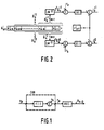
- Fig. 1 shows a functional discrete-time model of a system for transmitting data symbols a k at a symbol rate 1 T through a noisy dispersive channel CHN to a data receiver REC.
- the transmitted data signal a k is binary with a k e ⁇ -1, +1 ⁇ . This assumption is not meant to be restrictive.
- the invention is equally applicable to multilevel or complex-valued data signals, as encountered in e.g. digital voiceband communication systems.
- the channel CHN of Fig. 1 models the cascade of the actual continuous-time channel, a possible receiving filter and/or equalizer, and a synchronous sampling operation at the data rate 1/T.
- the discrete-time output signal r k of channel CHN can be described as where n k is a white Gaussian noise signal and f(.) is a deterministic function of a data vector where "' denotes transposition.
- the nonnegative integer M is referred to as the memory length of the channel.
- the receiver REC in Fig. 1 operates on r k in order to produce decisions â K-D about a delayed version a K-D of a k , where D is a nonnegative integer that is referred to as the detection delay.
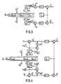
- Fig. 2 depicts a basic model of the likelihood calculations that are associated to any survivor s k in a receiver according to the above-mentioned prior art.
- a measure of accumulated likelihood Jk -1 is associated to the survivor s k -1 .
- this measure of accumulated likelihood will henceforth be referred to as a metric for the sake of compactness.
- the components are generated by linear weighing networks LW ij that operate on the M most recent digits of , and can be recognized as hypothesized channel output samples that would result on moment k if noise were absent and were transmitted.
- the metrics can be interpreted as accumulated Euclidean distances between the actual channel output signal r k and hypothesized channel output signals f . As time proceeds, the detector seeks to minimize this distance across all considered survivors.
- the detector compares the metrics J k J of the extended survivors for all i E ⁇ O,...N-1 ⁇ and j E ⁇ 0,1 ⁇ , and makes a selection on this basis.
- the details of this selection depend on the precise type of Viterbi detector, and will not be described here in further detail as they are immaterial to the invention.
- the outputs of the linear weighing networks LW ij can only serve as hypothesized channel outputs in the absence of noise for channels CHN that do not introduce nonlinear ISI. For this reason Viterbi detectors that conform to Fig. 2 are intrinsically unable to handle nonlinear ISI.
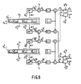
- Fig. 3 is identical to Fig. 2 except for look-up tables LUT ij that replace the linear weighing networks LW ij .
- Each table is addressed by a total of M + 1 binary data symbols and must therefore contain a total of 2 M+1 entries. Even for values of M as large as e.g. 10 this poses no instrumentational problems when use is made of currently available random access memories.
- Fig. 3 since possible outputs are directly looked up rather than calculated, the configuration of Fig. 3 will generally be easier to implement than that of Fig. 2. Furthermore, since look-up tables can store fully arbitrary input-output relations, the outputs h( â ) of LUT' i can serve as hypothesized channel outputs in the absence of noise by choosing In this way nonlinear ISI can be fully dealt with without increasing the complexity of the receiver. This compares favourably with a novel Viterbi detector that is described in said article by Mesiya et al.. This detector also distinguishes itself from Viterbi detectors according to the above-described prior art in that it can handle nonlinear ISI. However, for the Viterbi detector of Mesiya et al.
- the function h(.) as stored in the look-up tables LUT' i is updated recursively according to for all i E ⁇ 0,...,N-1 ⁇ and j ⁇ ⁇ 0,1 ⁇ .
- the new entries h ( ) are ideally improved estimates of f( ).
- the error signals indicate how well the hypothesized channel output signals in the absence of noise resemble the actual channel output signal, and the recursion of (9) seeks to minimize this difference iteratively.
- LMS adaptation algorithm that forms the basis for the recursion of (9) can be found, for example, in an article by P.J. van Gerwen, N.A.M.
- a disadvantage of the configuration of Fig. 4 is that very recent estimated data symbols play a role in the adaptation process. By nature of Viterbi detection, these symbols are less reliable estimated of the transmitted data signal than the older digits that also form part of the maintained survivors. More specifically, even if a given survivor has greatest current likelihood, its most recent digits (e.g. and ) may not coincide with the corresponding transmitted digits. Especially for functions f(.) with a weak dependence on these most recent transmitted digits this may in fact occur quite frequently. By (9) and (10) this would equally often cause erroneous table entries to be updated, a problem that may hamper or even preclude convergence of the table contents to the proper values.
- Fig. 5 A natural possibility to this end is outlined in Fig. 5.
- detection proceeds exactly as in Fig. 4, with the look-up tables LUT' i addressed by the estimated data vectors a .
- the switches are placed in the position "adapt”.
- the received signal r k is also delayed over P symbol intervals in order to form a delayed error signal which is used to update the look-up table LUT' J according to the LMS logarithm
- the data estimates used in this adaptation process are all relatively reliable, it is unnecessary in (14) to use selector signals to condition adaptation on current or past likelihood measures.
- FIG. 5 A disadvantage of the configuration of Fig. 5 is that each table is read out twice per symbol interval for calculation of error signals that play a role in detection and adaptation, respectively. Relative to Fig. 4, where these two functions are combined, this lowers the largest attainable data throughput. To overcome this problem it is possible to base adaptation on delayed versions of the error signals that were calculated for detection P symbol intervals earlier. This also makes it unnecessary to delay the received signal r k . A simplified version of this possibility will be described later.
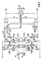
- Fig. 6 shows a conceptual model of a two-state Viterbi detector with linear feedback as described in the aforementioned article by Bergmans et al..
- the four extended survivors s for i,j e ⁇ 0,1 ⁇ are defined as in (5) and have metrics according to (6).
- Four linear weighing networks LW ij with i,j e ⁇ 0,1 ⁇ calculate the four possible weighted sums of eq. (6).
- the vecot f specifies the impulse response of the channel. This may be achieved, for example, with the help of adaptive techniques, as described in the aforementioned book by Proakis, chapter 6, pp. 410-412. Details of these techniques as applied in receivers of prior art are immaterial to the invention and therefore not discussed or shown here.
- any Viterbi detector it is desirable to have a detection delay D much greater than the channel memory length M, as explained, for example, in the aforementioned article by Forney.
- the oldest digits and are both comparatively reliable estimates of the transmitted digit a K-D a K-D .
- a disadvantage of the detector of Fig. 6 is that the metric values Jk are, by (6) and (15), a non-decreasing function of time in the usual case that the function G(.) is nonnegative definite. This may cause problems of overflow in a digital implementation of the detector. From (15) it can be noted that only differences between metrics play a role in the selection of new survivors. This observation may be used to re-normalize metric values in such a way that they are no longer a non-decreasing function of time. To this end, the modified metrics Q k , Q 0 K and Q 1 K are defined as and for i e ⁇ 0,1 ⁇ and all k.
- two shift registers SR 0 and SR' store the digits and of the survivors and , respectively.
- the selection can be realized with a SHIFT LEFT operation on shift register SR 0 .
- selector signals are such that only the table that corresponds to the most likely extended survivor is updated.
- selector signals are produced by a selector unit SEL that operates, for example, on the signals Q k , and according to the following truth table:
- any positive value of Q k indicates that the new survivor is more likely than its counterpart , and vice versa for a negative value of Q k .
- the signal can be used to this end, as it specifies, by eq. (22), exactly which of these two extended survivors forms .
- the signal specifies which of the two selector signals and is to be 1, while the other two selector signals are zero.
- the new value Q k is determined from the signals and according to eq. (20) by means of a summator, while a delay unit stores Q k for use during the next symbol interval. Furthermore, the oldest digit serves as the output â k . D of the receiver, as in Fig. 6. For the sake of brevity, further aspects of the receiver are not elaborated here as they are either sufficiently self-evident or sufficiently similar to aspects that were discussed before.
- the receiver of Fig. 7 is attractive in that it combines a complexity no greater than that of its linear counterpart of Fig. 6 with the ability to handle any form of linear or nonlinear ISI. Together with the receiver of Fig. 6, it shares the disadvantage that implementation may become difficult at very high data rates, as encountered in e.g. digital storage of video signals.
- One cause of this difficulty is that the formation of the signals G(ek' ) in Fig. 7 requires a table look-up operation, a subtraction and application of the function G, which together may require more time than is permissible.
- This feedback operation is the counterpart of the linear feedback operation that takes place in a more implicit manner in the conventional receiver of Fig. 7, as explained, for example, in the aforementioned article by Bergmans et al..
- As a consequence of this feedback operation only 4 out of the 8 possible vectors remain to be considered in the total of 4 adaptive precomputation units APU 00 ,...,APU 11 , as opposed to the 8 vectors that would have to be considered in a Viterbi detector without feedback.
- this simplification may be justified by noting that the digit . 2 that is fed back is the oldest and thus most reliable digit of the data vector under consideration. Thus the probability that an erroneous selection takes place in the circuit of Fig. is relatively small.
- Properties and conceptual backgrounds of Viterbi detectors with and without feedback are not elaborated here in further detail as they are well described in the literature, see e.g. the aforementioned article by Bergmans et al..
- the configuration of Fig. 8 includes a simplified version of the mechanism of Fig. 5 for adaptation of the counters C 0ij and C 1ij on the basis of delayed digits
- the mechanism of Fig. 5 is preferable over the one of Figs. 4 and Fig. 7 in that it lowers convergence problems for functions f( a k ) with a weak dependence on the most recent digits of a k , such as a k and a k . l .
- Said simplification stems from a sign operation that is performed on the error signals and to obtain one-bit error signals that are conveniently handled with digital circuitry.
- a switch SW e with a feedback function similar to that of SW 9 is controlled by ak .
- the delayed error signal sgn( p) is by (1) a function of the delayed data vector a k .p.
- Alternative rules in which both vectors and are used for the formation of essentially equivalent selector signal signals are, of course, equally suitable but are not described here for the sake of brevity.
- Fig. 8 In the configuration of Fig. 8, the signals and sgn( ) are connected to the COUNT ENABLE and UP/DOWN inputs of counters C 1ij in order to realize the iteration of (24). Depending on such implementation details as the type of counters used, slight modifications of the configuration of Fig. 8 may be needed to realize the iteration of eq. (24) in a convenient manner. In this respect Fig. 8 is merely illustrative, and is not meant to restrict in any sense the use of the sign-algorithm as described above.
- Fig. 8 can be easily modified for use of the LMS rather than sign-algorithm by omitting the Sign-operations in Fig. 1.
- the counters of Fig. 8 should then be replaced by digital accumulators that store and can be updated in steps q. that may assume a multitude of sizes.
- Intermediate forms of the LMS and sign algorithms arise when such an accumulator is used in combination with a multi-bit quantizer instead of the sign operation in Fig. 8.
- u or q can be variable rather than fixed. For example, for rapid convergence it is attractive to start adaptation with a relatively large value of u or q. Subsequently, u or q may be decreased gradually or step-wise to a value that is appropriate for small steady-state adaptation errors.
- Fig. 8 is meant to be illustrative rather than restrictive.
- Fig. 9 depicts a model of a two-state Viterbi detector according to the invention in which the precomputation units of Fig. 8 are applied.
- the detector of Fig. 9 rather distinguishes itself from the one of Fig. 7 in that it employs a faster method of calculating Q k .
- calculation of Q k can not start before the selection process in compare/select units CS° and CS' is completed.
- the complete receiver according to Figs. 8 and 9 may be implemented with approximately 80 digital integrated circuits from the standard ECL 100K series as described, for example, in the "F100K ECL data book", Fairchild Camera and Instrument Corporation, Mountain View, California, 1982.
- internal signals of the receiver are represented with a word-length of at most 6 bits.
- the attainable data rate amounts to approximately 50 Mbit/s. Even for digital video storage applications this may be an appropriate value.
- the nonlinearities arise from a systematic difference in the length of the pits and lands that represent runs of zeros and ones.
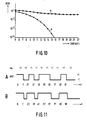
- the curves of Fig. 10 pertain to a situation with severe nonlinear ISI, in which systematic errors in the writing process cause runs of zeros and ones to be T/2 seconds shorter and longer than their nominal value, respectively.
- Fig. 11 This situation is illustrated in Fig. 11.
- the upper trace A depicts the NRZ waveform that is applied to the channel
- the lower trace B depicts the corresponding pattern of pits and lands that is assumed to be recorded on the optical medium.
- the systematic difference in the lengths of pits and lands manifests itself in the replayed signal as severe nonlinear ISI.
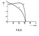
- the replayed signal is taken to contain linear ISI as a result of the channel bandwidth limitations that are reflected in Fig. 12.
- the curve that is labeled C in Fig. 12 depicts the transfer characteristic of the linear part of the channel.
- the loss of around 20 dB at the Nyquist frequency 1/(2T) is characteristic for recording at high information densities, and results in severe linear ISI in the replay signal.
- an equalizer operating on the replayed signal is used to shorten the memory length of the channel into a memory length M of approximately 2 symbol intervals. Techniques for designing this equalizer are not discussed here as they are well described in the literature, see e.g. an article by D.D. Falconer and F.R.
- Fig. 10 confirms the superiority of the receiver according to the invention (curve b.) over its conventional counterpart (curve a.) in dealing with nonlinear ISI. While the former receiver is unable to achieve useful performance levels even at very high signal-to-noise ratio's, the latter one already achieves bit error rates of around 10- 4 for signal-to-noise ratio's of about 16 dB. Additional simulations reveal that this represents a loss of only 3 to 4 dB with respect to a corresponding situation without nonlinearities. Thus a receiver according to the invention may provide an attractive degree of insensitivity to nonlinear ISI, unlike its predecessors of prior art.
Landscapes
- Engineering & Computer Science (AREA)
- Computer Networks & Wireless Communication (AREA)
- Signal Processing (AREA)
- Physics & Mathematics (AREA)
- Optics & Photonics (AREA)
- Power Engineering (AREA)
- Error Detection And Correction (AREA)
- Dc Digital Transmission (AREA)
- Detection And Prevention Of Errors In Transmission (AREA)
Applications Claiming Priority (2)
| Application Number | Priority Date | Filing Date | Title |
|---|---|---|---|
| JP160756/89 | 1989-06-26 | ||
| JP1160756A JP2960436B2 (ja) | 1989-06-26 | 1989-06-26 | 非線形データ伝送システム用受信器 |
Publications (3)
| Publication Number | Publication Date |
|---|---|
| EP0405662A2 true EP0405662A2 (fr) | 1991-01-02 |
| EP0405662A3 EP0405662A3 (en) | 1992-02-26 |
| EP0405662B1 EP0405662B1 (fr) | 1996-02-21 |
Family
ID=15721788
Family Applications (1)
| Application Number | Title | Priority Date | Filing Date |
|---|---|---|---|
| EP90201631A Expired - Lifetime EP0405662B1 (fr) | 1989-06-26 | 1990-06-21 | Récepteur pour système de transmission de données avec non-linéarités |
Country Status (6)
| Country | Link |
|---|---|
| US (1) | US5131011A (fr) |
| EP (1) | EP0405662B1 (fr) |
| JP (1) | JP2960436B2 (fr) |
| KR (1) | KR0152662B1 (fr) |
| CA (1) | CA2019659C (fr) |
| DE (1) | DE69025433T2 (fr) |
Cited By (3)
| Publication number | Priority date | Publication date | Assignee | Title |
|---|---|---|---|---|
| WO1992016065A1 (fr) * | 1991-03-11 | 1992-09-17 | British Telecommunications Public Limited Company | Detection de rafales d'erreurs |
| EP0585095A3 (en) * | 1992-08-26 | 1995-09-13 | Sony Corp | Signal processing system having intersymbol-interference cancelling means and method of same |
| EP2048808A3 (fr) * | 2007-10-10 | 2014-08-06 | Sony Corporation | Dispositif de réception, procédé de réception, dispositif de traitement des informations, procédé de traitement des informations et programme |
Families Citing this family (32)
| Publication number | Priority date | Publication date | Assignee | Title |
|---|---|---|---|---|
| DE69223438T2 (de) * | 1991-04-24 | 1998-06-04 | Koninkl Philips Electronics Nv | Abtasttaktrückwinnung für Empfänger, die Viterbi-Verarbeitung benutzen |
| MY108838A (en) * | 1992-07-03 | 1996-11-30 | Koninklijke Philips Electronics Nv | Adaptive viterbi detector |
| US5408503A (en) * | 1992-07-03 | 1995-04-18 | U.S. Philips Corporation | Adaptive viterbi detector |
| US5463654A (en) * | 1992-08-03 | 1995-10-31 | U.S. Philips Corporation | Transmission system with increased sampling rate detection |
| US5430744A (en) * | 1993-09-30 | 1995-07-04 | International Business Machines Corporation | Method and means for detecting partial response waveforms using a modified dynamic programming heuristic |
| FI107420B (fi) * | 1994-04-18 | 2001-07-31 | Nokia Networks Oy | Vastaanottomenetelmä ja vastaanotin |
| US5542458A (en) * | 1994-08-22 | 1996-08-06 | Gilbarco Inc. | Vapor recovery system for a fuel delivery system |
| US5557645A (en) * | 1994-09-14 | 1996-09-17 | Ericsson-Ge Mobile Communications Inc. | Channel-independent equalizer device |
| US6393598B1 (en) | 1995-04-20 | 2002-05-21 | Seagate Technology Llc | Branch metric compensation for digital sequence detection |
| US6091765A (en) * | 1997-11-03 | 2000-07-18 | Harris Corporation | Reconfigurable radio system architecture |
| US6381271B1 (en) | 1998-08-17 | 2002-04-30 | Telefonaktiebolaget Lm Ericsson (Publ) | Low complexity decision feedback sequence estimation |
| US7099410B1 (en) | 1999-01-26 | 2006-08-29 | Ericsson Inc. | Reduced complexity MLSE equalizer for M-ary modulated signals |
| US6928161B1 (en) * | 2000-05-31 | 2005-08-09 | Intel Corporation | Echo cancellation apparatus, systems, and methods |
| US7006800B1 (en) * | 2003-06-05 | 2006-02-28 | National Semiconductor Corporation | Signal-to-noise ratio (SNR) estimator in wireless fading channels |
| JP2005166221A (ja) * | 2003-12-05 | 2005-06-23 | Canon Inc | 情報再生方法及び情報再生装置 |
| US7653154B2 (en) * | 2004-05-25 | 2010-01-26 | Agere Systems Inc. | Method and apparatus for precomputation and pipelined selection of intersymbol interference estimates in a reduced-state Viterbi detector |
| KR100791568B1 (ko) * | 2007-03-26 | 2008-01-03 | 전태구 | 축압식 소화기 |
| US8225252B2 (en) * | 2010-06-25 | 2012-07-17 | Intel Corporation | Systems, methods, apparatus and computer readable mediums for use in association with systems having interference |
| US8572458B1 (en) | 2012-06-20 | 2013-10-29 | MagnaCom Ltd. | Forward error correction with parity check encoding for use in low complexity highly-spectrally efficient communications |
| US9166834B2 (en) | 2012-06-20 | 2015-10-20 | MagnaCom Ltd. | Method and system for corrupt symbol handling for providing high reliability sequences |
| US8781008B2 (en) | 2012-06-20 | 2014-07-15 | MagnaCom Ltd. | Highly-spectrally-efficient transmission using orthogonal frequency division multiplexing |
| US8737458B2 (en) | 2012-06-20 | 2014-05-27 | MagnaCom Ltd. | Highly-spectrally-efficient reception using orthogonal frequency division multiplexing |
| US9088400B2 (en) | 2012-11-14 | 2015-07-21 | MagnaCom Ltd. | Hypotheses generation based on multidimensional slicing |
| US8811548B2 (en) | 2012-11-14 | 2014-08-19 | MagnaCom, Ltd. | Hypotheses generation based on multidimensional slicing |
| US9118519B2 (en) | 2013-11-01 | 2015-08-25 | MagnaCom Ltd. | Reception of inter-symbol-correlated signals using symbol-by-symbol soft-output demodulator |
| US8804879B1 (en) | 2013-11-13 | 2014-08-12 | MagnaCom Ltd. | Hypotheses generation based on multidimensional slicing |
| US9130637B2 (en) | 2014-01-21 | 2015-09-08 | MagnaCom Ltd. | Communication methods and systems for nonlinear multi-user environments |
| US9496900B2 (en) | 2014-05-06 | 2016-11-15 | MagnaCom Ltd. | Signal acquisition in a multimode environment |
| US8891701B1 (en) | 2014-06-06 | 2014-11-18 | MagnaCom Ltd. | Nonlinearity compensation for reception of OFDM signals |
| US9246523B1 (en) | 2014-08-27 | 2016-01-26 | MagnaCom Ltd. | Transmitter signal shaping |
| US9276619B1 (en) | 2014-12-08 | 2016-03-01 | MagnaCom Ltd. | Dynamic configuration of modulation and demodulation |
| US9191247B1 (en) | 2014-12-09 | 2015-11-17 | MagnaCom Ltd. | High-performance sequence estimation system and method of operation |
Family Cites Families (8)
| Publication number | Priority date | Publication date | Assignee | Title |
|---|---|---|---|---|
| US4015238A (en) * | 1975-11-24 | 1977-03-29 | Harris Corporation | Metric updater for maximum likelihood decoder |
| US4163209A (en) * | 1977-09-28 | 1979-07-31 | Harris Corporation | Technique for controlling memoryful non-linearities |
| US4564952A (en) * | 1983-12-08 | 1986-01-14 | At&T Bell Laboratories | Compensation of filter symbol interference by adaptive estimation of received symbol sequences |
| ATE35755T1 (de) * | 1984-05-08 | 1988-07-15 | Siemens Ag | Codefehlereinblendung in digitale uebertragungssignale. |
| NL8700125A (nl) * | 1987-01-20 | 1988-08-16 | Philips Nv | Inrichting voor het bestrijden van intersymboolinterferentie en ruis. |
| US4733402A (en) * | 1987-04-23 | 1988-03-22 | Signatron, Inc. | Adaptive filter equalizer systems |
| US4885757A (en) * | 1987-06-01 | 1989-12-05 | Texas Instruments Incorporated | Digital adaptive receiver employing maximum-likelihood sequence estimation with neural networks |
| NL8701333A (nl) * | 1987-06-09 | 1989-01-02 | Philips Nv | Inrichting voor het bestrijden van intersymboolinterferentie en ruis. |
-
1989
- 1989-06-26 JP JP1160756A patent/JP2960436B2/ja not_active Expired - Fee Related
-
1990
- 1990-06-21 EP EP90201631A patent/EP0405662B1/fr not_active Expired - Lifetime
- 1990-06-21 DE DE69025433T patent/DE69025433T2/de not_active Expired - Fee Related
- 1990-06-22 CA CA002019659A patent/CA2019659C/fr not_active Expired - Fee Related
- 1990-06-26 KR KR1019900009634A patent/KR0152662B1/ko not_active Expired - Fee Related
- 1990-06-26 US US07/545,308 patent/US5131011A/en not_active Expired - Lifetime
Cited By (4)
| Publication number | Priority date | Publication date | Assignee | Title |
|---|---|---|---|---|
| WO1992016065A1 (fr) * | 1991-03-11 | 1992-09-17 | British Telecommunications Public Limited Company | Detection de rafales d'erreurs |
| US5416788A (en) * | 1991-03-11 | 1995-05-16 | British Telecommunications Public Limited Company | Error burst detection |
| EP0585095A3 (en) * | 1992-08-26 | 1995-09-13 | Sony Corp | Signal processing system having intersymbol-interference cancelling means and method of same |
| EP2048808A3 (fr) * | 2007-10-10 | 2014-08-06 | Sony Corporation | Dispositif de réception, procédé de réception, dispositif de traitement des informations, procédé de traitement des informations et programme |
Also Published As
| Publication number | Publication date |
|---|---|
| KR910002173A (ko) | 1991-01-31 |
| CA2019659A1 (fr) | 1990-12-26 |
| JP2960436B2 (ja) | 1999-10-06 |
| DE69025433D1 (de) | 1996-03-28 |
| DE69025433T2 (de) | 1996-09-12 |
| US5131011A (en) | 1992-07-14 |
| KR0152662B1 (ko) | 1998-11-02 |
| EP0405662B1 (fr) | 1996-02-21 |
| EP0405662A3 (en) | 1992-02-26 |
| CA2019659C (fr) | 1999-10-26 |
| JPH0327647A (ja) | 1991-02-06 |
Similar Documents
| Publication | Publication Date | Title |
|---|---|---|
| US5131011A (en) | Receiver for data transmission system with nonlinearities | |
| EP0133480B1 (fr) | Procédé et dispositif pour décoder le signal sortant d'un canal de communication ou d'un dispositif d'enregistrement à réponse partielle | |
| US5784415A (en) | Adaptive noise-predictive partial-response equalization for channels with spectral nulls | |
| US6711213B2 (en) | Implementing reduced-state viterbi detectors | |
| Forney | Maximum-likelihood sequence estimation of digital sequences in the presence of intersymbol interference | |
| US5325402A (en) | Method and arrangement for estimating data sequences transmsitted using Viterbi algorithm | |
| JP4904276B2 (ja) | ローカル帰還のある低減状態ビタビ検出器内のパイプライン化判定帰還ユニット | |
| US5917859A (en) | Method and apparatus for implementing a viterbi detector for PRML channels | |
| Xiong et al. | Sequential sequence estimation for channels with intersymbol interference of finite or infinite length | |
| US5892801A (en) | Decision path reduction of M-ary tree-search detector | |
| Moon et al. | Efficient sequence detection for intersymbol interference channels with run-length constraints | |
| EP0577212A1 (fr) | Détecteur Viterbi adaptif | |
| EP0380172B1 (fr) | Système de transmission de signal de données binaire | |
| US6163517A (en) | Signal detection method of data recording/reproducing apparatus and device therefor | |
| US6219388B1 (en) | Digital data demodulating device for estimating channel impulse response | |
| CN111566953A (zh) | 符号判定装置和符号判定方法 | |
| Vermeulen | Low complexity decoders for channels with intersymbol interference. | |
| JPH0671275B2 (ja) | ディジタル符号復号装置 | |
| Zayed et al. | Generalized partial response signalling and efficient MLSD using linear Viterbi branch metrics | |
| JP2551296B2 (ja) | 系列推定装置 | |
| JPH0715355A (ja) | 等化・復号装置 | |
| JP2625831B2 (ja) | 復号装置 | |
| WO2024061266A1 (fr) | Procédé de mise en œuvre d'égaliseur mlse, puce, dispositif électronique, et support lisible par ordinateur | |
| JP2764910B2 (ja) | 等化・復号装置 | |
| Hwang et al. | Partial response equalization with nonlinearity-compensating signal asymmetry in DVD storage |
Legal Events
| Date | Code | Title | Description |
|---|---|---|---|
| PUAI | Public reference made under article 153(3) epc to a published international application that has entered the european phase |
Free format text: ORIGINAL CODE: 0009012 |
|
| AK | Designated contracting states |
Kind code of ref document: A2 Designated state(s): DE FR GB IT NL |
|
| PUAL | Search report despatched |
Free format text: ORIGINAL CODE: 0009013 |
|
| AK | Designated contracting states |
Kind code of ref document: A3 Designated state(s): DE FR GB IT NL |
|
| 17P | Request for examination filed |
Effective date: 19920727 |
|
| 17Q | First examination report despatched |
Effective date: 19940621 |
|
| GRAH | Despatch of communication of intention to grant a patent |
Free format text: ORIGINAL CODE: EPIDOS IGRA |
|
| GRAA | (expected) grant |
Free format text: ORIGINAL CODE: 0009210 |
|
| AK | Designated contracting states |
Kind code of ref document: B1 Designated state(s): DE FR GB IT NL |
|
| REF | Corresponds to: |
Ref document number: 69025433 Country of ref document: DE Date of ref document: 19960328 |
|
| ITF | It: translation for a ep patent filed | ||
| ET | Fr: translation filed | ||
| PLBE | No opposition filed within time limit |
Free format text: ORIGINAL CODE: 0009261 |
|
| STAA | Information on the status of an ep patent application or granted ep patent |
Free format text: STATUS: NO OPPOSITION FILED WITHIN TIME LIMIT |
|
| 26N | No opposition filed | ||
| NLT1 | Nl: modifications of names registered in virtue of documents presented to the patent office pursuant to art. 16 a, paragraph 1 |
Owner name: KONINKLIJKE PHILIPS ELECTRONICS N.V.;HITACHI, LTD. |
|
| REG | Reference to a national code |
Ref country code: FR Ref legal event code: CD |
|
| REG | Reference to a national code |
Ref country code: GB Ref legal event code: IF02 |
|
| PGFP | Annual fee paid to national office [announced via postgrant information from national office to epo] |
Ref country code: NL Payment date: 20040625 Year of fee payment: 15 |
|
| PGFP | Annual fee paid to national office [announced via postgrant information from national office to epo] |
Ref country code: FR Payment date: 20040628 Year of fee payment: 15 |
|
| PGFP | Annual fee paid to national office [announced via postgrant information from national office to epo] |
Ref country code: GB Payment date: 20040629 Year of fee payment: 15 |
|
| PGFP | Annual fee paid to national office [announced via postgrant information from national office to epo] |
Ref country code: DE Payment date: 20040813 Year of fee payment: 15 |
|
| PG25 | Lapsed in a contracting state [announced via postgrant information from national office to epo] |
Ref country code: IT Free format text: LAPSE BECAUSE OF NON-PAYMENT OF DUE FEES Effective date: 20050621 Ref country code: GB Free format text: LAPSE BECAUSE OF NON-PAYMENT OF DUE FEES Effective date: 20050621 |
|
| PG25 | Lapsed in a contracting state [announced via postgrant information from national office to epo] |
Ref country code: NL Free format text: LAPSE BECAUSE OF NON-PAYMENT OF DUE FEES Effective date: 20060101 |
|
| PG25 | Lapsed in a contracting state [announced via postgrant information from national office to epo] |
Ref country code: DE Free format text: LAPSE BECAUSE OF NON-PAYMENT OF DUE FEES Effective date: 20060103 |
|
| PG25 | Lapsed in a contracting state [announced via postgrant information from national office to epo] |
Ref country code: FR Free format text: LAPSE BECAUSE OF NON-PAYMENT OF DUE FEES Effective date: 20060228 |
|
| GBPC | Gb: european patent ceased through non-payment of renewal fee |
Effective date: 20050621 |
|
| NLV4 | Nl: lapsed or anulled due to non-payment of the annual fee |
Effective date: 20060101 |
|
| REG | Reference to a national code |
Ref country code: FR Ref legal event code: ST Effective date: 20060228 |