EP0406207A1 - Métier à tisser avec verrouillage - Google Patents
Métier à tisser avec verrouillage Download PDFInfo
- Publication number
- EP0406207A1 EP0406207A1 EP90870090A EP90870090A EP0406207A1 EP 0406207 A1 EP0406207 A1 EP 0406207A1 EP 90870090 A EP90870090 A EP 90870090A EP 90870090 A EP90870090 A EP 90870090A EP 0406207 A1 EP0406207 A1 EP 0406207A1
- Authority
- EP
- European Patent Office
- Prior art keywords
- weaving machine
- lock
- hand wheel
- machine according
- locking element
- Prior art date
- Legal status (The legal status is an assumption and is not a legal conclusion. Google has not performed a legal analysis and makes no representation as to the accuracy of the status listed.)
- Withdrawn
Links
Images


Classifications
-
- D—TEXTILES; PAPER
- D03—WEAVING
- D03D—WOVEN FABRICS; METHODS OF WEAVING; LOOMS
- D03D51/00—Driving, starting, or stopping arrangements; Automatic stop motions
-
- D—TEXTILES; PAPER
- D03—WEAVING
- D03D—WOVEN FABRICS; METHODS OF WEAVING; LOOMS
- D03D51/00—Driving, starting, or stopping arrangements; Automatic stop motions
- D03D51/005—Independent drive motors
-
- D—TEXTILES; PAPER
- D03—WEAVING
- D03D—WOVEN FABRICS; METHODS OF WEAVING; LOOMS
- D03D51/00—Driving, starting, or stopping arrangements; Automatic stop motions
- D03D51/02—General arrangements of driving mechanism
Definitions
- This invention concerns a weaving machine, in particular a weaving machine with a lock.
- harness motion can be obtained by means of a positive or negative drive.
- a negative drive moves the harness frames in one direction through cams, and in the other direction through springs which ensure the contact with the cams.
- the harness drive is coupled to the main shaft of the weaving machine.
- the main shaft of the weaving machine can be equipped with an electromagnetic brake, which is activated by electric energization. When the weaving machine stops, this brake is energized.
- the brake In the case of weaving machines with a negative harness drive, it is clear that the brake must also receive a couple at standstill, namely the couple exercized by the springs of the harness frames on the harness drive and therefore also on the main shaft. The intensity and direction of this couple depend of course on the position of the main shaft and the position of the various harnesses.
- said weaving machines are usually equipped with capacitors which ensure the energization of the electromagnetic brake for a period of time after the mains voltage has failed. This period is usually insufficient to do normal repair work on a weft thread or warp thread.
- the brake is previously uncoupled, so that a state of equilibrium is reached.
- the disadvantage is, however, that at the start of the weaving machine, the various weaving machine parts are not any longer in their optimum position to avoid starting marks and suchlike.
- an electromagnetic brake is used, whereby the brake force is obtained under the influence of a spring force, and whereby the deactivation of this brake is done by energizing the electromagnet, such that the brake is opened against the spring force.
- This brake has the disadvantage that a large amount of energy is required during the normal operation of the weaving machine.
- Such a brake also has the disadvantage that, during a standstill, the weaving machine is entirely blocked and that a rotation by means of the hand wheel is no more possible, unless a special device is provided with the aim of deactivating this brake manually.
- the above-mentioned problem occurs less frequently on weaving machines with a positive harness drive.
- a positive harness drive the movement of the harness frames in both directions is exclusively obtained by means of cam guides.
- the weaving machine stops a considerable couple may occur when the largest number of harnesses are in their highest position, while only a few harness frames are in their lowest position. Indeed, in that case it is possible that the weaving machine is set in motion due to the weight of the lifted harness frames or due to the tension in the warp threads.
- the present invention concerns a weaving machine, whereby a solution is offered to the above-mentioned problem, however without the above-mentioned disadvantages of the known devices occur.
- the invention concerns a weaving machine of the type whereby the main shaft is provided with an electromagnetic brake which is activated by means of electric energization, characterized in that the weaving machine has, apart from the above-mentioned brake, a lock with which the main shaft can be directly or indirectly locked against rotation, and which consists of a locking element which can mesh into a wheel which is coupled to the main shaft and which is equipped with gear teeth.
- the weaving machine also has means which automatically activate the lock when the mains voltage of the weaving machine fails.
- the weaving machine according to the invention also has a hand wheel as well as means which allow the above-mentioned lock to be deactivated when this hand wheel is operated.
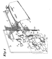
- fig. 1 shows a schematic representation of a weaving machine, with as its main parts the warp beam 1, the warp 2, the formed cloth 3, the cloth beam 4, the harness frames 5, the shed 6 formed by the harness frames, the sley 7 with the reed 8 and supply means 9 for the supply of weft threads 10.
- the drive of the weaving machine is by means of the main drive motor 11 which can be coupled to the main shaft 12, which in turn provides the movement of the sley 7 by means of the cam drive 13.
- the main shaft 12 is, for example by means of gears 14 and 15 and an intermediate gear 16, coupled to the drive shaft 17 of the harness drive mechanism 18, which has a known cam mechanism, of which the movement is transferred to the harness frames 5 by means of transfer means 19, such as cables.
- the upward movement is obtained by means of the harness drive mechanism 18, while the force for moving the harness frames 5 downward is provided by springs 20.
- the main drive motor 11 can be coupled to the main shaft 12 by means of a unit 21, which, as shown in fig. 2, consists of a transfer 22, for example a belt transfer; a flywheel 23 which is driven by the transfer 22; an electromagnetic clutch 24 which allows the main shaft 12 to be coupled to the flywheel 23, and an electromagnetic brake 25 which allows to brake the main shaft 12.
- a unit 21 which, as shown in fig. 2, consists of a transfer 22, for example a belt transfer; a flywheel 23 which is driven by the transfer 22; an electromagnetic clutch 24 which allows the main shaft 12 to be coupled to the flywheel 23, and an electromagnetic brake 25 which allows to brake the main shaft 12.
- an axially movable clutch disc 26 can be used, which is rotatable with the main shaft 12 and which on the one hand can operate in conjunction with a clutch disc 27, rotatable with the flywheel 23, and on the other hand with a fixed brake disc 28.
- the clutch and the brake can be energized by windings 29 and 30 respectively.
- the drive shaft 17 is coupled to the gear 15 by means of a pick find clutch 31, for example of the type as described in USA patent No. 4.592.392 of the applicant.
- This pick find clutch 31 essentially consists of a central clutching part 32, fixed to the drive shaft 17; a clutching part 33 which rotates with the entering shaft 34; and a clutching part 35 which can be driven by means of a slow motion motor 36.
- the clutching parts 33 and can be moved axially by means of electromagnets 37 and 38, as well as by springs 39 and 40, such that they can be coupled to the central clutching part 32 as desired. In a state of rest, the clutching part 33 is always coupled to the central clutching part 32 by means of the springs 39, such that in a state of rest, the main shaft 12 is also coupled to the drive shaft 17.
- main drive motor 11, the harness drive mechanism 18, the unit 21, the pick find clutch 31 and the slow motion motor 36 are fixed, in other words they are attached to the frame of the weaving machine.
- the clutch 24 is uncoupled and the brake 25 is activated by energizing the electromagnet 30.
- the weaving machine according to the present invention is equipped with a lock 41, by means of which the main shaft 12 and also, coupled to said main shaft 12, the drive shaft 17 of the harness drive mechanism 18 can be locked against rotation.
- this lock 41 is mounted on the above-mentioned intermediate gear 16, as shown in figs. 1 and 3.
- a wheel 42 with rectangular gear teeth 43 is applied to the intermediate gear 16, as shown in fig. 3.
- a locking element 44 is mounted which can mesh into the gear teeth 43, which preferably makes up part of a lever 45 which is rotatable round a pivot 46.
- the lever In the unlocked position, the lever, as indicated by reference 45A, is held by a permanent magnet 47 or any other type of holding mechanism.
- the lock can be activated by releasing the lever 45 from the permanent magnet 47. According to fig. 3, this is obtained by energizing a solenoid 48, which neutralizes the magnetic field of the permanent magnet 47, such that the lever 45, particularly the locking element 44, is drawn against the wheel 42 by means of a spring 49 or other elastic means, and meshes into the gear teeth 43.
- a solenoid 48 which neutralizes the magnetic field of the permanent magnet 47, such that the lever 45, particularly the locking element 44, is drawn against the wheel 42 by means of a spring 49 or other elastic means, and meshes into the gear teeth 43.
- other means can be used to activate the lock, or that the lock can also be activated under its own weight.
- Such locks have the advantage that they remain activated without any particular means, up to the moment when the lock is deactivated.
- Deactivating the lock can be done in various ways. According to a first possibility, it can be done manually, for example by means of a handle 50 on the lever 45. According to another possibility, the lever 45 can be connected with a foot-operation.
- the lock can be deactivated by activating an electromagnetic or pneumatic control mechanism 51, which acts on the bottom end of the lever 45.
- the electromagnetic control mechanism 51, the permanent magnet 47 and the solenoid 48 can be integrated in a unit.
- the working is analogous as mentioned above and consists in that, in the unlocked position, the lever 45 is held by the permanent magnet 47, the lock is activated by energizing the solenoid 48, such that the latter neutralizes the magnetic field of the permanent magnet 47, resulting in the lever 45 being drawn against the wheel 42 by means of a spring 49, and the lock being deactivated by switching the polarity of the voltage at the solenoid 48, such that the magnetic field of the solenoid 48 reinforces the magnetic field of the permanent magnet 47, and the lever 45 is drawn against the permanent magnet 47 against the force of the spring 49. It is clear that in this case the necessary means must be provided to switch the polarity of the voltage at the solenoid.
- the weaving machine can be slightly turned, either manually by the hand-operation or automatically by activating the slow motion motor 36 until the locking element 44 is released from the gear teeth 43.
- the weaving machine also has means which automatically activate the lock 41 when the mains voltage fails, as well as means which, when the weaving machine is still working, first provide an automatic brake before the locking element 44 is activated.
- all these means consist of a voltage meter 53 and capacitor supply 54, both connected to the electric mains line 52, a detector 55 for observing the rotation of the main shaft 12, switching means 56 between the capacitor supply 54 and the windings 30 of the brake 25, switching means 57 between the capacitor supply 54 and the above-mentioned solenoid 48 or similar, and a unit 58 which can make up part of the general control 59 of the weaving machine, which couples the above-mentioned parts and controls them.
- the capacitor supply 54 any kind of separate power supply can be used.
- the unit 58 first activates the switching element 56, such that the electromagnetic brake 25 is energized from the charged capacitor supply 54. From the moment when the detector 55 no longer observes a rotation of the main shaft 12, switching element 57 is also closed, such that the solenoid 48 is energized by means of a signal A, the magnetic field of the permanent magnet 47 is neutralized and the lock 41 is activated, after which the weaver can safely work on the weaving machine.
- lock 41 can also be deactivated automatically, for example by coupling the control mechanism 51 to the control 59, such that the control mechanism 51 can be energized automatically by means of a signal B when the weaving machine is started.
- the hand wheel 60 of the weaving machine and the above-mentioned lock 41 can operate in conjunction with one another, whereby means 61 are provided which allow the activation and deactivation of the lock 41 by means of the hand wheel.
- means 61 are provided which allow the activation and deactivation of the lock 41 by means of the hand wheel.
- on the one hand means 62 are used for coupling and uncoupling the hand wheel 60 with the weaving machine, and on the other hand means 63 are used for breaking the lock 41, whereby these means 62 and 63 operate in conjunction with one another so that the lock 41 is automatically released when the hand wheel is activated.
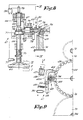
- the above-mentioned means are preferably made so that the hand wheel 60 can be set in three positions, as described by means of figs. 5 to 9.
- the means 62 for coupling and uncoupling the hand wheel 60 essentially consist of a shaft 64 with a grooved end 65, which can be shifted in a conical gear 66, a second conical gear 67 operating in conjunction with it, which in turn operates in conjunction with a grooved shaft 68 shiftable inside it, a gear 69 fixed on the shaft which as a result of the axial shift of the shaft 68 can mesh into a gear which is coupled to the main shaft, preferably into the above-mentioned intermediate gear 16, and a moving mechanism to move the shaft 68 when the hand wheel 60 is activated.
- This moving mechanism essentially ensures that the hand wheel 60 can be moved axially with the shaft 64, against the force of the spring 70, whereby a conical guide 71, connected with the shaft 64, acts on the end 72 of said shaft 68.
- a spring 73 ensures in this case the permanent contact between the end 72 and the conical guide 71.
- the means 63 which can break the lock 41 essentially consist of a widening, preferably conical element 74, which is shiftable over the shaft 68 against the force of the compression spring 75, and whose side comes in contact with the lever 45 due to this shift, as shown in fig. 6, such that said lever 45 can be pushed out of its locked position.
- Figs. 5 and 6 show a position whereby the hand wheel 60 is deactivated.
- the conical element 74 is pushed against a stop 76 in this case.
- the gear 69 meshes into the intermediate gear 16.
- this locking element 44 will be jammed in the wheel 42, resulting in the conical element 74 being stopped by the lever 45.
- the locking element 44 is released and the element 74 is moved by means of the spring 75, up to a position as shown in fig. 8, particularly up to the stop 76.
- the lever 45 takes in this case a position as indicated by the full line in fig. 9, whereby it is not yet attracted by the permanent magnet 47. This means that when the hand wheel is released again, the whole retakes a position as indicated in fig. 7. However, when the hand wheel 60 is pressed further, up to position III, the lever 45 comes in contact with the permanent magnet 47, resulting in the lock 41 remaining definitely broken until the solenoid 48 is energized again.
- the whole can be equipped with various detection elements, such as proximity switches 77 to 80, connected with the general control 59 in order to execute various control functions.
- the proximity switch 77 allows, for example, to observe the pressing of the hand wheel 60 such that when in that case the weaving machine is still running, it is automatically stopped.
- the proximity switch 78 observes the pressing of the shaft 64 and ensures that the electromagnetic brake 25 is uncoupled, such that the turning of the machine is made possible by means of the hand wheel 60.
- the proximity switches 79 and 80 control the position of the element 74 and the lever 45 respectively.
Landscapes
- Engineering & Computer Science (AREA)
- Textile Engineering (AREA)
- Looms (AREA)
- Braking Arrangements (AREA)
Applications Claiming Priority (2)
| Application Number | Priority Date | Filing Date | Title |
|---|---|---|---|
| BE8900716A BE1004064A3 (nl) | 1989-06-29 | 1989-06-29 | Weefmachine met vergrendeling. |
| BE8900716 | 1989-06-29 |
Publications (1)
| Publication Number | Publication Date |
|---|---|
| EP0406207A1 true EP0406207A1 (fr) | 1991-01-02 |
Family
ID=3884231
Family Applications (1)
| Application Number | Title | Priority Date | Filing Date |
|---|---|---|---|
| EP90870090A Withdrawn EP0406207A1 (fr) | 1989-06-29 | 1990-06-13 | Métier à tisser avec verrouillage |
Country Status (4)
| Country | Link |
|---|---|
| US (1) | US5046534A (fr) |
| EP (1) | EP0406207A1 (fr) |
| JP (1) | JPH0340842A (fr) |
| BE (1) | BE1004064A3 (fr) |
Cited By (1)
| Publication number | Priority date | Publication date | Assignee | Title |
|---|---|---|---|---|
| EP1245707A1 (fr) * | 2001-03-29 | 2002-10-02 | Promatech S.p.A. | Embrayage multiposition avec système de blocage de l'élément mobile dans un dispositif d'entraínement de métier à tisser |
Families Citing this family (8)
| Publication number | Priority date | Publication date | Assignee | Title |
|---|---|---|---|---|
| JP3704759B2 (ja) * | 1995-08-23 | 2005-10-12 | 株式会社豊田自動織機 | 織機の開口装置における綜絖枠高さ位置保持方法及び装置 |
| DE19813521A1 (de) * | 1998-03-26 | 1999-09-30 | Bauer Spezialtiefbau | Drehkranzbremse |
| DE102006031508A1 (de) * | 2006-07-07 | 2008-01-17 | Robert Bosch Gmbh | Elektromechanisch schaltbarer, formschlüssiger Freilauf, elektromechanische Bremse für ein Kraftfahrzeug mit einem solchen Freilauf und Verfahren zur Lüftspieleinstellung einer solchen Bremse |
| CA2793618C (fr) * | 2010-04-07 | 2018-04-10 | Alcon Inc. | Systemes et procedes de freinage de console |
| US8910344B2 (en) | 2010-04-07 | 2014-12-16 | Alcon Research, Ltd. | Systems and methods for caster obstacle management |
| JP2020165509A (ja) * | 2019-03-29 | 2020-10-08 | 本田技研工業株式会社 | 回転軸停止用ロック機構 |
| CN114382805B (zh) * | 2022-01-10 | 2022-11-22 | 珠海格力电器股份有限公司 | 主轴刹车系统 |
| EP4242365B1 (fr) * | 2022-03-08 | 2024-08-14 | Picanol | Système d'entraînement pour une machine à tisser |
Citations (2)
| Publication number | Priority date | Publication date | Assignee | Title |
|---|---|---|---|---|
| DE2706646A1 (de) * | 1977-02-17 | 1978-08-31 | Jean Guesken Gmbh & Co Kg Fa | Verfahren und vorrichtung zum stillsetzen von webmaschinen |
| US4592392A (en) * | 1984-04-06 | 1986-06-03 | N.V. Weefautomaten Picanol | Shot seeking mechanism for weaving looms |
Family Cites Families (4)
| Publication number | Priority date | Publication date | Assignee | Title |
|---|---|---|---|---|
| US2707977A (en) * | 1953-02-11 | 1955-05-10 | Draper Corp | Loom stop motion |
| CH629547A5 (de) * | 1978-06-13 | 1982-04-30 | Sulzer Ag | Bremsvorrichtung fuer eine webmaschine. |
| CH663971A5 (de) * | 1983-10-06 | 1988-01-29 | Sulzer Ag | Bremsvorrichtung fuer eine webmaschine. |
| US4576261A (en) * | 1984-03-02 | 1986-03-18 | William A. Barr Memorial Trust | Safety parking brake for automatic transmissions |
-
1989
- 1989-06-29 BE BE8900716A patent/BE1004064A3/nl not_active IP Right Cessation
-
1990
- 1990-06-13 EP EP90870090A patent/EP0406207A1/fr not_active Withdrawn
- 1990-06-29 US US07/545,825 patent/US5046534A/en not_active Expired - Fee Related
- 1990-06-29 JP JP2172571A patent/JPH0340842A/ja active Pending
Patent Citations (2)
| Publication number | Priority date | Publication date | Assignee | Title |
|---|---|---|---|---|
| DE2706646A1 (de) * | 1977-02-17 | 1978-08-31 | Jean Guesken Gmbh & Co Kg Fa | Verfahren und vorrichtung zum stillsetzen von webmaschinen |
| US4592392A (en) * | 1984-04-06 | 1986-06-03 | N.V. Weefautomaten Picanol | Shot seeking mechanism for weaving looms |
Cited By (1)
| Publication number | Priority date | Publication date | Assignee | Title |
|---|---|---|---|---|
| EP1245707A1 (fr) * | 2001-03-29 | 2002-10-02 | Promatech S.p.A. | Embrayage multiposition avec système de blocage de l'élément mobile dans un dispositif d'entraínement de métier à tisser |
Also Published As
| Publication number | Publication date |
|---|---|
| JPH0340842A (ja) | 1991-02-21 |
| US5046534A (en) | 1991-09-10 |
| BE1004064A3 (nl) | 1992-09-15 |
Similar Documents
| Publication | Publication Date | Title |
|---|---|---|
| EP0406207A1 (fr) | Métier à tisser avec verrouillage | |
| EP0161012B1 (fr) | Mécanisme de recherche de la trame pour métiers à tisser | |
| US5002098A (en) | Device for braking a weft thread in a weaving machine | |
| EP0514959B1 (fr) | Procédé et dispositif pour entraîner un métier à tisser pendant la marche lente | |
| US4572247A (en) | Single heddle control device for a weaving machine having a shedding apparatus | |
| EP0626476B1 (fr) | Système de commande pour un dispositif de formation d'une lisière dans un métier à tisser, plus particulièrement pour un métier à tisser un tissu éponge formé par variation de la position de battage du peigne | |
| US4538650A (en) | Method for preparing weft supply to be picked upon starting the operation of a weaving loom, and an apparatus for effecting the same | |
| EP0149252B1 (fr) | Métier à tisser | |
| US7857011B2 (en) | Drive for a web machine | |
| EP1247886B1 (fr) | Dispositif et procédé d'entraînement d'un métier à tisser | |
| EP0039561A1 (fr) | Frein de fil pour machine textile | |
| EP1245707B1 (fr) | Embrayage multiposition avec système de blocage de l'élément mobile dans un dispositif d'entraînement de métier à tisser | |
| US4667705A (en) | Weft change system with a weaving machine | |
| US2091333A (en) | Starting and stopping mechanism for circular looms | |
| US3435854A (en) | Control apparatus for a loom | |
| CN113186630B (zh) | 一种织机的动力装置 | |
| JPH07197351A (ja) | 製織機における少なくとも2つの緯入れ装置の駆動スイッチを交互に開閉する装置 | |
| EP0150763A2 (fr) | Métier à tisser | |
| US4541458A (en) | Electromechanical control means for controlling movement sequences in a textile machine | |
| US3464458A (en) | Method and apparatus for tensioning a slack weft thread | |
| US3528460A (en) | Detecting means for weft selecting means | |
| HU195984B (en) | Motion changing device for gripper loom | |
| EP0398399A1 (fr) | Dispositif pour présenter des fils de trame dans les machines à tisser | |
| SU1687667A1 (ru) | Механизм отпуска и нат жени основы ткацкого станка | |
| BE1010343A4 (nl) | Dubbelgrijperweefmachine. |
Legal Events
| Date | Code | Title | Description |
|---|---|---|---|
| PUAI | Public reference made under article 153(3) epc to a published international application that has entered the european phase |
Free format text: ORIGINAL CODE: 0009012 |
|
| AK | Designated contracting states |
Kind code of ref document: A1 Designated state(s): CH DE FR GB IT LI |
|
| 17P | Request for examination filed |
Effective date: 19910116 |
|
| 17Q | First examination report despatched |
Effective date: 19921217 |
|
| STAA | Information on the status of an ep patent application or granted ep patent |
Free format text: STATUS: THE APPLICATION IS DEEMED TO BE WITHDRAWN |
|
| 18D | Application deemed to be withdrawn |
Effective date: 19930706 |