EP0406412A1 - Filtre decanteur magnetique - Google Patents
Filtre decanteur magnetique Download PDFInfo
- Publication number
- EP0406412A1 EP0406412A1 EP88902617A EP88902617A EP0406412A1 EP 0406412 A1 EP0406412 A1 EP 0406412A1 EP 88902617 A EP88902617 A EP 88902617A EP 88902617 A EP88902617 A EP 88902617A EP 0406412 A1 EP0406412 A1 EP 0406412A1
- Authority
- EP
- European Patent Office
- Prior art keywords
- magnetic
- ferromagnetic
- filter separator
- cores
- separator according
- Prior art date
- Legal status (The legal status is an assumption and is not a legal conclusion. Google has not performed a legal analysis and makes no representation as to the accuracy of the status listed.)
- Withdrawn
Links
Images


Classifications
-
- B—PERFORMING OPERATIONS; TRANSPORTING
- B03—SEPARATION OF SOLID MATERIALS USING LIQUIDS OR USING PNEUMATIC TABLES OR JIGS; MAGNETIC OR ELECTROSTATIC SEPARATION OF SOLID MATERIALS FROM SOLID MATERIALS OR FLUIDS; SEPARATION BY HIGH-VOLTAGE ELECTRIC FIELDS
- B03C—MAGNETIC OR ELECTROSTATIC SEPARATION OF SOLID MATERIALS FROM SOLID MATERIALS OR FLUIDS; SEPARATION BY HIGH-VOLTAGE ELECTRIC FIELDS
- B03C1/00—Magnetic separation
- B03C1/02—Magnetic separation acting directly on the substance being separated
- B03C1/025—High gradient magnetic separators
- B03C1/031—Component parts; Auxiliary operations
- B03C1/033—Component parts; Auxiliary operations characterised by the magnetic circuit
Definitions
- the present invention relates to devices for magnetic separation of substances and relates in particular to magnetic filter separators.
- a magnetic filter separator which contains working chambers with a filtering ferromagnetic filling, electromagnets with cores, which are provided with ferromagnetic plates, and nozzles for supplying the fluid to be cleaned and for removing the cleaned fluid (SU, A, 784894).
- the required degree of cleaning of the fluids cannot be guaranteed, because the electromagnet cores, which bear against the chambers with their end faces, cannot magnetize the part of the ferromagnetic filling located in the axial region of each chamber to the required level.
- the cores of the electromagnets are also arranged outside the working chambers. As a result, part of the magnetic flux generated by the electromagnets and scattered into the surrounding medium reduces the magnitude of the magnetic flux which is used to magnetize the ferromagnetic filling. This reduces the overall efficiency of the filter separator.
- a magnetic filter separator comprising two via a connecting piece interconnected chambers, each of which is filled with a ferromagnetic filling, which is acted upon by a magnetic field generated by a magnetization system having a pair of cores and magnetic field sources arranged opposite one another, and one of which is a chamber with a nozzle for supplying the fluid to be cleaned and the other is provided with a nozzle for discharging the cleaned fluid (SU, A, 1025450).
- the cores of the magnetization system are arranged outside the chambers, their side surfaces being in contact with the housings of the chambers.
- the size of the magnetic flux which is conducted through this surface into the volume of the ferromagnetic filling is not sufficient for magnetizing the entire volume of this filling to the required level.
- the area of the cores abutting the chambers makes up only part of the total surface area of the end portions of the cores abutting the chambers; this results in some of the magnetic flux generated by the electromagnets being scattered into the surrounding medium, thereby reducing the size of the magnetic flux to be used to magnetize the ferromagnetic filling and reducing the overall economy of the magnetization system and the filter separator.
- the core parts arranged in the vicinity of the magnetic field sources are operated in the magnetic saturation operating state, while the core parts which are furthest away from the magnetic field sources are not magnetized sufficiently enough as a result of a drop in the magnetic potential acting along the cores.
- the volume of the ferromagnetic filling, which is close to that of the mag Network field sources located most distant core parts is therefore not magnetized enough, which leads to a reduction in the degree of cleaning and the economy of the filter separator as a whole.
- the present invention has for its object to provide an economical magnetic filter separator in which the cores of the magnetization system are arranged relative to the ferromagnetic filling such that thereby ensure the required degree of cleaning of this filling.
- the magnetic filter separator comprising two chambers which are connected to one another via a connecting piece, each of which is filled with a ferromagnetic filling, which is acted upon by a magnetic field which is generated by a magnetization system which a pair of which are arranged opposite one another Cores and magnetic field sources, and of which one chamber is provided with a nozzle for supplying the fluid to be cleaned and the other with a nozzle for discharging the cleaned fluid
- the end sections of the cores of the magnetization system in the chambers in the volume of the ferromagnetic filling in a predetermined depth which ensures the creation of the conditions for a uniform magnetization of the ferromagnetic filling in each chamber.
- the magnetization system can have at least one further pair of cores, the End sections in the chambers in the volume of the ferromagnetic filling similar to the end sections of the former cores can be accommodated.
- the end sections of the same name with respect to the magnetic poles of each pair of cores of the magnetization system are preferably to be accommodated in chambers in the volume of the ferromagnetic filling at the same depth.
- the different depths of the accommodation of end sections of the cores make it possible to decentralize the density of the magnetic lines of force over the volume of the ferromagnetic filling and to generate an equal magnetization level in the entire volume of the filling and to create the same conditions for the magnetic separation of the admixtures.
- Such an arrangement of the end sections of the cores also allows different directivity of the averaged magnetic lines of force to be formed over the volume of the ferromagnetic filling, namely a vortex-shaped directivity, which leads to a compensation of the magnetization of the zones of the ferromagnetic filling.
- the magnetization system of the filter separator with a larger chamber diameter of 0.5 to 1.0 m and more, it makes sense to provide ferromagnetic bodies to exclude the zones with reduced values of the induction of the magnetic field.
- the ferromagnetic bodies to exclude the zones with reduced values of the induction of the magnet fields can be formed in the form of cylinders.
- the means for the passage of the fluid to be cleaned from one chamber into the other chamber can be in the form of a cup, the walls of which have openings, the bottom of the cup having a ferromagnetic body to exclude the zones with a reduced value of the induction of the magnetic field is connected, while the end faces of the walls are attached to the connecting piece.
- the means for the passage of the cleaned fluid from one chamber into the other chamber can also be carried out in the form of nozzles, the one End connected to one of the chambers in the immediate vicinity of the zone with an increased value of magnetic induction and the other end - to another chamber in the immediate vicinity of the zone with a reduced value of magnetic induction, which makes it possible to have equal conditions to create the process of magnetic separation of admixtures in the chambers of the filter.
- the end sections of the cores of the magnetization system are expediently designed in the form of sections of metals with different magnetic permeability, which increases over the length of the end sections of the cores in the direction from the magnetic field sources.
- end sections of the cores of the magnetization system or the sections of the end sections of the cores of the magnetization system prefferent for the end sections of the cores of the magnetization system or the sections of the end sections of the cores of the magnetization system to be conical, the cone tip being directed in the opposite direction relative to the magnetic field sources.
- the end sections of the cores of the magnetization system are expediently to be provided with ferromagnetic scattering bodies for scattering the magnetic flux, which have a variable length and made of metals with different magnetic permeability.
- each ferromagnetic scattering body for scattering the magnetic flux in the direction from the magnetic field sources is the length of the preceding ferromagnetic scattering body; especially in cases where a high level of magnetization of the ferromagnetic filling is required over the entire volume thereof.
- the ferromagnetic scattering bodies can be designed as conical rods.
- the ferromagnetic scattering bodies can be designed as perforated plates.
- the conical rods of the scattering bodies are expediently provided with projections on their side surfaces.
- a compensation of the magnetization level over the length of the layer of the ferromagnetic filling is achieved in the case where the chambers have a shape that matches the shape of the end sections of the cores of the magnetization system.
- Such a design of the filter separator according to the invention ensures the required degree of cleaning of the fluid to be cleaned and the predetermined high economy of the filter separator as a whole.
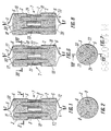
- the magnetic filter separator according to the invention contains two cylindrical chambers 2 and 3 which are arranged at a distance from one another and are connected to one another via a connecting piece 1 (FIG. 1), one of these chambers, namely the chamber 2, a connecting piece. 4 for supplying the fluid to be cleaned in the direction of arrow B and the other chamber 3 has a nozzle 5 for discharging the cleaned eluidum in the direction of arrow C.
- the connecting piece 1 is arranged along the longitudinal axis of the chambers 2 and 3 in the space between them.
- Each of the chambers 2 and 3 is filled with a ferromagnetic filling 6, whereby balls, alloyed shot, shredded chips, granulated ferrite and other granulated fillers, perforated plates and rods can be used as such.
- a ferromagnetic filling 6 whereby balls, alloyed shot, shredded chips, granulated ferrite and other granulated fillers, perforated plates and rods can be used as such.
- balls, alloyed shot, shredded chips, granulated ferrite and other granulated fillers, perforated plates and rods can be used as such.
- One skilled in the art can use other types of fillings depending on the type of fluid to be cleaned.
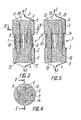
- a magnetic field acts on the ferromagnetic filling 6 from a magnetization system. 7 is generated which, as shown in FIGS. 1 and 2, has a pair of cores d and 9 arranged opposite one another and magnetic field sources 10 (FIG. 1).
- the end sections 11 and 12 of the cores 8 and 9 are accommodated in chambers 2 and 3 in the volume of the ferromagnetic filling 6 at a predetermined depth, which ensures the creation of the corresponding conditions for a uniform magnetization of the ferromagnetic filling 6 in each chamber 3 and 2.
- the remaining sections of the cores 8 and 9 are arranged on different sides of the nozzle between the chambers 2 and 3.
- the end sections 11 and 12 of the cores d and 9 of the same name with respect to magnetic poles are accommodated in the chambers 2 and 3 in the volume of the ferromagnetic filling 6 at different depths.
- the different depths of the accommodation of the end sections 11 and 12 of the cores 6 and 9 allow the density of the magnetic lines of force to be decentralized over the entire volume of the ferromagnetic filling 6, the required magnetization level to be generated over the entire volume of the filling 6 and the same conditions for to create the course of the process of magnetic separation of admixtures: this makes it possible to utilize the magnetomotive force of the magnetization system 7 appropriately.
- the fluid is cleaned to the required degree from the admixtures.
- Permanent magnets that are assembled into packages can of course be used as magnetic field sources.
- the embodiment variant of the magnetic filter separator shown in FIGS. 3, 4 and 5 is similar to the embodiment variant of the magnetic filter separator according to FIGS. 1 and 2.
- the magnetization system 7 (Fig. 3) has another pair of cores 13 (Figs. 4 and 5) and 14, the end portions 15 (Fig. 5) and 16 in the chambers 2 and 3 in the volume of ferromagnetic filling 6 similar to the end portions 11 (Fig. 3) and 12 housed the cores 8 and 9; are. ;
- Such an arrangement of the end sections 11, 12, 15 and 16 of the cores 8, 9, 13 and 14 allows different directivity of the averaged magnetic lines of force over the volume of the ferromagnetic filling 6, etc. to form a vortex-shaped, which leads to an equalization of the magnetization of the zones of the filling 6.
- the cores. 8, 9, 13 and 14 of the magnetization system 7 have the same length, which is intended to ensure the generation of the same magnetization force and the same conditions for the separation of the admixtures in the filling 6.
- cores of different lengths can be used to solve other technical tasks, e.g. in the cleaning of media which contain strong magnetic additives, where the requirements placed on the uniformity of the magnetization level of the filling are not so hard. There may also be other technical tasks that one skilled in the art will easily define.
- a magnetic filter separator which is shown in FIGS. 6, 7 and 8, can also be used for cleaning fluids.
- This embodiment variant of the filter separator is designed similarly to the filter separator shown in FIGS. 3, 4 and 5.
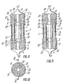
- FIGS. 9, 10 and 11 The embodiment variant of the magnetic filter separator shown in FIGS. 9, 10 and 11 is designed similarly to the magnetic filter separator according to FIGS. 6, 7 and 8.
- ferromagnetic bodies by 25 are provided to exclude the zones with reduced values of the induction of the magnetic field, which in the ferromagnetic filling 6 along the longitudinal axis of each of the Chambers 2 and 3 are arranged and have a means 26 for the passage of the fluid to be cleaned from one chamber 2 into the other chamber 3.
- the ferromagnetic bodies 25 are designed in the form of hollow cylinders. These bodies can also be designed as full cylinders.
- the means 26 for the passage of the clean the fluid from one chamber 2 into the other chamber 3 is in the form of a cup 27, the walls 28 of which have openings 29, the bottom 30 of the cup 27 being connected to the body 25 to exclude the zones with reduced values of the induction of the magnetic field , while the end faces of the walls 28 of the cup 27 are attached to the connecting piece 1.
- the variant of the magnetic filter separator shown in FIGS. 12, 13 and 14 is similar to the variant of the magnetic filter separator according to FIGS. 9, 10 and 11.
- the means 26 for the passage of the fluid to be cleaned from a chamber 2 into the chamber 3 in the form of nozzle 31, one end 32, with the chamber 2 in is in the immediate vicinity of the zone with an increased value of magnetic induction and the other end 33 is connected to the chamber 3 in the immediate vicinity of the zone with a reduced value of magnetic induction.
- the fluid to be cleaned passes successively through the zones with increased and decreased values of the magnetic induction of the chambers 2 and 3 and is cleaned of the additives to the required degree of cleaning.
- the end portions 34 (FIG. 12), 35, 36 (FIG. 14) and 37 of the cores 38 (FIG. 13), 39, 40 and 41 are in the form of sections 42 (FIGS. 12 and 14) according to the present invention. formed from metals with different magnetic permeability, which increases over the length of the end sections 34, 35, 36 and 37 of the cores 38, 39, 40 and 41 in the direction from the magnetic field sources 10.
- Metal with a magnetic permeability of 1000 to 50,000 can be used as the metal.
- the sections 42 of end sections 34, 35, 36 and 37 are conical, the cone tip pointing in the opposite direction to the arrangement of the magnetic field sources 10.
- the number of sections 42 can be two or more. This is determined by the height of the layer of the ferromagnetic filling 6.
- the sections can be multi-part, i.e. consist of several elements, or in one piece, z.ß. welded, trained.
- the embodiment variant of the magnetic filter separator shown in FIG. 15 is similar to the embodiment variant of the filter separator according to FIGS. 12, 13 and 14, but with the end sections 43 (FIG. 15) and 44 of the cores 45 and 46 in the chambers 3 and 2 in FIG Volume of the ferromagnetic filling 6 are housed at different depths, as shown in the filter separator according to FIGS. 3, 4 and 5.
- the end sections 43 and 44 of the cores 45 and 46 of the magnetization system 7 are provided with ferromagnetic scattering bodies 47 for scattering the magnetic flux, which are made of metals with different magnetic permeability, e.g. are made of metals with a magnetic permeability of 1000 to 50000.
- the scattering bodies 47 are variable Length trained. The length of each ferromagnetic scattering body 47 for scattering the magnetic flux in the direction from the magnetic field sources 10 exceeds the length of the preceding ferromagnetic scattering body 47.
- the ferromagnetic scattering bodies 47 are designed as conical rods.
- the ferromagnetic scattering bodies 47 which are made of metals with different magnetic permeability, increase the magnetization level of the filling 6, in particular in the region of the filling 6 that is distant from the magnetic field sources 10.
- Fig. 18 shows an alternative embodiment of the ferromagnetic diffuser 47 at the end portions 34 (35, 3 6 and 37) of the cores 38 (39, 40 and 41) of the magnetic Filterabscheiders shown in FIG. 12, mounted 13 and 14 and in the form of conical rods are formed, which have 48 projections 49 on their side surface.
- FIG. 19 shows an embodiment variant of the magnetic filter separator, which is similar to the magnetic filter separator according to FIGS. 12, 13 and 14 forms is.
- chambers 3 and 2 have a shape which corresponds to the shape of the end sections 34 and 35 of the cores 30 and 39 of the magnetization system 7.
- the ferromagnetic filling 6 in the chambers 2 and 3 ′ is separated from the connecting pieces 4 and 5 by a network 50. 1 to 19 the thickness of the walls is not necessarily indicated.
- the filter separator according to the invention has the following mode of operation.
- the fluid to be cleaned enters the chamber 2 in the direction of arrow B via the nozzle 4 (FIG. 1), flows through the ferromagnetic filling 6, which is magnetized by the magnetization system 7.
- the fluid which has been partially cleaned of the admixtures in the chamber 2 is fed via the nozzle 1 into the chamber 3, in which the fluid to be cleaned is cleaned.
- the fluid cleaned of the admixtures is discharged from the chamber 3 via the nozzle 5 in the direction of the arrow.
- the mode of operation of the magnetic filter separator according to the invention shown in FIGS. 3 to 19 is similar to the principle of operation of the magnetic filter separator according to FIGS. 1 and 2.
- the magnetization level of the filling 6 in the chambers 2 and 3 of the filter separator according to FIGS. 3, 4 and 5 and according to FIGS. 6, 7 and 8 is determined by using two pairs of cores 8, 9, 13 and 14 increased.
- the zones with reduced values of the induction of the magnetic field are excluded when cleaning the fluid by using the ferromagnetic bodies 25 of the filter separator according to FIGS. 9, 10 and 11.
- the predetermined magnetization level of the filling 6 when cleaning a fluid that contains weakly magnetic admixtures is achieved using the cores 38, 39, 40 and 41 and in the filter separator according to FIG. 15 using the ensures ferromagnetic scattering body 47.
- the number of zones with reduced values of the magnetic induction is reduced.
- the magnetic filter separator according to the invention allows the required degree of cleaning of a fluid - a liquid and a gaseous medium, which contains admixtures from products of corrosion with different degrees of dispersity from 0.01 to 10 ⁇ m and more, at a high speed of passage of the to ensure cleaning medium through the ferromagnetic filling, to achieve maximum use of the magnetic flux of the magnetization system to magnetize the entire volume of the ferromagnetic filling and to ensure a high degree of economy of the filter separator.
- the filter separator according to the invention also makes it possible to magnetize the layers of the filling up to the required level of magnetization both over the cross section and over the height of the layer of the filling, including the layers furthest away from the magnetic field sources, and to ensure the required degree of cleaning of the me diums both zones with reduced values of the induction of the magnetic field and zones with increased values of the induction.
- the magnetic filter separator according to the invention can be used in the chemical industry, in power engineering, in metallurgy, in mechanical engineering and in the biological industry for cleaning fluids and for cleaning natural water and waste water, for gas cleaning, preferably for rapid fine cleaning of the media Ferromagnetic and non-ferromagnetic admixtures, products of commissions, the products of wear on machine parts and the mechanical processing of parts are widely used.
Landscapes
- Plasma Technology (AREA)
- Water Treatment By Electricity Or Magnetism (AREA)
- Separation Using Semi-Permeable Membranes (AREA)
Abstract
Filtre-décanteur magnétique comprenant deux chambres d'interconnexion (2, 3), chacune remplie d'une charge ferromagnétique (6) soumise à l'effet du champ magnétique produit par un système de magnétisation (7). Les parties terminales (11, 12) des noyaux (8, 9) du système de magnétisation (7) sont placées dans les chambres (3, 2) et immergées dans la charge ferromagnétique (6) jusqu'à une certaine profondeur créant les conditions de magnétisation uniforme de la charge ferromagnétique (6) dans chaque chambre (3, 2).
Applications Claiming Priority (1)
| Application Number | Priority Date | Filing Date | Title |
|---|---|---|---|
| PCT/SU1987/000136 WO1989004710A1 (fr) | 1987-11-26 | 1987-11-26 | Filtre decanteur magnetique |
Publications (2)
| Publication Number | Publication Date |
|---|---|
| EP0406412A1 true EP0406412A1 (fr) | 1991-01-09 |
| EP0406412A4 EP0406412A4 (en) | 1991-04-10 |
Family
ID=21617153
Family Applications (1)
| Application Number | Title | Priority Date | Filing Date |
|---|---|---|---|
| EP19880902617 Withdrawn EP0406412A4 (en) | 1987-11-26 | 1987-11-26 | Magnetic filter-settler |
Country Status (5)
| Country | Link |
|---|---|
| EP (1) | EP0406412A4 (fr) |
| JP (1) | JPH02502349A (fr) |
| GB (1) | GB2223964A (fr) |
| IN (1) | IN169748B (fr) |
| WO (1) | WO1989004710A1 (fr) |
Families Citing this family (1)
| Publication number | Priority date | Publication date | Assignee | Title |
|---|---|---|---|---|
| RU2203124C1 (ru) * | 2002-01-31 | 2003-04-27 | Государственное предприятие Научно-исследовательский технологический институт им. А.П. Александрова | Высокоградиентный магнитный фильтр |
Family Cites Families (12)
| Publication number | Priority date | Publication date | Assignee | Title |
|---|---|---|---|---|
| DE1012871B (de) * | 1952-10-14 | 1957-08-01 | Faudi Feinbau G M B H | Elektromagnetisches Fluessigkeits-Topffilter |
| GB785418A (en) * | 1956-03-19 | 1957-10-30 | Philips Electrical Ind Ltd | Improvements in or relating to magnetic separators |
| CH521168A (de) * | 1970-07-22 | 1972-04-15 | Basf Ag | Vorrichtung zum Trennen und Entfernen ferromagnetischer Teilchen aus strömenden Medien |
| US3979288A (en) * | 1973-04-13 | 1976-09-07 | Kraftwerk Union Aktiengesellschaft | Double-flow magnetic filter, apparatus and method |
| SU472667A1 (ru) * | 1973-08-07 | 1975-06-05 | Харьковский Отдел Водного Хозяйства Промышленных Предприятий Всесоюзного Научно-Исследовательского Института Водоснабжения,Канализации,Гидротехнических Сооружений И Инженерной Гидрогеологии | Электромагнитный фильтр |
| DE2628095C3 (de) * | 1976-06-23 | 1981-08-06 | Siemens AG, 1000 Berlin und 8000 München | Magnetische Abscheidevorrichtung |
| US4170447A (en) * | 1977-01-11 | 1979-10-09 | Exxon Research & Engineering Co. | Method of separating solid particulate |
| US4244822A (en) * | 1979-08-09 | 1981-01-13 | The Babcock & Wilcox Company | Industrial technique magnetic apparatus |
| JPS5876115A (ja) * | 1981-11-02 | 1983-05-09 | Hitachi Ltd | 沸騰水型原子力発電プラントにおける冷却装置を備えた電磁フイルタ |
| JPS58119314A (ja) * | 1981-12-30 | 1983-07-15 | Daido Steel Co Ltd | 磁気分離方法及び磁気分離装置 |
| DE3304597C2 (de) * | 1983-02-10 | 1986-05-28 | Ukrainskij institut inženerov vodnogo chozjajstva, Rovno | Magnetseparator |
| DE3316443A1 (de) * | 1983-05-05 | 1984-11-08 | Ukrainskij institut inženerov vodnogo chozjajstva, Rovno | Abscheider zur magnetscheidung von feststoffteilchen aus fluessigen medien |
-
1987
- 1987-11-26 WO PCT/SU1987/000136 patent/WO1989004710A1/fr not_active Ceased
- 1987-11-26 JP JP63502343A patent/JPH02502349A/ja active Pending
- 1987-11-26 EP EP19880902617 patent/EP0406412A4/ru not_active Withdrawn
- 1987-12-28 IN IN1136/DEL/87A patent/IN169748B/en unknown
-
1988
- 1988-10-21 GB GB8824722A patent/GB2223964A/en not_active Withdrawn
Also Published As
| Publication number | Publication date |
|---|---|
| GB8824722D0 (en) | 1988-11-30 |
| EP0406412A4 (en) | 1991-04-10 |
| IN169748B (fr) | 1991-12-14 |
| WO1989004710A1 (fr) | 1989-06-01 |
| JPH02502349A (ja) | 1990-08-02 |
| GB2223964A (en) | 1990-04-25 |
Similar Documents
| Publication | Publication Date | Title |
|---|---|---|
| DE2551030C3 (de) | Abwasserreinigungsvorrichtung mit einer um eine liegende Welle rotierenden Vorrichtung mit Magneten | |
| DE2628095C3 (de) | Magnetische Abscheidevorrichtung | |
| DE3124276C2 (de) | Verfahren und Vorrichtung zur Trennung von Materialien unterschiedlicher Dichte mittels ferromagnetischer Flüssigkeit | |
| DE1241928B (de) | Magnetmechanisches Filter | |
| DE2659254A1 (de) | Verfahren und vorrichtung zum trennen von teilchen unterschiedlicher dichte mit magnetischen fluiden | |
| WO2010031679A1 (fr) | Dispositif de séparation destiné à éliminer des particules magnétisables et non magnétisables, transportées dans une suspension s’écoulant à travers un canal de séparation | |
| EP0742736A1 (fr) | Dispositif de separation d'emulsions huile dans l'eau par electrocoagulation | |
| DE3123229C2 (fr) | ||
| EP2199645A1 (fr) | Rainure de lubrification pour un engrenage et procédé de fabrication de la rainure de lubrification | |
| WO1997041587A1 (fr) | Installation a pulverisation cathodique a deux magnetrons longitudinaux | |
| DE3620660C2 (fr) | ||
| EP0242773A2 (fr) | Méthode pour la séparation continue de particules magnétisables et dispositif pour sa réalisation | |
| CH625728A5 (fr) | ||
| DE3532534C2 (de) | Trennapparat für Feststoffgemische | |
| DE60313635T2 (de) | Magnetische konditionierungsvorrichtung für dieselbrennstoff | |
| DE3316443C2 (fr) | ||
| DE2501858C2 (de) | Vorrichtung zum Abscheiden magnetisierbarer Teilchen, die in einer Flüssigkeit suspendiert sind | |
| DE112016005750T5 (de) | Magnetische matrix, starkfeldmagnetabscheider und verfahren zum einstellen des innerhalb solch einen abscheiders erzeugten magnetfeldes | |
| EP0292440B1 (fr) | Procédé de découpage par électroérosion | |
| DE69402262T2 (de) | Eingeschlossene Wirbelstrom Ultra-Mischvorrichtung | |
| DE10147842B4 (de) | Vorrichtung zur magnetisch geordneten Elektrodeionisation | |
| DE69220930T2 (de) | Magnetscheider | |
| DE1765948A1 (de) | Verfahren und Vorrichtung zum Entgraten von Werkstuecken | |
| DE2615581A1 (de) | Vorrichtung zum trennen magnetisierbarer teilchen von einem stroemungsfaehigen medium | |
| DE3304597A1 (de) | Magnetseparator |
Legal Events
| Date | Code | Title | Description |
|---|---|---|---|
| PUAI | Public reference made under article 153(3) epc to a published international application that has entered the european phase |
Free format text: ORIGINAL CODE: 0009012 |
|
| 17P | Request for examination filed |
Effective date: 19890712 |
|
| AK | Designated contracting states |
Kind code of ref document: A1 Designated state(s): DE FR IT SE |
|
| A4 | Supplementary search report drawn up and despatched |
Effective date: 19910218 |
|
| AK | Designated contracting states |
Kind code of ref document: A4 Designated state(s): DE FR IT SE |
|
| 17Q | First examination report despatched |
Effective date: 19910712 |
|
| STAA | Information on the status of an ep patent application or granted ep patent |
Free format text: STATUS: THE APPLICATION IS DEEMED TO BE WITHDRAWN |
|
| 18D | Application deemed to be withdrawn |
Effective date: 19920324 |