EP0407197A2 - Dispositif de sablage utilisant des particules pliantes - Google Patents
Dispositif de sablage utilisant des particules pliantes Download PDFInfo
- Publication number
- EP0407197A2 EP0407197A2 EP90307368A EP90307368A EP0407197A2 EP 0407197 A2 EP0407197 A2 EP 0407197A2 EP 90307368 A EP90307368 A EP 90307368A EP 90307368 A EP90307368 A EP 90307368A EP 0407197 A2 EP0407197 A2 EP 0407197A2
- Authority
- EP
- European Patent Office
- Prior art keywords
- media
- blasting
- blasting media
- storage container
- contaminants
- Prior art date
- Legal status (The legal status is an assumption and is not a legal conclusion. Google has not performed a legal analysis and makes no representation as to the accuracy of the status listed.)
- Granted
Links
Images


Classifications
-
- B—PERFORMING OPERATIONS; TRANSPORTING
- B24—GRINDING; POLISHING
- B24C—ABRASIVE OR RELATED BLASTING WITH PARTICULATE MATERIAL
- B24C7/00—Equipment for feeding abrasive material; Controlling the flowability, constitution, or other physical characteristics of abrasive blasts
- B24C7/0092—Equipment for feeding abrasive material; Controlling the flowability, constitution, or other physical characteristics of abrasive blasts the abrasive material being fed by mechanical means, e.g. by screw conveyors
-
- B—PERFORMING OPERATIONS; TRANSPORTING
- B24—GRINDING; POLISHING
- B24C—ABRASIVE OR RELATED BLASTING WITH PARTICULATE MATERIAL
- B24C11/00—Selection of abrasive materials or additives for abrasive blasts
-
- B—PERFORMING OPERATIONS; TRANSPORTING
- B24—GRINDING; POLISHING
- B24C—ABRASIVE OR RELATED BLASTING WITH PARTICULATE MATERIAL
- B24C11/00—Selection of abrasive materials or additives for abrasive blasts
- B24C11/005—Selection of abrasive materials or additives for abrasive blasts of additives, e.g. anti-corrosive or disinfecting agents in solid, liquid or gaseous form
-
- B—PERFORMING OPERATIONS; TRANSPORTING
- B24—GRINDING; POLISHING
- B24C—ABRASIVE OR RELATED BLASTING WITH PARTICULATE MATERIAL
- B24C9/00—Appurtenances of abrasive blasting machines or devices, e.g. working chambers, arrangements for handling used abrasive material
- B24C9/006—Treatment of used abrasive material
-
- Y—GENERAL TAGGING OF NEW TECHNOLOGICAL DEVELOPMENTS; GENERAL TAGGING OF CROSS-SECTIONAL TECHNOLOGIES SPANNING OVER SEVERAL SECTIONS OF THE IPC; TECHNICAL SUBJECTS COVERED BY FORMER USPC CROSS-REFERENCE ART COLLECTIONS [XRACs] AND DIGESTS
- Y02—TECHNOLOGIES OR APPLICATIONS FOR MITIGATION OR ADAPTATION AGAINST CLIMATE CHANGE
- Y02P—CLIMATE CHANGE MITIGATION TECHNOLOGIES IN THE PRODUCTION OR PROCESSING OF GOODS
- Y02P70/00—Climate change mitigation technologies in the production process for final industrial or consumer products
- Y02P70/10—Greenhouse gas [GHG] capture, material saving, heat recovery or other energy efficient measures, e.g. motor control, characterised by manufacturing processes, e.g. for rolling metal or metal working
Definitions
- the present invention relates to an improved blasting device for cleaning, degreasing and/or desooting a surface by using a pliant material of a desired porosity and size which is propelled by air pressure to impact against the surface and provide the necessary surface treatment.
- blasting devices are known in the prior art and such devices typically dispense materials which are relatively abrasive and heavy.
- U.S. Patent No. 2,426,072 issued to Ridgewood et al on August 19, 1947 relates to a method of projecting solid particles at high velocity against a surface to achieve the necessary cleaning.
- the disclosed projected particles are solid particles consisting of a synthetic resin having a desired impact strength and elongation and the contemplated materials are polymers.
- U.S. Patent No. 2,624,988 issued to Vander Wal on January 13, 1953 relates to a polishing and buffering liquid composition which is supplied at a pressure of approximately 200 pounds per square inch.
- the liquid composition is discharged, via flexible conduits, through nozzles and impinges on the article to be cleaned, and this can be seen in Figures 1 and 2.
- the liquid typically contains fragments of sponge rubber and fragments of felt, on the order of a quarter inch in diameter, which are used as a carrier for the abrasive material.
- U.S. Patent No. 2,652,662 issued to Newell on September 22, 1953 relates to an improved blasting apparatus which prevents bridging or jamming of the blasting grit material.
- This is achieved by employing agitating means such as a conduit having a plurality of downwardly directed holes, extending within and across the tank, for discharging a plurality of fluid streams into the hopper in order to assure that the blasting grit material is uniformly discharged and does not jam the hopper or opening.
- the air supplied to the agitating means helps to pressurize the tank.
- U.S. Patent No. 2,910,812 issued to Brunner on November 3, 1959 relates to a method of moistening black walnut shell grit so that it has greater impact and does not tend to accumulate a static charge which causes some of the grit particles to stick to the article being blasted.
- the reference teaches an arrangement in which water is sprayed from a nozzle, inside chamber, to moisten the black walnut shell grit to about a 10% moisture content.
- U.S. Patent No. 3,313,067 issued to Smith et al on 15 April 11, 1967 relates to a process for propelling discrete particles of polycarbonate resin having a mean diameter from about 25 mils to about 200 mils.
- the propelled particles have a velocity of between 50 and 300 feet per second and the particles are sprayed for a sufficient period of time to remove any "flashing" from the surface being treated.
- U.S. Patent No. 4,731,125 issued to Carr on March 15, 1988 relates to a surface cleaning method for removing paint and other coatings from composite surfaces formed of reinforced matrix material.
- the projected media has a Mohs scale hardness number lower than 3.5 and is accelerated by air at a pressure of approximately 40 pounds per square inch.
- This patent also indicates that the blasting process has the ability to selectively remove outer layers of material while leaving the underlying layers intact.
- a second object of the invention is to employ a light material which is essentially free from dust and less aggressive to most surfaces than the known prior art blasting media.
- a further object of the invention is to provide a supply container/mechanical feed arrangement which positively meters a desired quantity of the pliant blasting media into a pressurized air stream.
- a still further object of the invention is to provide a system which allows the pliant blasting media to be recovered, separated, cleaned, flushed and/or dried so that the blasting media can be reused.
- An additional object of the invention is to employ porous and/or non-porous blasting media which can be pre treated with liquids, powders, chemicals and/or solvents, before use, to enhance their action (cleaning, polishing, paint removing, etc.) of the surface.
- a further object of the invention is to employ blasting media which is much safer for the operator of the blasting device to use and much easier to contain because the blasting media only has a minimal tendency to ricochet off the surface being treated.
- Another object of the invention is to provide a media which is useful in treating (cleaning, degreasing and/or desooting) objects containing electrical wiring and other electronic components without damaging those electrical components.
- a still further object of the invention is to reduce the amount of contaminated liquid generated during the cleaning and/or degreasing operation because the media entraps and carries away the contaminants, and does not merely dilute the contaminants.
- porous blasting media means a light resilient material such as sponge, rubber, plastic or foam, including both open and closed cell, as well as other materials, such as hydrophilic sponge having a density of 50 lb/ft.3 or less.
- the present invention relates to blasting device, suitable for discharging pliant particulate media against a surface to achieve a desired surface treatment, said blasting device comprising a storage container, having an outlet, for containing a supply of pliant particulate blasting media; a discharge conduit having nozzle means connected to one end thereof; media feed means, connecting the outlet of said storage container to an end of the discharge conduit remote from said nozzle means, for supplying a desired quantity of blasting media from the storage container to the remote end of said discharge conduit; air supply means connected adjacent said discharge conduit, for supplying a flow of pressurized air thereto; and means for substantially preventing the back flow of pressurized air into said storage container; wherein said media feed means positively conveys said blasting media into said pressurized air flow in said discharge conduit to provide a continuous supply of blasting media to said nozzle means.
- the device comprises a hopper type storage container 8 which contains a supply of blasting media 23.
- the lower portion of the storage container 8 has a funnel-shaped portion 12 having an outlet 12′ in the bottom thereof.
- An conveyer device 15 connects the outlet 12′ of the storage container 8 with a discharge conduit or line 18 of preferably a 3/4" I.D. pipe.
- the conveyer device 15 comprises a housing having a cylindrical internal bore containing a screw conveyor mechanism 16, driven by motor 10 at a desired rate of speed.
- the screw conveyer mechanism and the housing have a desired tolerance which ensures positive feeding of the media.
- the housing has an inlet (not shown) connected with the outlet 12′ of the storage container and an outlet 17, remote from the housing inlet, connected with the discharge line 18.
- the conveyer device 15 positively and constantly meters the pliant blasting media 23 from the storage container to the discharge line.
- An air supply source 5 such as model no. 185 distributed by the Ingresoll Rand Company, has a first air supply line 6 connected to the top portion of storage container 8 and a second air supply line 7 connected adjacent the connection between the discharge line 18 and the conveyer device 15.
- the air supply source provides pressured air at least 20 psi, and preferably at about 90 psi.
- the entire blasting device from the air supply source 5 to discharge the nozzle 20, is pressurized.
- a non-return valve 85 (see Figure 2) could be positioned between the discharge line 18 and conveyer device 15 so that the conveyer device 15 and storage container 8 do not need to be pressurized.
- the blasting vessel 28 is a closed container having a bottom, four sidewalls and a removable cover 29.
- the blasting container 28 typically has a funnel shaped bottom portion 61 which assists in the collection and recovery of 15 the used blasting media 23′.
- a trap door 60 can be provided in the bottom of the vessel to facilitate removal of the used blasting media 23′.
- a supporting surface 24, such as a mesh screen or the like, is provided inside the vessel for supporting the objects 100 to be treated.
- the vessel is useful in batch processing in which the objects 100 are first placed inside the blasting vessel 28 on the support surface 24. Thereafter, the cover 29 is closed and secured in place and the pliant media blasting device 1 is activated.
- the media is then discharged from nozzle 20, positioned inside the blasting container 28, against the exterior surface of the objects 100 to be treated to accomplish the desired surface treatment. Once a sufficient amount of time has lapsed, the objects are checked and removed if they have been sufficiently treated. Thereafter, a second batch of objects can be treated or if the objects 100 were not sufficiently treated, they can be retreated.
- the storage container 8 is provided with agitation means such as vibrator device 22 located on the outside of the container, which shakes the container, or a rotatable agitator 21 (see Figure 2) provided inside the container, which continuously mixes the media.
- agitation means such as vibrator device 22 located on the outside of the container, which shakes the container, or a rotatable agitator 21 (see Figure 2) provided inside the container, which continuously mixes the media.
- FIG 2 this embodiment is similar to that shown in Figure 1 and like elements are represented by like numerals.
- the major difference between this embodiment and the embodiment of Figure 1 is the use of the agitator 21, located inside the storage container 8, and a motor 10 for rotating the same and the use of a flexible discharge line 18′, located adjacent the nozzle 20.
- the rotation of the agitator 21 helps prevent bridging and jamming of the blasting media, during use, while the flexible discharge line 18′ allows an operator of the blasting device 1 to precisely control the discharge direction, impingement angle, duration and other blasting parameters of the surface being treated.
- the device of Figure 2 can be used in a closed area, such as a small room or the like, if desired. However, since the pliant blasting media only minimally ricochets off the surface, recovery of the blasting media is relatively easy regardless of where it occurs.
- FIG. 3 shows a trough-type supply tank 13 which could be used instead of the supply container 8.
- Tank 13 is provided with screw conveyor 14 in the bottom portion thereof for conveying the blasting media to an outlet 11 of the tank.
- the outlet is connected to a discharge line 18 via a positive feed mechanism (not shown) such as the conveyer device 15.
- Figure 4 shows a device for separating used blasting media 23′ by its physical characteristics (shape, size, resiliency, etc.).
- the used blasting media 23′ is placed within a completely enclosed media supply container 48. Thereafter, air pressure is provided by air pressure source 5′, via inlet supply conduit or line 51, and this pressurized air carries a portion of the recovered blasting media 23′ contained in the container 48, through a discharge conduit or line 52, to a nozzle 54 which directs the blasting media against a deflection plate 55, typically made from metal.
- the debris and other undesired material 71 are typically not as resilient and thus they will not rebound as far from the deflection plate 55 and will fall and collect in a first container 57, located adjacent the deflection plate.
- Other separation devices such as a series of appropriately sized screens, could also be used to separate the blasting media from the debris.
- Figure 5 shows an alternate arrangement of the conveyer device 15 which is suitable for positively metering a constant amount of blasting media, in a vertical direction, from the supply container or tank into the discharge line 18.
- Such a feed mechanism could be used in combination with the trough-like supply tank of Figure 3, for instance.
- FIG. 6 shows a pliant media cleaning apparatus 30 used to remove absorbed liquids, chemicals and any remaining debris or undesired material from the separated blasting media 23 ⁇ .
- the cleaning apparatus 30 comprises a container having a bottom 39, a cylindrical sidewall 36 and a removable cover 32.
- the perforations in the wall are sized to allow the waste material to pass therethrough but retain the blasting media.
- the region formed between the sidewall 36 and the preformed wall 25 is in direct communication with a bleed air inlet 80 and an outlet 41 of the container, the outlet allows the liquids and debris squeezed from the blasting media to be exhausted from the apparatus.
- the center of the container is provided with a perforated pipe 38, shown in ghost lines, having an expandable bladder 35, made from a durable rubber or other strong but resilient material, tightly fastened to its exterior surface adjacent the top and bottom of the container.
- the bladder 35 is shown in its deflated position in Figure 6.
- the perforated pipe is supplied with pressurized air via supply conduit or line 47 and air pressure source 5 ⁇ to thereby inflate the bladder when desired.
- the blasting media is placed inside the apparatus 30 between the perforated wall 25 and the deflated expandable bladder 35.
- removable cover 32 is then positioned to seal the apparatus.
- air pressure is supplied to expandable bladder 35, via pressure line 47, and this air pressure inflates the expandable bladder 35 and thereby compresses the pliant blasting media against the perforated wall 25.
- the bladder 35 is further inflated and expanded it further compresses the blasting media against the perforated wall and thereby squeezes the absorbed liquids, chemicals and debris from the media.
- vacuum can be applied to the interior of apparatus 30, via a vacuum source 40, vacuum line 43, and outlet 41.
- the air inlet 80 allows only a small amount of air to enter into the apparatus so that a desired vacuum is maintained within the chamber. This vacuum assists with the compression the media and carries away the liquid and debris from the apparatus.
- the removed material is collected inside the recovery tank 45 of the vacuum source 40 where it thereafter can be appropriately disposed of, depending upon its composition. If the media is not adequately cleaned, it can be subjected to additional clean cycles.
- Other compression means such as a press and screen arrangement, can be used for removing absorbed liquids from the blasting media.
- the pressure applied to expandable bladder 35 will be between 20 and 60 psi, preferably 45 psi, and the partial vacuum applied to the apparatus will be between 20 and 22 inches of mercury. This combination of pressure and vacuum will ensure that the flushed blasting media, if unacceptable for reuse, can be safely disposed of in a land fill.
- other pressure and vacuum combinations will also work and are considered to be within the spirit and scope of the invention herein involved.
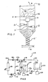
- FIG. 7 a third embodiment of the storage container is shown in which the conveyer device 15′ and the rotatable agitator 21′ are aligned vertically on the same axis and are both rotated by motor 10.
- the rotatable agitator 21′ can be provided with a series of paddles or other agitations members 21 ⁇ to agitate the media contained within the container and ensure the continuous supply of media to the conveyer device 15′.
- the top portion of the container is provided with two doors 90, 95 which are both arranged above the motor 10.
- the first door 90 can be pivoted open, in the direction of arrow B, to allow additional blasting media to be added to the top portion of the storage container, i.e. on top of door 95.
- the first door 90 is pivoted closed and the second door 95 can thereafter be slide in the direction of arrow A to open the door and allow the blasting media to fall into the storage container without interrupting operation of the device.
- both of the doors are provided with air-tight seals which enable them to withstand the applied pressures.
- the top portion of the storage container 8 is open to the atmosphere so that it may be continually supplied with virgin and/or recycled blasting media 23 during use.
- the lower portion of the container funnels into a cylindrical shaped elongate portion which is provided with a pair of vertically aligned, spaced apart butterfly valves or other similar valves 70, 72 that are operated by pneumatic, hydraulic or electrical means 74, 76, respectively.
- the valves chosen must be able to achieve an air tight seal, when in a closed position, which is able to withstand air pressures of about 100 psi, or even greater, and 3" butterfly valves manufactured by Watts Fluid Air of Portsmouth, New Hampshire have performed satisfactorily.
- the two valves 70, 72 operate independently of one another, i.e. one of the valves is always closed during operation, so as to maintain the pressurization of the blasting system.
- the butterfly valves 70, 72 and the conveyor device 15 divide the lower cylindrical portion of the storage container into two separate compartments 82, 84 which assist with batch feeding of the blasting media from the top portion of the storage container to the conveyor device 15.
- the first compartment 82 is defined between the conveyor device and the first butterfly valve 70 and the second compartment 84 is defined between the first butterfly valve 70 and the second butterfly valve 72.
- the device operates as follows. Prior to activating the device, both of the butterfly valves 70, 72 are moved to an opened position (shown in ghost in Figure 8) by the means 74, 76 and the blasting media 23 supplied to the top portion of the storage container is this allowed to fall by gravity into and fill the first and second compartments 82, 84. Thereafter, butterfly valves 70 and 72 are closed by the respective means 74, 76 so that an air tight seal is formed by each one of the rotatable butterfly valves 70, 72 for maintaining the air pressure of the system. Additional blasting media is then placed in the top portion of the storage container and the device is activated so that blasting of a desired surface can commence.
- the first butterfly valve 70 When additional media is required by the conveyor device 15, the first butterfly valve 70 is opened and this allows the blasting media 23 contained within second compartment 84 to fall, by gravity, into the first compartment 82.
- the opening of butterfly valve 70 also allows the pressurized air of the system to pressurize the second compartment 84.
- butterfly valve 70 is closed and butterfly valve 72 is then opened to allow the blasting media 23 contained within the top portion of the storage container to fall within the second compartment 84. It is to be noted that as second compartment 82 has been pressurized, upon opening of butterfly valve 72 an instantaneously release of the pressurized air occurs and it impacts again the blasting media 23 in the top portion of the storage container adjacent the butterfly valve 72.
- This air blast helps to loosen the blasting media and prevents bridging or jamming so that a continuous supply of blasting media is provided to the second compartment 84.
- the rotation of the butterfly valve 72 also assists with preventing bridging or jamming.
- the butterfly valve 72 is then closed until additional blasting media 23 is required. When this occurs, butterfly valve 70 is opened so that the blasting media contained in second compartment 84 can fall into the first compartment 82 and the above process is then repeated.
- the means 74 and 76 can be operated manually or can be controlled automatically when a sensor 86, such as a photo electronic sensor or the like, is provided in the cylindrical portion adjacent the convey means 15 to indicate when the first compartment 82 is about to run out of blasting media.
- the sensor 86 interacts with the control means 88 which sequentially activates means 74 or 76 to open automatically the valve 70 or 72 for a predetermined length of time so that automatic batch feed is achieved.
- a sight glass may be employed, instead to the sensor 86, to assist the operator with controlling the feed of the conveyor device.
- the cleaning apparatus comprises a washing container 104 into which the used blasting media 23 is placed. Water and/or some other cleaning fluid 11i is added to the container 104 to form a blasting media/liquid slurry 105. Additives such as soaps, degreasing agents and the like may be added to the cleaning fluid, if desired.
- a motor 106 is connected with agitating means 108, via a suitable water tight drive connection, to agitate the media/liquid slurry 105 and assist with removing and/or dissolving of the absorbed liquids and solids from the interstices of the blasting media.
- the slurry can be circulated by pump 112 which has an inlet connected with the base of the container 104 by conduit means 110 and has an outlet connected with the top portion of the container by return conduit means 114.
- the centrifuge 122 comprises a motor 124 which is connected to a rotatable drum 126 via a suitable water tight drive connection.
- a suitable centrifuge could be a modified washing machine, such as a machine manufactured by Sears, Roebuck & Co., and it is anticipated that other similar centrifuges will also provide satisfactory results.
- valve 128 of conduit means 130 is then opened and the liquid separated by the centrifuge is pumped by pump 112, via conduit means 130 and 110, to a filter 140.
- valve 134 of conduit means 114 must be closed and valves 138 and 142 of conduit means 136 must be opened.
- this pumped liquid has been sufficiently filtered and cleaned by the filter 140, it is then pumped back into the container 104, by closing valve 138 and opening valve 134, to be used for an additional cleaning cycle.
- the material 142 removed by filter 140 then can be appropriately treated, depending on its composition, and disposed of properly, e.g. in a land fill or the like.
- the cleaning apparatus can also be automatically controlled by computer mean so that the pump, the valves, the centrifuge and the filter are all timed to occur in a predetermined sequence. Such automation minimizes the operator attention and renders the system more efficient for use.
- the present invention allows both the blasting media and cleaning fluid to be used repeatedly and minimizes the amount of end product which has to be properly disposed of thereby resulting in a system which is very efficient to operate and has a minimal impact on the environment.
- a solvent, chemical or other cleansing agent can be added to the pliant blasting media in the cleaning apparatus and allowed to react for a time before the cleaning cycle commences.
- the addition of such additives help dissolve and/or remove harmful liquids or chemicals from the pliant blasting media.
- the pliant blasting media can be pretreated with a solvent, chemical, cleansing agent, liquid and/or powder, before the blasting media is used in the device 1, to enhance the media's surface treatment. Depending on the amount of liquid absorbed by the media, this will increase the density of the media and thereby increase its abrasiveness.
- An important feature of the pliant blasting media is its ability to entrap debris, liquids, solvents, etc., within its interstices and carry such materials away from the surface being treated.
Landscapes
- Engineering & Computer Science (AREA)
- Mechanical Engineering (AREA)
- Cleaning In General (AREA)
- Silicon Compounds (AREA)
- Dental Preparations (AREA)
- Electrochromic Elements, Electrophoresis, Or Variable Reflection Or Absorption Elements (AREA)
- Silver Salt Photography Or Processing Solution Therefor (AREA)
- Container, Conveyance, Adherence, Positioning, Of Wafer (AREA)
- Physical Or Chemical Processes And Apparatus (AREA)
Applications Claiming Priority (2)
| Application Number | Priority Date | Filing Date | Title |
|---|---|---|---|
| US37676489A | 1989-07-07 | 1989-07-07 | |
| US376764 | 2003-02-28 |
Publications (3)
| Publication Number | Publication Date |
|---|---|
| EP0407197A2 true EP0407197A2 (fr) | 1991-01-09 |
| EP0407197A3 EP0407197A3 (en) | 1992-04-01 |
| EP0407197B1 EP0407197B1 (fr) | 2001-10-04 |
Family
ID=23486389
Family Applications (1)
| Application Number | Title | Priority Date | Filing Date |
|---|---|---|---|
| EP90307368A Expired - Lifetime EP0407197B1 (fr) | 1989-07-07 | 1990-07-05 | Dispositif de sablage utilisant des particules pliantes |
Country Status (4)
| Country | Link |
|---|---|
| EP (1) | EP0407197B1 (fr) |
| AT (1) | ATE206344T1 (fr) |
| CA (1) | CA2020333C (fr) |
| DE (1) | DE69033815T2 (fr) |
Cited By (8)
| Publication number | Priority date | Publication date | Assignee | Title |
|---|---|---|---|---|
| FR2719788A1 (fr) * | 1994-05-13 | 1995-11-17 | Interblast | Installation de décapage. |
| WO1997017169A1 (fr) * | 1995-11-06 | 1997-05-15 | Heinrich Schlick Gmbh | Dispositif pour doser des materiaux granuleux coulants, notamment des grenailles |
| EP0798081A3 (fr) * | 1996-03-26 | 1998-05-20 | Kamei Tekkosho Ltd. | Procédé et dispositif au jet abrasif pour meuler une pièce d'usinage |
| EP0890417A1 (fr) * | 1997-07-10 | 1999-01-13 | Tokyo Ohka Kogyo Co., Ltd. | Abrasif de plastique pour sablage, procédé de traitement de sablage d'un substat de visualisation par panneau à plasma utilisant le même abrasif et procédé pour le traitememt de déchets de sablage |
| EP1897657B1 (fr) * | 2006-09-07 | 2011-06-15 | Whirlwind Utilities Ltd. | Appareil de sablage à vis doseuse dans le courant de gaz véhicule |
| CN112847155A (zh) * | 2021-03-29 | 2021-05-28 | 河南五建建设集团有限公司 | 一种建筑小工件简易喷砂处理装置 |
| CN112917373A (zh) * | 2021-03-29 | 2021-06-08 | 河南五建建设集团有限公司 | 一种建筑小构件除锈装置 |
| CN117161986A (zh) * | 2023-09-20 | 2023-12-05 | 中国科学院金属研究所 | 一种构件复杂内部结构表面处理的工具 |
Families Citing this family (2)
| Publication number | Priority date | Publication date | Assignee | Title |
|---|---|---|---|---|
| DE102009048879A1 (de) * | 2009-10-09 | 2011-04-21 | Mvv O & M Gmbh | Verfahren und Vorrichtung zur Reinigung von rauchgasbeaufschlagten Heizflächen eines Wärmetauschers in einer Verbrennungsanlage während des Betriebs derselben |
| CN109434699A (zh) * | 2018-10-31 | 2019-03-08 | 湖南中路华程桥梁科技股份有限公司 | 一种可除杂的抛丸机丸料循环料仓 |
Family Cites Families (13)
| Publication number | Priority date | Publication date | Assignee | Title |
|---|---|---|---|---|
| DE225021C (fr) * | ||||
| GB218911A (en) * | 1923-09-19 | 1924-07-17 | Benjamin Rush Peacock | Improvements in flexible coupling discs for transmission purposes |
| DE1266219B (de) * | 1964-05-19 | 1968-04-11 | Willy Bleuler Dipl Ing | Schleuse, die bei pneumatischen Foerdereinrichtungen als Aufgabe- oder Entnahmeeinrichtung dient |
| DE2048524A1 (en) * | 1970-08-25 | 1972-04-13 | Heinz Hoelter | Pneumatic plastics - conveyor - with dosing device and gas tight double charging valve |
| DE2220225A1 (de) * | 1972-04-25 | 1973-11-08 | Goldmann Kg Friedr | Drucksandstrahlgeblaese |
| DE3131002A1 (de) * | 1981-08-05 | 1983-03-24 | Sergiu Dipl.-Ing. 8000 München Caftanat | Automatische druckstrahlanlage mit genauer und reproduzierbarer dosierung des strahlmittels und kontinuierlichem betrieb |
| CH654510A5 (en) * | 1982-03-04 | 1986-02-28 | Werner Hunziker | Abrasive-blasting machine |
| US4439073A (en) * | 1982-04-30 | 1984-03-27 | White Harold J | Filling hole swing valve for sandblasters |
| GB2128911B (en) * | 1982-10-22 | 1986-04-16 | Shiftworker Limited | Sand blasting apparatus |
| US4731125A (en) * | 1984-04-19 | 1988-03-15 | Carr Lawrence S | Media blast paint removal system |
| EP0218869A1 (fr) * | 1985-09-20 | 1987-04-22 | SCHLICK-Roto-Jet Maschinenbau GmbH | Dispositif pour le dosage uniforme d'un matériau abrasif en forme de grenailles pour dispositifs de traitement pneumatique au jet abrasif |
| NL8801397A (nl) * | 1987-11-16 | 1989-06-16 | Walter Posthumus | Gritstraalinrichting. |
| CH674096A5 (fr) * | 1988-01-19 | 1990-04-30 | Lonza Ag |
-
1990
- 1990-07-03 CA CA002020333A patent/CA2020333C/fr not_active Expired - Fee Related
- 1990-07-05 EP EP90307368A patent/EP0407197B1/fr not_active Expired - Lifetime
- 1990-07-05 DE DE69033815T patent/DE69033815T2/de not_active Expired - Fee Related
- 1990-07-05 AT AT90307368T patent/ATE206344T1/de not_active IP Right Cessation
Cited By (13)
| Publication number | Priority date | Publication date | Assignee | Title |
|---|---|---|---|---|
| FR2719788A1 (fr) * | 1994-05-13 | 1995-11-17 | Interblast | Installation de décapage. |
| US6000995A (en) * | 1995-11-06 | 1999-12-14 | Heinrich Schlick | Unit for the dosage of grained, pourable materials, in particular blasting abrasives |
| WO1997017169A1 (fr) * | 1995-11-06 | 1997-05-15 | Heinrich Schlick Gmbh | Dispositif pour doser des materiaux granuleux coulants, notamment des grenailles |
| EP0798081A3 (fr) * | 1996-03-26 | 1998-05-20 | Kamei Tekkosho Ltd. | Procédé et dispositif au jet abrasif pour meuler une pièce d'usinage |
| US6368195B1 (en) * | 1997-07-10 | 2002-04-09 | Tokyo Ohka Kogyo Co., Ltd. | Plastic abrasive for sandblasting, method for sandblast processing plasma display panel substrate using the same and method for treating sandblasting waste matters |
| US6126513A (en) * | 1997-07-10 | 2000-10-03 | Tokyo Ohka Kogyo Co., Ltd. | Plastic abrasive for sandblasting, method for sandblast processing plasma display panel substrate using the same and method for treating sandblasting waste matters |
| EP0890417A1 (fr) * | 1997-07-10 | 1999-01-13 | Tokyo Ohka Kogyo Co., Ltd. | Abrasif de plastique pour sablage, procédé de traitement de sablage d'un substat de visualisation par panneau à plasma utilisant le même abrasif et procédé pour le traitememt de déchets de sablage |
| US6641628B1 (en) | 1997-07-10 | 2003-11-04 | Tokyo Ohka Kogyo Co., Ltd. | Plastic abrasive for sandblasting, method for sandblast processing plasma display panel substrate using the same and method for treating sandblasting waste matters |
| EP1897657B1 (fr) * | 2006-09-07 | 2011-06-15 | Whirlwind Utilities Ltd. | Appareil de sablage à vis doseuse dans le courant de gaz véhicule |
| AU2007293306B2 (en) * | 2006-09-07 | 2015-04-09 | Nu Flow Technologies 2020 Inc. | Pipe Cleaning Apparatus |
| CN112847155A (zh) * | 2021-03-29 | 2021-05-28 | 河南五建建设集团有限公司 | 一种建筑小工件简易喷砂处理装置 |
| CN112917373A (zh) * | 2021-03-29 | 2021-06-08 | 河南五建建设集团有限公司 | 一种建筑小构件除锈装置 |
| CN117161986A (zh) * | 2023-09-20 | 2023-12-05 | 中国科学院金属研究所 | 一种构件复杂内部结构表面处理的工具 |
Also Published As
| Publication number | Publication date |
|---|---|
| EP0407197A3 (en) | 1992-04-01 |
| CA2020333A1 (fr) | 1991-01-08 |
| EP0407197B1 (fr) | 2001-10-04 |
| CA2020333C (fr) | 2001-05-29 |
| DE69033815T2 (de) | 2002-06-13 |
| ATE206344T1 (de) | 2001-10-15 |
| DE69033815D1 (de) | 2001-11-08 |
Similar Documents
| Publication | Publication Date | Title |
|---|---|---|
| US5325638A (en) | Pliant media blasting device | |
| US5207034A (en) | Pliant media blasting device | |
| US5146716A (en) | Pliant media blasting method | |
| EP0407197B1 (fr) | Dispositif de sablage utilisant des particules pliantes | |
| CA2322304C (fr) | Appareil et methode de recyclage de boue liquide excavee | |
| US5524769A (en) | Counterflow aggregate recovery apparatus | |
| JPH0735021B2 (ja) | ブラスト媒体の回収及び浄化システム | |
| JP2009517196A (ja) | ダスト処理機構 | |
| US4771579A (en) | Abrasive blast media recovery and cleaning for reuse | |
| CN113042172A (zh) | 煤矸石固废转化建材智能系统 | |
| JP3013053B2 (ja) | ブラスト装置 | |
| JP3499402B2 (ja) | アスファルト廃材から骨材を再生する方法 | |
| JP3149237B2 (ja) | ろ過材のリサイクル装置 | |
| EP0805735B1 (fr) | Procede de regeneration de la grenaille, utile dans un dispositif sous pression | |
| WO2020067536A1 (fr) | Dispositif d'usinage par jet et procédé d'usinage par jet | |
| JP3057548B2 (ja) | 予熱被塗物の自動循環式粉体塗装装置 | |
| JP2814228B2 (ja) | ブラストクリーニング用研装材供給装置 | |
| JPH01288385A (ja) | 管の清掃方法及び装置 | |
| JP7136451B2 (ja) | 有害廃棄物の回収方法、再利用材の回収方法及び有害廃棄物回収システム | |
| DE19535474C1 (de) | Vorrichtung zum Austragen eines aus chemisch reaktiven Kunststoffkomponenten gebildeten Kunststoffgemisches | |
| JPH04258367A (ja) | 粉粒体の清浄方法及び装置 | |
| GB2313072A (en) | Separation of wet building mortar and concrete | |
| US10155178B2 (en) | Waste liquid solidification system and method | |
| CN224142465U (zh) | 一种钢铁杂质分离精细筛选装置 | |
| CN112645398A (zh) | 废液固化系统及方法 |
Legal Events
| Date | Code | Title | Description |
|---|---|---|---|
| PUAI | Public reference made under article 153(3) epc to a published international application that has entered the european phase |
Free format text: ORIGINAL CODE: 0009012 |
|
| AK | Designated contracting states |
Kind code of ref document: A2 Designated state(s): AT BE CH DE DK ES FR GB GR IT LI LU NL SE |
|
| PUAL | Search report despatched |
Free format text: ORIGINAL CODE: 0009013 |
|
| AK | Designated contracting states |
Kind code of ref document: A3 Designated state(s): AT BE CH DE DK ES FR GB GR IT LI LU NL SE |
|
| 17P | Request for examination filed |
Effective date: 19920918 |
|
| 17Q | First examination report despatched |
Effective date: 19930908 |
|
| RAP1 | Party data changed (applicant data changed or rights of an application transferred) |
Owner name: SPONGE-JET, INC. |
|
| RIN1 | Information on inventor provided before grant (corrected) |
Inventor name: LYNN, WILLIAM R. |
|
| APAB | Appeal dossier modified |
Free format text: ORIGINAL CODE: EPIDOS NOAPE |
|
| APAB | Appeal dossier modified |
Free format text: ORIGINAL CODE: EPIDOS NOAPE |
|
| APAD | Appeal reference recorded |
Free format text: ORIGINAL CODE: EPIDOS REFNE |
|
| APAD | Appeal reference recorded |
Free format text: ORIGINAL CODE: EPIDOS REFNE |
|
| APCB | Communication from the board of appeal sent |
Free format text: ORIGINAL CODE: EPIDOS OBAPE |
|
| APCB | Communication from the board of appeal sent |
Free format text: ORIGINAL CODE: EPIDOS OBAPE |
|
| APCB | Communication from the board of appeal sent |
Free format text: ORIGINAL CODE: EPIDOS OBAPE |
|
| APAB | Appeal dossier modified |
Free format text: ORIGINAL CODE: EPIDOS NOAPE |
|
| GRAG | Despatch of communication of intention to grant |
Free format text: ORIGINAL CODE: EPIDOS AGRA |
|
| GRAH | Despatch of communication of intention to grant a patent |
Free format text: ORIGINAL CODE: EPIDOS IGRA |
|
| GRAH | Despatch of communication of intention to grant a patent |
Free format text: ORIGINAL CODE: EPIDOS IGRA |
|
| GRAA | (expected) grant |
Free format text: ORIGINAL CODE: 0009210 |
|
| AK | Designated contracting states |
Kind code of ref document: B1 Designated state(s): AT BE CH DE DK ES FR GB GR IT LI LU NL SE |
|
| REF | Corresponds to: |
Ref document number: 206344 Country of ref document: AT Date of ref document: 20011015 Kind code of ref document: T |
|
| REG | Reference to a national code |
Ref country code: CH Ref legal event code: EP |
|
| REF | Corresponds to: |
Ref document number: 69033815 Country of ref document: DE Date of ref document: 20011108 |
|
| REG | Reference to a national code |
Ref country code: CH Ref legal event code: NV Representative=s name: ISLER & PEDRAZZINI AG |
|
| RAP2 | Party data changed (patent owner data changed or rights of a patent transferred) |
Owner name: SPONGE-JET, INC. |
|
| ET | Fr: translation filed | ||
| REG | Reference to a national code |
Ref country code: GB Ref legal event code: IF02 |
|
| PG25 | Lapsed in a contracting state [announced via postgrant information from national office to epo] |
Ref country code: DK Free format text: LAPSE BECAUSE OF FAILURE TO SUBMIT A TRANSLATION OF THE DESCRIPTION OR TO PAY THE FEE WITHIN THE PRESCRIBED TIME-LIMIT Effective date: 20020104 Ref country code: SE Free format text: LAPSE BECAUSE OF FAILURE TO SUBMIT A TRANSLATION OF THE DESCRIPTION OR TO PAY THE FEE WITHIN THE PRESCRIBED TIME-LIMIT Effective date: 20020104 |
|
| PG25 | Lapsed in a contracting state [announced via postgrant information from national office to epo] |
Ref country code: GR Free format text: LAPSE BECAUSE OF FAILURE TO SUBMIT A TRANSLATION OF THE DESCRIPTION OR TO PAY THE FEE WITHIN THE PRESCRIBED TIME-LIMIT Effective date: 20020105 |
|
| NLT2 | Nl: modifications (of names), taken from the european patent patent bulletin |
Owner name: SPONGE-JET, INC. |
|
| PG25 | Lapsed in a contracting state [announced via postgrant information from national office to epo] |
Ref country code: ES Free format text: LAPSE BECAUSE OF FAILURE TO SUBMIT A TRANSLATION OF THE DESCRIPTION OR TO PAY THE FEE WITHIN THE PRESCRIBED TIME-LIMIT Effective date: 20020430 |
|
| PG25 | Lapsed in a contracting state [announced via postgrant information from national office to epo] |
Ref country code: LU Free format text: LAPSE BECAUSE OF NON-PAYMENT OF DUE FEES Effective date: 20020705 |
|
| PLBE | No opposition filed within time limit |
Free format text: ORIGINAL CODE: 0009261 |
|
| STAA | Information on the status of an ep patent application or granted ep patent |
Free format text: STATUS: NO OPPOSITION FILED WITHIN TIME LIMIT |
|
| 26N | No opposition filed | ||
| REG | Reference to a national code |
Ref country code: FR Ref legal event code: CA |
|
| PGFP | Annual fee paid to national office [announced via postgrant information from national office to epo] |
Ref country code: CH Payment date: 20030715 Year of fee payment: 14 |
|
| PGFP | Annual fee paid to national office [announced via postgrant information from national office to epo] |
Ref country code: AT Payment date: 20030731 Year of fee payment: 14 |
|
| PG25 | Lapsed in a contracting state [announced via postgrant information from national office to epo] |
Ref country code: AT Free format text: LAPSE BECAUSE OF NON-PAYMENT OF DUE FEES Effective date: 20040705 |
|
| PG25 | Lapsed in a contracting state [announced via postgrant information from national office to epo] |
Ref country code: LI Free format text: LAPSE BECAUSE OF NON-PAYMENT OF DUE FEES Effective date: 20040731 Ref country code: CH Free format text: LAPSE BECAUSE OF NON-PAYMENT OF DUE FEES Effective date: 20040731 |
|
| REG | Reference to a national code |
Ref country code: CH Ref legal event code: PL |
|
| PG25 | Lapsed in a contracting state [announced via postgrant information from national office to epo] |
Ref country code: IT Free format text: LAPSE BECAUSE OF NON-PAYMENT OF DUE FEES Effective date: 20050705 |
|
| PGFP | Annual fee paid to national office [announced via postgrant information from national office to epo] |
Ref country code: NL Payment date: 20050713 Year of fee payment: 16 |
|
| PGFP | Annual fee paid to national office [announced via postgrant information from national office to epo] |
Ref country code: DE Payment date: 20050715 Year of fee payment: 16 |
|
| PGFP | Annual fee paid to national office [announced via postgrant information from national office to epo] |
Ref country code: BE Payment date: 20050802 Year of fee payment: 16 |
|
| APAH | Appeal reference modified |
Free format text: ORIGINAL CODE: EPIDOSCREFNO |
|
| PG25 | Lapsed in a contracting state [announced via postgrant information from national office to epo] |
Ref country code: BE Free format text: LAPSE BECAUSE OF NON-PAYMENT OF DUE FEES Effective date: 20060731 |
|
| PG25 | Lapsed in a contracting state [announced via postgrant information from national office to epo] |
Ref country code: DE Free format text: LAPSE BECAUSE OF NON-PAYMENT OF DUE FEES Effective date: 20070201 Ref country code: NL Free format text: LAPSE BECAUSE OF NON-PAYMENT OF DUE FEES Effective date: 20070201 |
|
| NLV4 | Nl: lapsed or anulled due to non-payment of the annual fee |
Effective date: 20070201 |
|
| BERE | Be: lapsed |
Owner name: *SPONGE-JET INC. Effective date: 20060731 |
|
| PGFP | Annual fee paid to national office [announced via postgrant information from national office to epo] |
Ref country code: FR Payment date: 20080714 Year of fee payment: 19 |
|
| PGFP | Annual fee paid to national office [announced via postgrant information from national office to epo] |
Ref country code: GB Payment date: 20080702 Year of fee payment: 19 |
|
| GBPC | Gb: european patent ceased through non-payment of renewal fee |
Effective date: 20090705 |
|
| REG | Reference to a national code |
Ref country code: FR Ref legal event code: ST Effective date: 20100331 |
|
| PG25 | Lapsed in a contracting state [announced via postgrant information from national office to epo] |
Ref country code: FR Free format text: LAPSE BECAUSE OF NON-PAYMENT OF DUE FEES Effective date: 20090731 |
|
| PG25 | Lapsed in a contracting state [announced via postgrant information from national office to epo] |
Ref country code: GB Free format text: LAPSE BECAUSE OF NON-PAYMENT OF DUE FEES Effective date: 20090705 |