EP0407208A2 - Appareil pour manipuler et imprimer du papier à deux couches plié en accordéon - Google Patents
Appareil pour manipuler et imprimer du papier à deux couches plié en accordéon Download PDFInfo
- Publication number
- EP0407208A2 EP0407208A2 EP90307389A EP90307389A EP0407208A2 EP 0407208 A2 EP0407208 A2 EP 0407208A2 EP 90307389 A EP90307389 A EP 90307389A EP 90307389 A EP90307389 A EP 90307389A EP 0407208 A2 EP0407208 A2 EP 0407208A2
- Authority
- EP
- European Patent Office
- Prior art keywords
- ply
- paper
- plies
- printing
- separator
- Prior art date
- Legal status (The legal status is an assumption and is not a legal conclusion. Google has not performed a legal analysis and makes no representation as to the accuracy of the status listed.)
- Withdrawn
Links
Images




Classifications
-
- B—PERFORMING OPERATIONS; TRANSPORTING
- B41—PRINTING; LINING MACHINES; TYPEWRITERS; STAMPS
- B41J—TYPEWRITERS; SELECTIVE PRINTING MECHANISMS, i.e. MECHANISMS PRINTING OTHERWISE THAN FROM A FORME; CORRECTION OF TYPOGRAPHICAL ERRORS
- B41J15/00—Devices or arrangements of selective printing mechanisms, e.g. ink-jet printers or thermal printers, specially adapted for supporting or handling copy material in continuous form, e.g. webs
- B41J15/18—Multiple web-feeding apparatus
- B41J15/20—Multiple web-feeding apparatus for webs superimposed during printing
Definitions
- the present invention generally relates to printing and paper handling, and more particularly to apparatus for printing and handling multiple-ply fanfold paper in which the plies are separated.
- Prior art printing and handling methods for multiple-ply fanfold paper involve printing in one machine and subsequently separating the plies in another machine, and do not recognize that the two processes can be combined in the same machine to increase efficiency and lower costs.
- a printing and handling apparatus for printing and handling multiple-ply continuous paper comprising at least a first ply and a second ply, including print means for printing on said paper, and feeding means for feeding said paper past said print means, characterized by first separation means for separating said first and second plies prior to being printed on, merging means for bringing said first and second plies together at said print means, and second separator means for separating said first and second plies after being printed on.
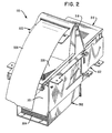
- Figures 1 and 2 show front and rear isometric views of a printing and handling apparatus 100. Handling of paper by the apparatus 100 involves separating the plies of multiple-ply fanfold paper and (continuously) neatly refolding and stacking one of the plies in a tray after printing has occurred.
- the reference numbers in Figures 1 and 2 pertain to components which will be described later while referring to Figures 3 and 9.
- the side view of the printing and handling apparatus 100 in Figure 3 is more illustrative of the process.
- the major components of the apparatus 100 are a lower tray 302, a separator bar (or ply separator) 310, a printer 312 (described more fully with reference to Figure 8), a deflection cover 318 an upper tray 318, and a paper guide 322,
- the fanfold paper 301 which is self-reprographic (eg carbon-less) and has two plies in the preferred embodiment, is introduced to the apparatus 100 in a supply stack 304 of the lower tray 302.
- the paper 301 is separated into two plies 306 and 308 by wedging a portion of the separator bar 310 therebetween, prior to the paper being printed upon. Although the plies are separated, the positioning of the plies relative to each other does not change.
- the separated plies 306 and 308 are merged in a channel 314 for printing by the printer 312.
- the printer 312 simultaneously prints and advances the plies 306 and 308 through the channel 314, the result being the production of two identical plies.
- the deflector cover 316 deflects the printed plies towards the upper tray 318, upon which the deflector cover 316 is mounted. In addition to being mounted upon the upper tray 318, the deflector cover 316 is also attached to the paper guide 322. A path 320 between the upper tray 318 and the paper guide 322 allows the second ply 308 to be deflected and neatly refolded and stacked into a stack 328. The first ply 306 advances over the top of the paper guide 322 to exit the printing and handling apparatus 100.
- the first ply 306 can either be viewed through a window 904 (seen best in Figures 1, 9 and 13) in the deflector cover 316 or by looking at that ply on the top of the paper guide and from the rear of the apparatus 100 (the view seen in Figure 2, for example), etc. After the user has verified and checked the information on the first ply 306, he may, for example, discard that ply and simply retain the neatly refolded second ply 308 (stacked in stack 328) in the upper tray 318.
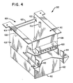
- FIG. 4 shows a more detailed version of the lower tray 302 (front view).
- the lower tray 302 has an end wall 402, an open space area 404 approximately equal in area to the end wall 402, two side walls 406 and 408, a bottom surface 410, and an upper open space area 412 approximately equal in area to the area of the bottom surface 410.
- Two printer locators 414 and 416 locate and secure the printer 312 when the apparatus 100 is fully assembled.
- Two upper tray locator tabs 418 and 420 locate the correct positioning of the upper tray 318 when the apparatus is fully assembled.
- Two separator bar holes 422 and 424 serve both as separator bar 310 locators and as anchors for said bar.
- a horizontal bar member 426 serves as a convenient handle for grasping the lower tray 302, when it is assembled in the apparatus 100, for example. Also, a ledge 428 which impinges upon the paper as it leaves the lower tray 302 serves to align the paper with the channel 314.
- FIG. 5 The rear view of the lower tray 302 in Figure 5 contains the same elements as in Figure 4, except that Figure 5 additionally shows separator bar locators 502 and 504.
- the separator bar locators 502 and 504 are for locating and supporting the separator bar 310.
- the separator bar 310 is detailed in Figure 6.
- the separator bar 310 contain a paper separator portion 602, two end bar portions 604 and 606, and two end posts 608 and 610 for positioning in the separator bar holes 422 and 424.
- Figure 7 shows the lower tray 302 with the separator bar 310 in place (stems 608 and 610 resting in holes 422 and 424, respectively, and the elbows 612 and 614 of the separator bar 310 resting upon the separator bar locators 502 and 504).
- FIG. 8 illustrates the printer 312, which is described in more detail in US-A-4,204,777.
- the printer 312 has a printer mechanism 802 for printing onto the fanfold paper, and a feeder mechanism (or feeder) designated generally as 804, for advancing the paper past the printer mechanism 802.
- the printer mechanism 802 may be of the dot matrix pin variety, daisy wheel variety, or other variety, as will be appreciated by those skilled in the art.
- the deflector cover 316 in Figure 9 has a base or frame 902, the open area 904, and a group of hooks 906-914.
- the rear view of the deflector cover 316 in Figure 10 additionally reveals a paper separation slot 1002 through which the first ply 306 of the paper 301 exits the deflector cover 316, two snap hooks 1004 and 1006 and two locator tabs 1008 and 1010 for attaching the deflector cover 316 to the upper tray 318.
- the upper tray 318 in Figure 11 has a sloped surface 1102 with deflector cover holes 1104 and 1106 which receive snap hooks 1004 and 1006, respectively, and holes 1108 and 1110 which receive the locator tabs 1008 and 1010, respectively.
- the base 1112 includes a resting bar 1114 upon which the paper guide 322 rests, and a hollow 1116 which permits easy grasping of the stack 328 for removal.
- Two notches 1118 (seen in Figure 13) and 1120 fit over the upper tray locator tabs 418 and 420 (see Figure 4) to correctly position the upper tray 318 with respect to the lower tray 302 when the apparatus 100 is fully assembled.
- the paper guide 322 in Figure 12 has two slightly angled surfaces 1202 and 1204 which merge into a relatively flat planar surface portion 1206 with cutouts 1208-1216.
- the cutouts 1208-1216 accept the hooks 906-914 of the deflector cover 316 to attach the paper guide 322 to the deflector cover 316, such as is shown in Figures 13 (front view of upper tray, deflector cover and paper guide) and 14 (rear view of upper tray, deflector cover and paper guide).
- the first ply 306 is fed through the opening 1002 over the top of the paper guide 322, while the second ply 308 continues on the path 320 under the paper guide 322 and is deflected thereby to cause the paper second ply to refold and stack neatly underneath the paper guide 322.
- the printed paper can be made either to travel over the top of the apparatus 100, or underneath the paper guide 322 to form a neatly refolded stack. The same applies to two-ply fanfold paper where it is not desired to separate the plies.
- the fanfold paper need not be limited to having two plies. In the case where more than two plies are separated, the number of separator bars is equal to n-1, where n represents the number of plies.
- the other components can be appropriately modified.
Landscapes
- Sheets, Magazines, And Separation Thereof (AREA)
- Handling Of Continuous Sheets Of Paper (AREA)
- Pile Receivers (AREA)
Applications Claiming Priority (2)
| Application Number | Priority Date | Filing Date | Title |
|---|---|---|---|
| US37678789A | 1989-07-07 | 1989-07-07 | |
| US376787 | 1989-07-07 |
Publications (2)
| Publication Number | Publication Date |
|---|---|
| EP0407208A2 true EP0407208A2 (fr) | 1991-01-09 |
| EP0407208A3 EP0407208A3 (en) | 1992-10-21 |
Family
ID=23486491
Family Applications (1)
| Application Number | Title | Priority Date | Filing Date |
|---|---|---|---|
| EP19900307389 Withdrawn EP0407208A3 (en) | 1989-07-07 | 1990-07-06 | Apparatus for handling and printing two-ply fanfold paper |
Country Status (3)
| Country | Link |
|---|---|
| EP (1) | EP0407208A3 (fr) |
| JP (1) | JPH0345370A (fr) |
| CA (1) | CA2016861A1 (fr) |
Cited By (2)
| Publication number | Priority date | Publication date | Assignee | Title |
|---|---|---|---|---|
| FR2680340A1 (fr) * | 1991-08-14 | 1993-02-19 | Axiohm | Dispositif d'impression simultanee sur au moins deux bandes de papier. |
| FR2681816A1 (fr) * | 1991-09-30 | 1993-04-02 | Axiohm | Perfectionnement aux dispositifs d'impression simultanee sur au moins deux bandes de papier. |
Family Cites Families (2)
| Publication number | Priority date | Publication date | Assignee | Title |
|---|---|---|---|---|
| GB972439A (en) * | 1962-09-28 | 1964-10-14 | Lamson Paragon Ltd | Improvements in or relating to transfer material feeding means |
| GB1132839A (en) * | 1965-12-15 | 1968-11-06 | Lamson Paragon Ltd | Apparatus for feeding paper |
-
1990
- 1990-05-15 CA CA 2016861 patent/CA2016861A1/fr not_active Abandoned
- 1990-07-06 JP JP17766290A patent/JPH0345370A/ja active Pending
- 1990-07-06 EP EP19900307389 patent/EP0407208A3/en not_active Withdrawn
Cited By (2)
| Publication number | Priority date | Publication date | Assignee | Title |
|---|---|---|---|---|
| FR2680340A1 (fr) * | 1991-08-14 | 1993-02-19 | Axiohm | Dispositif d'impression simultanee sur au moins deux bandes de papier. |
| FR2681816A1 (fr) * | 1991-09-30 | 1993-04-02 | Axiohm | Perfectionnement aux dispositifs d'impression simultanee sur au moins deux bandes de papier. |
Also Published As
| Publication number | Publication date |
|---|---|
| EP0407208A3 (en) | 1992-10-21 |
| JPH0345370A (ja) | 1991-02-26 |
| CA2016861A1 (fr) | 1991-01-07 |
Similar Documents
| Publication | Publication Date | Title |
|---|---|---|
| EP0045640B1 (fr) | Dispositif de convoyage de feuilles | |
| US4900001A (en) | Apparatus for printing on both sides of continuous webs in a format producing collated stacks of ordered pages | |
| EP0227344B1 (fr) | Imprimante à mécanisme d'alimentation en support d'impression amovible | |
| JPS62215428A (ja) | 選択式給紙装置 | |
| US5820281A (en) | Printer with discrete sheet load enhancement apparatus and method | |
| EP0407208A2 (fr) | Appareil pour manipuler et imprimer du papier à deux couches plié en accordéon | |
| US5066151A (en) | Device comprising a printing mechanism | |
| US5806842A (en) | Output paper sheet finishing module and method of using same | |
| US4408916A (en) | Feed-in device for continuous forms for a printer | |
| US5599120A (en) | Adapter for ink jet printing onto adhesive binding tape | |
| US5069435A (en) | Sheet stacker having sheet-feed function | |
| US4717273A (en) | Multiple paper holder and method for a computer printer | |
| US5184906A (en) | Adjustable envelope cassette | |
| US5054758A (en) | Multi-ply paper separator | |
| JPH02286546A (ja) | 給排紙トレイ | |
| JPH06316124A (ja) | プリンタ装置 | |
| JPH11192764A (ja) | 印字位置調整機能を備えたプリンタ装置 | |
| US5581977A (en) | Method for handling and printing paperboard trays in a packaging machine | |
| EP0416489A2 (fr) | Machine à assembler avec imprimante | |
| US20040017464A1 (en) | Sorter for ink-jet printer | |
| JP2653917B2 (ja) | 給紙機能付スタッカ | |
| JPH1053368A (ja) | 画像形成装置 | |
| EP0550033A3 (fr) | Dispositif de sélection de panier de papier dans une imprimante | |
| JPH04313521A (ja) | 用紙カートリッジ | |
| JP2903535B2 (ja) | プリンタ |
Legal Events
| Date | Code | Title | Description |
|---|---|---|---|
| PUAI | Public reference made under article 153(3) epc to a published international application that has entered the european phase |
Free format text: ORIGINAL CODE: 0009012 |
|
| AK | Designated contracting states |
Kind code of ref document: A2 Designated state(s): DE FR GB |
|
| PUAL | Search report despatched |
Free format text: ORIGINAL CODE: 0009013 |
|
| AK | Designated contracting states |
Kind code of ref document: A3 Designated state(s): DE FR GB |
|
| 17P | Request for examination filed |
Effective date: 19930407 |
|
| 17Q | First examination report despatched |
Effective date: 19930607 |
|
| STAA | Information on the status of an ep patent application or granted ep patent |
Free format text: STATUS: THE APPLICATION IS DEEMED TO BE WITHDRAWN |
|
| 18D | Application deemed to be withdrawn |
Effective date: 19931018 |