EP0407321A1 - Mähconditioner mit Mitteln zum Ändern des von den Schneidorganen erzeugten Luftstroms - Google Patents
Mähconditioner mit Mitteln zum Ändern des von den Schneidorganen erzeugten Luftstroms Download PDFInfo
- Publication number
- EP0407321A1 EP0407321A1 EP90440061A EP90440061A EP0407321A1 EP 0407321 A1 EP0407321 A1 EP 0407321A1 EP 90440061 A EP90440061 A EP 90440061A EP 90440061 A EP90440061 A EP 90440061A EP 0407321 A1 EP0407321 A1 EP 0407321A1
- Authority
- EP
- European Patent Office
- Prior art keywords
- mower
- conditioner according
- air flow
- cutting
- work
- Prior art date
- Legal status (The legal status is an assumption and is not a legal conclusion. Google has not performed a legal analysis and makes no representation as to the accuracy of the status listed.)
- Granted
Links
- 230000003750 conditioning effect Effects 0.000 claims abstract description 25
- 230000004048 modification Effects 0.000 claims description 62
- 238000012986 modification Methods 0.000 claims description 62
- 239000000463 material Substances 0.000 claims description 11
- 241001484259 Lacuna Species 0.000 abstract 1
- 230000004907 flux Effects 0.000 description 4
- 210000000056 organ Anatomy 0.000 description 2
- 230000006978 adaptation Effects 0.000 description 1
- 230000000295 complement effect Effects 0.000 description 1
- 238000006073 displacement reaction Methods 0.000 description 1
- 238000001035 drying Methods 0.000 description 1
- 238000002347 injection Methods 0.000 description 1
- 239000007924 injection Substances 0.000 description 1
- 239000003607 modifier Substances 0.000 description 1
- 238000004806 packaging method and process Methods 0.000 description 1
- 239000004033 plastic Substances 0.000 description 1
Images




Classifications
-
- A—HUMAN NECESSITIES
- A01—AGRICULTURE; FORESTRY; ANIMAL HUSBANDRY; HUNTING; TRAPPING; FISHING
- A01D—HARVESTING; MOWING
- A01D43/00—Mowers combined with apparatus performing additional operations while mowing
- A01D43/10—Mowers combined with apparatus performing additional operations while mowing with means for crushing or bruising the mown crop
-
- A—HUMAN NECESSITIES
- A01—AGRICULTURE; FORESTRY; ANIMAL HUSBANDRY; HUNTING; TRAPPING; FISHING
- A01D—HARVESTING; MOWING
- A01D34/00—Mowers; Mowing apparatus of harvesters
- A01D34/01—Mowers; Mowing apparatus of harvesters characterised by features relating to the type of cutting apparatus
- A01D34/412—Mowers; Mowing apparatus of harvesters characterised by features relating to the type of cutting apparatus having rotating cutters
- A01D34/63—Mowers; Mowing apparatus of harvesters characterised by features relating to the type of cutting apparatus having rotating cutters having cutters rotating about a vertical axis
- A01D34/64—Mowers; Mowing apparatus of harvesters characterised by features relating to the type of cutting apparatus having rotating cutters having cutters rotating about a vertical axis mounted on a vehicle, e.g. a tractor, or drawn by an animal or a vehicle
- A01D34/66—Mowers; Mowing apparatus of harvesters characterised by features relating to the type of cutting apparatus having rotating cutters having cutters rotating about a vertical axis mounted on a vehicle, e.g. a tractor, or drawn by an animal or a vehicle with two or more cutters
- A01D34/667—Means for directing the cut crop
Definitions
- the present invention relates to a mower-conditioner comprising at least one mowing group provided with cutting members arranged above a casing in a row transverse to the direction of advance to work and each comprising at least one cutting tool , said cutting members rotating each about a corresponding axis directed upwards, and a conditioning group associated with said mowing group, in particular of the type comprising two conditioning rollers also extending transversely to the direction of advance at working and turning each around its longitudinal axis in order to pass between them the product cut by the cutting members.
- Such mower-conditioners are used for mowing a product to be harvested, then mechanically treating the cut product in order to speed up its drying. This mechanical treatment is carried out by the two conditioning rollers which extend behind the cutting area of the cutting members and between which the product cut by said cutting members passes.
- the product cut by the cutting members is forced to pass between the two conditioning rollers by the simultaneous action of projection carried out by the rotary cutting members and of entanglement carried out by the conditioning rollers.
- the cutting members must have, at their upper part in particular, a certain shape capable of generating this action of projection of the cut product towards the zone of entanglement of the packaging rollers. If this shape greatly favors the projection of the cut product towards the conditioning rollers, it also generates a significant displacement of air.
- the object of the present invention is to remedy this drawback.
- the present invention provides that at least in the area where the cutting tool or tools of an intermediate cutting member move, taking into account the direction of advance during work, forwards during rotation. of said cutting member, extends a member for modifying the air flow generated by said cutting member.
- this air flow modification member is arranged so that its lower end extends in the vicinity of said corresponding cutting member (s) and, when viewed from above, at least substantially at the inside of the extreme trajectory (ies) described by the said cutting tool (s) of the corresponding cutting member (s).
- the air flow modification member forms a screen for the air flows directed towards the front and stops or deflects these, so that the residual air flow directed towards the front is almost zero, or even zero. It has indeed been found, under the conditions mentioned above, that with such an organ for modifying the air flow, even the product which is a few centimeters in front of said organ, remained almost, even perfectly straight.
- the lower end of the air flow modification member is provided to extend, when viewed from above, at least substantially inside the extreme trajectory or paths described by the cutting tools of the corresponding cutting member or members, it is ensured that said member for modifying the air flow does not itself bend the product to be cut.
- the working part of the air flow modification member has at the rear, taking into account the direction of advance to work, a deflecting face extending transversely to lead ahead to work and headed up.
- this deflecting face is curved and preferably concave. Thanks to this last characteristic, the air flow is divided into two and each half-flow is directed laterally outwards and more or less rearwards.
- the division of the air flow and the guidance of the two half-flows can be further improved if the deflecting face has a rib directed upwards and the apex of which is directed towards the rear, so that said deflecting face has two surfaces adjacent concaves.
- this front face is curved and preferably convex. Thanks to this last characteristic, the product cut by the cutting member or members associated with said air flow modification member passes well on either side of said air flow modification member.
- a particularly simple embodiment of such a member for modifying the air flow is obtained when the working part thereof consists of a thin wall.
- This wall may be rigid or deformable. In the latter case, it will advantageously be made of a flexible material, preferably rubber.
- the thin wall forming the working part of the air flow modification member is made of a flexible material, it is also particularly advantageous for it to be curved so that its deflecting face, that is to say say the one next to the conditioning group, or concave.
- said thin wall can be easily deformed towards the rear to be erased in the event of encountering an obstacle, but on the other hand has excellent rigidity towards the front, so that the air flow that it must deflect, do not deform it forward.
- the lower end of the working part of the air flow modification member has a shape which follows at least substantially the upper outer contour of the volume generated by the corresponding cutting member or members during their rotation.
- the air flow modification member thus forms a total screen for the air flow generated by the corresponding said cutting member (s).
- the lower end of the air flow modification member is straight and extends at least substantially horizontally.
- a member for modifying the air flow associated with two neighboring cutting members whose directions of rotation diverge forward that at least the working part has a width at most equal to the distance separating the two axes of rotation of these two cutting members.
- At least the lower end of the working part of a member for modifying the air flow extends in the vicinity of the line joining the two axes of rotation of the two corresponding cutting members or in front of this line.
- a connecting device connects the air flow modification member in a removable manner to the mower-conditioner. This allows in particular to disassemble said air flow modification member under conditions where its use is unnecessary or to replace it when it is damaged or worn.
- this connecting device to include adjustment means allowing the position, in particular of the working part of the air flow modification member to be adjusted at least substantially in the direction of advance at work and / or at least substantially in a height direction. This characteristic allows an optimal adaptation of the air flow modification member to the different conditions encountered.
- the air flow modification member comprises a deformable connecting part.
- This characteristic is particularly advantageous when the working part is relatively rigid. It allows said working part to be erased in the event of an obstacle being encountered.
- a particularly simple embodiment of such a deformable connecting part will be obtained when it is provided in flexible material.
- this flexible material will be rubber.
- connection part of the air flow modification member prefferably has a thin wall shape.
- the thin wall forming the connecting part of the air flow modification member is made of a flexible material, it is also particularly advantageous for it to be curved so that its concave face is directed towards the back.
- said connecting part can be easily deformed towards the rear to allow the working part, which may be, in this case, relatively rigid, to be erased in the event of encountering an obstacle, but on the other hand has excellent forward rigidity, so that the air flow cannot move said working part forward.
- a particularly advantageous embodiment of such a member for modifying the air flow is obtained when the latter is constituted by a single piece forming both the working part and the connecting part.
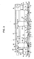
- the mower-conditioner shown in FIGS. 1 to 3 comprises a mowing group (1) provided in a nonlimiting manner with five cutting members (2, 3, 4, 5, 6).
- the cutting members (2, 3, 4, 5, 6) are guided in rotation to the upper face of a casing (7) and rotate each around an axis (8) directed upwards.
- the cutting members (2 and 4) rotate in the direction defined by the arrow (9), while the cutting members (3, 5 and 6) rotate in the opposite direction defined by the arrow (10).
- the cutting members (2, 3, 4, 5, 6) are arranged in a row extending at least substantially perpendicular to the direction of advance (A) at work.
- Each cutting member (2, 3, 4, 5, 6) is constituted by a support for cutting tools (11, 12) and by cutting tools (13).
- the end cutters (2, 6), unlike the intermediate cutters (3, 4, 5), are additionally each provided with a rotating drum (14, 15) which surmounts the support corresponding cutting tools (11).
- a gearbox (16) intended to transmit the movement to the cutting members (2, 3, 4, 5, 6).
- a carrying beam (17) which extends a certain distance above the cutting members (2, 3, 4 , 5, 6) at least substantially in the plane containing the axes of rotation (8) of said cutting members (2, 3, 4, 5, 6) and at least substantially parallel to the casing (7).
- This support beam (17) is linked at one of its ends to the gearbox (16).
- This conditioning group (21) comprises two conditioning rollers (22, 23) which extend substantially one above the other and at least substantially perpendicular to the direction of advance (A) at work. These conditioning rollers (22, 23) rotate around their respective longitudinal axes and in opposite directions according to the arrows (24, 25) defined in FIG. 2, so that the product cut by the cutting members (2, 3, 4, 5, 6) passes between said conditioning rollers (22, 23) to undergo the desired treatment.
- These conditioning rollers (22, 23) are each guided in rotation in bearings (26) arranged on side walls (27). These side walls (27) extend at least substantially vertically and at least substantially along the advance direction (A) at work.
- the two side walls (27) are linked together by a cover (28) at least substantially horizontal.
- This cover (28) and the two side walls (27) thus form a conditioning channel (29) which is part of the conditioning group (21) and in which the two conditioning rollers (22, 23) extend.
- the cutting members (2, 4) rotate, as said above, in the direction of rotation (9), while the cutting members (3, 5 and 6) rotate in the opposite direction of rotation ( 10).
- the right end cutting member (2) and the first intermediate cutting member (3) form a pair of counter-rotating cutting members (2; 3), the respective directions of rotation (9; 10) of which converge at the front of the housing (7).
- the second intermediate cutting member (4) and the third intermediate cutting member (5) also form a pair of counter-rotating cutting members (4; 5), the respective directions of rotation (9; 10) of which converge. also at the front of the housing (7).
- the left end cutter (6) rotates in the direction of rotation (10), opposite to the direction of rotation (9) of the right end cutter (2), by so as to bring the product which it has cut, inside the conditioning channel (29).
- the product cut by each pair of counter-rotating cutting members (2, 3; 4, 5) is thus substantially concentrated in the middle part (30: 31) between the two cutting members (2, 3; 4, 5) of said pair, then is projected backwards into the catchment area (32) (FIG. 2) of the two conditioning rollers (22, 23).
- At least part of the product cut by the left end cutter (6) is concentrated in the zone (33) located on the side of the drum (15) facing the adjacent intermediate cutter (5), then is also projected by said end cutting member (6) backwards into the catchment area (32) of the two conditioning rollers (22, 23).
- first intermediate cutting member (3) and the second intermediate cutting member (4) form a pair of counter-rotating cutting members (3; 4), the directions of which respective rotation (10; 9) diverge at the front of the casing (7).
- the cutting tools (13) of these intermediate cutting members (3, 4 ) move during the rotational movement, towards the front edge (35) of the housing (7).
- the cutting members (2, 3; 4, 5) evacuate the product they have cut by passing it through the middle part (30; 31) extending between them. In doing so, each pair of cutting members (2, 3; 4, 5) also displaces a certain mass of air. Since it is practically unable to exit from the rear, given that the conditioning rollers (22, 23) form, as is very precisely shown in FIG. 3, a veritable screen, these air masses are then concentrated in the area ( 34), respectively in the area (36) and re-driven forward by the intermediate cutting members (3, 4), respectively by the intermediate cutting member (5).
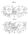
- the air flow modification member (37) which is associated with the intermediate cutting members (3, 4) extends, in view in the direction of advance (A) at work, at least substantially symmetrically between the two corresponding intermediate cutters (3, 4) ( Figure 4).
- This air flow modification member (37) comprises a working part (39), intended to extend into the air flow generated by the intermediate cutting members (3, 4) in the area (34), and a connecting part (40) via which said air flow modification member (37) is linked to the support beam (17).
- the air flow modification member (37) consists of a single thin wall (41) made of a flexible material, in this case rubber. This single thin wall (41) constitutes both the working part (39) and the connecting part (40).
- the latter comprises a support (42) having a convex front face (43) having, in order to above, a substantially cylindrical surface portion shape.
- the connecting part (40) of the air flow modification member (37) is brought into contact with this front face (43) of the support (42) and is fixed there by means of screws (44) screwed into threaded holes (not shown) made in said support (42).
- the air flow modification member (37) is thus fixed to the support beam (17) and extends downwards in the direction of the corresponding intermediate cutting members (3, 4).
- connection part (40) of the air flow modification member (37) is brought into contact with the front face (43) of the support (42). Therefore, it adopts the shape of said front face (43), that is to say that when viewed from above, it has a curved shape, the concavity of which is directed towards the rear, taking account of the direction early (A) at work.
- the working part (39) also takes a similar shape ( Figure 4), so that it then has at the rear, taking into account the direction of advance (A) at work, a deflecting face (45) concave and a convex front face (46).
- this deflecting face (45) and this front face (46) extend transversely to the direction of advance (A) at work and are directed upwards, in this case at least substantially vertically.
- FIG. 4 shows very precisely in FIG. 4, that the working part (39), in particular the lower end (47) thereof (FIG.
- the lower end (47) of the air flow modification member (37) extends in the vicinity of the upper face of the cutting tool supports (12) of the cutting members (3, 4) correspondents.
- This lower end (47) is, in view along the direction of advance (A) at work, at least substantially straight and extends at least substantially horizontally and transversely to said direction of advance (A) at work.
- the air flow modification member (38) which is associated with the intermediate cutting member (5) is similar to the air flow modification member (37).
- This air flow modification member (38) has a working part (53) intended to extend into the air flow generated by the intermediate cutting member (5). in the area (36) and a connecting part (54) through which said air flow modification member (38) is linked to the support beam (17).
- This air flow modification member (38) also consists of a single thin wall (55) made of a flexible material, in this case rubber. This single thin wall (55) constitutes both the working part (53) and the connecting part (54).
- the latter comprises a support (56) having a convex front face (57) having, in order to above, a substantially cylindrical surface portion shape.
- the connecting part (54) of the air flow modification member (38) is brought into contact with this front face (57) of the support (56) and is fixed there by means of screws (58) screwed into threaded holes (not shown) made in said support (56).
- the air flow modification member (38) is thus fixed to the support beam (17) and extends downwards in the direction of the corresponding intermediate cutting member (5).
- the connecting part (54) of the air flow modification member (38) is brought into contact with the front face (57) of the support (56). Therefore, it adopts the shape of said front face (57), that is to say that when viewed from above, it has a curved shape, the concavity of which is directed towards the rear, taking account of the direction in advance (A) at work.
- the working part (53) also takes a similar shape, so that it then has at the rear, taking account of the direction of advance (A) at work, a deflecting face (59) concave and a front face (60 ) convex. This deflecting face (59) and this front face (60) extend transversely to the direction of advance (A) at work and are directed upwards.
- the working part (53), in particular the lower end (61) thereof extends, in top view closer to the point front intersection (62) of the extreme trajectories (63, 64) described by the cutting tools (13) of the cutting members (5, 6), that the working part (39) of the member for modifying the flow d 'air (37).
- this working part (53) does not extend symmetrically between the intermediate cutting member (5) and the end cutting member (6), but is, on the contrary, somewhat offset towards the intermediate cutting member (5).
- the width of the working part (53), in particular of the lower end (61) thereof is approximately equal to half the distance separating the two axes of rotation (8) of the two members cutting (5, 6).
- the lower end (61) of the air flow modification member (38) extends in the vicinity of the upper face of the cutting tool supports (12, 11) of the cutting members (5, 6).
- This lower end (61) has, in view along the direction of advance (A) at work, a shape which at least substantially follows the upper external contour of the volume generated by the cutting members (5, 6) during their rotation .
- the air flow modification member (65), shown in Figures 6 to 8, is made of plastic and its shape is obtained by injection. It comprises a working part (66) and a connecting part (67) by means of which it is linked to the carrying beam (17). This is, for this purpose, provided with a support (68) having a front face (69) having the shape complementary to the concave rear face (70) of the connecting part (67) with which it is intended to be in touch.
- the connection of the air flow modification member (65) to the support (68) is made by means of two screws (71) screwed into threaded holes (not shown) made in the support (68).
- the deflecting face (73) of the working part (66) of said air flow modification member (65) has a rib (74) directed upwards and the top (75) of which is directed rearward, taking account of the direction of advance (A) at work.
- the deflecting face (73) thus has two adjacent concave surfaces (76, 77). Thanks to this shape, the air flow is divided into two half-flows by the rib (74) which are each deflected laterally and rearward by the respective concave surfaces (76, 77).
- connection part (67) stops at the connection part (67) so that the latter retains the shape of a thin curved wall to allow the working part (66) to clear back when it hits an obstacle.
- the air flow modification member (78), shown in FIGS. 9 and 10, differs from the preceding air flow modification members (37, 38, 65) in that the working part (79) and the connecting part (80) are formed by two separate parts.
- the connecting part (80) is constituted by a thin flat wall made of a flexible material, in this case rubber.
- the working part (79) meanwhile, consists of a curved thin wall made of a rigid material. It has a concave deflecting face (81) directed towards the rear and a convex front face (82) directed towards the front. In its upper part, the working part (79) has an approximately flat shape so that it can be linked to the lower part of the connecting part (80) by means of rivets (83) for example.
- the connecting part (80) is linked to the supporting beam (84) by means of a connecting device (85) comprising a bracket (86) which has a horizontal wing (87) in contact with the lower face (88) of the support beam (84) having a square section, and a vertical wing (89) extending at a certain distance in front of the front face (90) of the support beam (84).
- a connecting device (85) comprising a bracket (86) which has a horizontal wing (87) in contact with the lower face (88) of the support beam (84) having a square section, and a vertical wing (89) extending at a certain distance in front of the front face (90) of the support beam (84).
- FIG. 10 it appears that the lateral edges (91, 92) of the vertical wing (89) are folded forward, so that when viewed from above, the vertical wing (89) has a shape of U in which the connecting part (80) rests.
- the support beam (84), for its part, is provided with a guide (93) against which is applied one of the lateral edges of the horizontal wing (87).
- the bracket (86) is linked to the support beam (84) by means of a screw (96) which passes through the oblong hole (94) produced in the horizontal wing (87) and which is screwed into a threaded hole ( 97) produced in the lower face (88) of the support beam (84).
- the connecting part (80) for its part, is linked to the vertical wing (89) by means of a bolt (98) which passes through a through hole (99) produced in said connecting part (80) thus that the oblong hole (95) made in the vertical wing (89).
- the air flow modification members (37, 38, 65, 78) which have just been described, are moreover arranged in such a way that, when their working part (39, 53, 66, 79) disappears in case of meeting with an obstacle, it cannot be caught by the conditioning rollers (22, 23).
- the air flow modification members (37, 38, 65) could be perfectly linked to the support beam (17) by means of a connecting device allowing the position of said members to be adjusted relative to the corresponding cutting members (3, 4, 5).
- the lower end (100) of the air flow modification member (65) and the lower end (101) of the air flow modification member (78) may have, in view in the direction of advance (A) at work, a shape similar to the lower end (47) of the air flow modification member (37) or to the lower end (61) of the air flow modification member (38).
Landscapes
- Life Sciences & Earth Sciences (AREA)
- Environmental Sciences (AREA)
- Harvester Elements (AREA)
Applications Claiming Priority (2)
| Application Number | Priority Date | Filing Date | Title |
|---|---|---|---|
| FR8909364 | 1989-07-07 | ||
| FR8909364A FR2649283B1 (fr) | 1989-07-07 | 1989-07-07 | Faucheuse-conditionneuse munie d'organes de modification du flux d'air engendre par les organes de coupe |
Publications (2)
| Publication Number | Publication Date |
|---|---|
| EP0407321A1 true EP0407321A1 (de) | 1991-01-09 |
| EP0407321B1 EP0407321B1 (de) | 1993-11-03 |
Family
ID=9383706
Family Applications (1)
| Application Number | Title | Priority Date | Filing Date |
|---|---|---|---|
| EP19900440061 Expired - Lifetime EP0407321B1 (de) | 1989-07-07 | 1990-07-05 | Mähconditioner mit Mitteln zum Ändern des von den Schneidorganen erzeugten Luftstroms |
Country Status (4)
| Country | Link |
|---|---|
| EP (1) | EP0407321B1 (de) |
| DE (1) | DE69004359T2 (de) |
| DK (1) | DK0407321T3 (de) |
| FR (1) | FR2649283B1 (de) |
Cited By (5)
| Publication number | Priority date | Publication date | Assignee | Title |
|---|---|---|---|---|
| EP0541470A1 (de) * | 1991-11-08 | 1993-05-12 | Kuhn S.A. | Mähmaschine mit einem Rotor, welcher das geschnittene Gut insbesondere zu den Trägern der Schneidorgane bringt |
| NL9400824A (nl) * | 1994-05-19 | 1996-01-02 | Maasland Nv | Maaimachine. |
| FR2763474A1 (fr) * | 1997-05-26 | 1998-11-27 | Kuhn Sa | Coiffe d'andainage pour faucheuse a elements de coupe rotatifs |
| EP0772386A4 (de) * | 1994-04-28 | 2000-08-16 | Hay & Forage Ind | Fördermittel für aussenliegende messer eines mähwerkes |
| EP0772387A4 (de) * | 1994-04-28 | 2000-08-16 | Hay & Forage Ind | Breitschnitterntemaschine mit rotierender schneidevorrichtung |
Citations (6)
| Publication number | Priority date | Publication date | Assignee | Title |
|---|---|---|---|---|
| DE1582375B1 (de) * | 1967-12-29 | 1970-05-14 | Fahr Ag Maschf | Kreiselmaeher |
| DE1582342A1 (de) * | 1967-08-12 | 1970-07-30 | Friedrich Moertl | Rotierende Werkzeuge an Rotations-Maehwerken |
| EP0099314A2 (de) * | 1982-07-09 | 1984-01-25 | Kuhn S.A. | Vorrichtung zum Verhindern von Erdanhäufung am Gehäuse eines Scheibenmähers |
| DE3419358A1 (de) * | 1983-06-27 | 1985-01-10 | Deere & Co., Moline, Ill., US, Niederlassung Deere & Co. European Office, 6800 Mannheim | Maehwerksvorrichtung |
| DE8811183U1 (de) * | 1988-09-05 | 1988-10-20 | H. Niemeyer Söhne GmbH & Co KG, 4446 Hörstel | Mähmaschine |
| EP0297011A1 (de) * | 1987-06-26 | 1988-12-28 | Kuhn S.A. | Mähconditioner |
-
1989
- 1989-07-07 FR FR8909364A patent/FR2649283B1/fr not_active Expired - Fee Related
-
1990
- 1990-07-05 EP EP19900440061 patent/EP0407321B1/de not_active Expired - Lifetime
- 1990-07-05 DE DE1990604359 patent/DE69004359T2/de not_active Expired - Fee Related
- 1990-07-05 DK DK90440061T patent/DK0407321T3/da active
Patent Citations (6)
| Publication number | Priority date | Publication date | Assignee | Title |
|---|---|---|---|---|
| DE1582342A1 (de) * | 1967-08-12 | 1970-07-30 | Friedrich Moertl | Rotierende Werkzeuge an Rotations-Maehwerken |
| DE1582375B1 (de) * | 1967-12-29 | 1970-05-14 | Fahr Ag Maschf | Kreiselmaeher |
| EP0099314A2 (de) * | 1982-07-09 | 1984-01-25 | Kuhn S.A. | Vorrichtung zum Verhindern von Erdanhäufung am Gehäuse eines Scheibenmähers |
| DE3419358A1 (de) * | 1983-06-27 | 1985-01-10 | Deere & Co., Moline, Ill., US, Niederlassung Deere & Co. European Office, 6800 Mannheim | Maehwerksvorrichtung |
| EP0297011A1 (de) * | 1987-06-26 | 1988-12-28 | Kuhn S.A. | Mähconditioner |
| DE8811183U1 (de) * | 1988-09-05 | 1988-10-20 | H. Niemeyer Söhne GmbH & Co KG, 4446 Hörstel | Mähmaschine |
Cited By (7)
| Publication number | Priority date | Publication date | Assignee | Title |
|---|---|---|---|---|
| EP0541470A1 (de) * | 1991-11-08 | 1993-05-12 | Kuhn S.A. | Mähmaschine mit einem Rotor, welcher das geschnittene Gut insbesondere zu den Trägern der Schneidorgane bringt |
| FR2683424A1 (fr) * | 1991-11-08 | 1993-05-14 | Kuhn Sa | Faucheuse avec un robot amenant le produit coupe notamment aux supports des organes de coupe. |
| EP0772386A4 (de) * | 1994-04-28 | 2000-08-16 | Hay & Forage Ind | Fördermittel für aussenliegende messer eines mähwerkes |
| EP0772387A4 (de) * | 1994-04-28 | 2000-08-16 | Hay & Forage Ind | Breitschnitterntemaschine mit rotierender schneidevorrichtung |
| NL9400824A (nl) * | 1994-05-19 | 1996-01-02 | Maasland Nv | Maaimachine. |
| EP0682859A3 (de) * | 1994-05-19 | 1996-03-06 | Maasland Nv | Mähmaschine. |
| FR2763474A1 (fr) * | 1997-05-26 | 1998-11-27 | Kuhn Sa | Coiffe d'andainage pour faucheuse a elements de coupe rotatifs |
Also Published As
| Publication number | Publication date |
|---|---|
| FR2649283B1 (fr) | 1992-02-21 |
| DK0407321T3 (da) | 1994-03-28 |
| DE69004359D1 (de) | 1993-12-09 |
| EP0407321B1 (de) | 1993-11-03 |
| DE69004359T2 (de) | 1994-05-19 |
| FR2649283A1 (fr) | 1991-01-11 |
Similar Documents
| Publication | Publication Date | Title |
|---|---|---|
| EP0332552B1 (de) | Verbesserung an Landmaschinen für die Futterernte | |
| EP0408088A2 (de) | Kreiselmäher | |
| FR2572881A1 (fr) | Faucheuse comportant un chassis muni d'une structure intermediaire et de moyens destines a empecher l'accrochage de fourrage a la dite structure intermediaire. | |
| EP0175629A1 (de) | Kreiselmäher | |
| EP0099314A2 (de) | Vorrichtung zum Verhindern von Erdanhäufung am Gehäuse eines Scheibenmähers | |
| FR2567711A1 (fr) | Tondeuse a gazon a moteur | |
| EP2720528B1 (de) | Maschine zum automatischen ziehen von abgeschnittenen weinreben | |
| FR2461440A1 (fr) | Ensemble de recolte pour machines de recolte, notamment pour moissonneuses-batteuses | |
| FR2624688A1 (fr) | Faucheuse avec rigidification perfectionnee de la barre de coupe | |
| FR2707133A1 (fr) | Râteau mécanique permettant de défricher, tondre, araser, ratisser toutes sortes d'herbes et végétaux divers . | |
| EP0407321B1 (de) | Mähconditioner mit Mitteln zum Ändern des von den Schneidorganen erzeugten Luftstroms | |
| EP0287487B1 (de) | Bodenbearbeitungsgerät mit quer zum Arbeitsweg rotierenden Wellen | |
| EP0297011B1 (de) | Mähconditioner | |
| EP0213052A1 (de) | Mähmaschine | |
| EP0664946A1 (de) | Vorrichtung zur Ausrüstung eines Scheibenbalkens zum Häckseln und/oder zum Zerkleinern von Pflanzen. Scheibennähmaschine mit einer solchen Vorrichtung ausgerüstet | |
| EP0360716A1 (de) | Mähwerk mit verbesserten Gleitkufen | |
| EP0064115B1 (de) | Mäh- und Konditioniereinrichtung | |
| EP1903855B1 (de) | Vorrichtung zum beschneiden und zerkleinern von pflanzen | |
| EP1209964B1 (de) | Verfahren zum auflegen einer kunststofffolie oder dergleichen, insbesondere zum landwirtschaftlichen gebrauch | |
| EP2918162A1 (de) | Schneidevorrichtung mit Klingen und Gegenklingen, mit elliptischer Bewegung | |
| EP1336332A1 (de) | Vorrichtung und Maschine zum Verteilen von Dünger oder anderem kornförmigen Material | |
| FR2757345A1 (fr) | Faucheuse comportant un dispositif de canalisation du produit fauche | |
| FR2460763A1 (fr) | Cisaille destinee a couper du papier ou des matieres analogues | |
| FR2779905A1 (fr) | Barre de coupe et machine ecimeuse et/ou rogneuse pour la taille d'arbres ou arbustes tels que la vigne | |
| FR2604597A1 (fr) | Machine pour steriliser le mais |
Legal Events
| Date | Code | Title | Description |
|---|---|---|---|
| PUAI | Public reference made under article 153(3) epc to a published international application that has entered the european phase |
Free format text: ORIGINAL CODE: 0009012 |
|
| AK | Designated contracting states |
Kind code of ref document: A1 Designated state(s): DE DK GB IT NL |
|
| 17P | Request for examination filed |
Effective date: 19910617 |
|
| 17Q | First examination report despatched |
Effective date: 19920521 |
|
| GRAA | (expected) grant |
Free format text: ORIGINAL CODE: 0009210 |
|
| AK | Designated contracting states |
Kind code of ref document: B1 Designated state(s): DE DK GB IT NL |
|
| ITF | It: translation for a ep patent filed | ||
| REF | Corresponds to: |
Ref document number: 69004359 Country of ref document: DE Date of ref document: 19931209 |
|
| GBT | Gb: translation of ep patent filed (gb section 77(6)(a)/1977) |
Effective date: 19940126 |
|
| REG | Reference to a national code |
Ref country code: DK Ref legal event code: T3 |
|
| PLBE | No opposition filed within time limit |
Free format text: ORIGINAL CODE: 0009261 |
|
| STAA | Information on the status of an ep patent application or granted ep patent |
Free format text: STATUS: NO OPPOSITION FILED WITHIN TIME LIMIT |
|
| 26N | No opposition filed | ||
| REG | Reference to a national code |
Ref country code: GB Ref legal event code: IF02 |
|
| PGFP | Annual fee paid to national office [announced via postgrant information from national office to epo] |
Ref country code: NL Payment date: 20040623 Year of fee payment: 15 |
|
| PGFP | Annual fee paid to national office [announced via postgrant information from national office to epo] |
Ref country code: GB Payment date: 20040628 Year of fee payment: 15 Ref country code: DK Payment date: 20040628 Year of fee payment: 15 |
|
| PGFP | Annual fee paid to national office [announced via postgrant information from national office to epo] |
Ref country code: DE Payment date: 20040629 Year of fee payment: 15 |
|
| PG25 | Lapsed in a contracting state [announced via postgrant information from national office to epo] |
Ref country code: IT Free format text: LAPSE BECAUSE OF NON-PAYMENT OF DUE FEES Effective date: 20050705 Ref country code: GB Free format text: LAPSE BECAUSE OF NON-PAYMENT OF DUE FEES Effective date: 20050705 |
|
| PG25 | Lapsed in a contracting state [announced via postgrant information from national office to epo] |
Ref country code: DK Free format text: LAPSE BECAUSE OF NON-PAYMENT OF DUE FEES Effective date: 20050801 |
|
| PG25 | Lapsed in a contracting state [announced via postgrant information from national office to epo] |
Ref country code: NL Free format text: LAPSE BECAUSE OF NON-PAYMENT OF DUE FEES Effective date: 20060201 Ref country code: DE Free format text: LAPSE BECAUSE OF NON-PAYMENT OF DUE FEES Effective date: 20060201 |
|
| GBPC | Gb: european patent ceased through non-payment of renewal fee |
Effective date: 20050705 |
|
| NLV4 | Nl: lapsed or anulled due to non-payment of the annual fee |
Effective date: 20060201 |
|
| REG | Reference to a national code |
Ref country code: DK Ref legal event code: EBP |